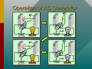
Chapter 31A -Chapter 31A -
Electromagnetic InductionElectromagnetic Induction
A PowerPoint Presentation byA PowerPoint Presentation by
Paul E. Tippens, Professor of PhysicsPaul E. Tippens, Professor of Physics
Southern Polytechnic State UniversitySouthern Polytechnic State University
© 2007
Objectives:Objectives: After completing thisAfter completing this
module, you should be able to:module, you should be able to:
• Calculate theCalculate the magnitudemagnitude andand directiondirection ofof
thethe induced current or emfinduced current or emf in a conductorin a conductor
moving with respect to a givenmoving with respect to a given B-fieldB-field..
• Calculate theCalculate the magnetic fluxmagnetic flux through anthrough an
area in a givenarea in a given B-fieldB-field..
• ApplyApply Lenz’s lawLenz’s law and theand the right-hand ruleright-hand rule
to determine directions of induced emf.to determine directions of induced emf.
• Describe the operation and use of ac andDescribe the operation and use of ac and
dcdc generatorsgenerators oror motorsmotors..
Induced CurrentInduced Current
When a conductor movesWhen a conductor moves
across flux lines, magneticacross flux lines, magnetic
forces on the free electronsforces on the free electrons
induceinduce an electric current.an electric current.
When a conductor movesWhen a conductor moves
across flux lines, magneticacross flux lines, magnetic
forces on the free electronsforces on the free electrons
induceinduce an electric current.an electric current.
Right-hand force ruleRight-hand force rule showsshows
current outward for down andcurrent outward for down and
inward for up motion. (Verify)inward for up motion. (Verify)
Right-hand force ruleRight-hand force rule showsshows
current outward for down andcurrent outward for down and
inward for up motion. (Verify)inward for up motion. (Verify)
Down II
Down
vv
B
FF
Up vv
B
FF
Up
II
B
Induced EMF: ObservationsInduced EMF: Observations
B Flux lines Φ in Wb
N turns; velocityv
Faraday’s Law:
Faraday’s observations:Faraday’s observations:
• Relative motion induces emf.Relative motion induces emf.
• Direction of emf depends onDirection of emf depends on
direction of motion.direction of motion.
• Emf is proportional to rate atEmf is proportional to rate at
which lines are cut (which lines are cut (v).v).
• EmfEmf is proportional to theis proportional to the
number of turnsnumber of turns NN..
-N
t
∆Φ
∆
E =
TheThe negativenegative sign means thatsign means that EE opposesopposes its cause.its cause.
Magnetic Flux DensityMagnetic Flux Density
∆φ
Magnetic Flux
density:
∆AB
A
Φ
=
• Magnetic flux linesMagnetic flux lines
ΦΦ are continuousare continuous
and closed.and closed.
• Direction is that ofDirection is that of
thethe BB vector atvector at
any point.any point.
; =B BA
A
Φ
= ΦWhen area A is
perpendicular to flux:
When area A is
perpendicular to flux:
The unit of flux density is theThe unit of flux density is the weber per square meterweber per square meter..
Calculating Flux When AreaCalculating Flux When Area
is Not Perpendicular to Fieldis Not Perpendicular to Field
The flux penetrating theThe flux penetrating the
areaarea AA when the normalwhen the normal
vectorvector nn makes an anglemakes an angle
ofof θθ with thewith the B-fieldB-field is:is:
cosBA θΦ =
The angleThe angle θθ is the complement of the angleis the complement of the angle αα that thethat the
plane of the area makes withplane of the area makes with BB field. (field. (CosCos θθ = Sin= Sin αα))
n
A θ
α
B
Example 1:Example 1: A current loop has an area ofA current loop has an area of 40 cm40 cm22
and is placed in aand is placed in a 3-T3-T B-field at the given angles.B-field at the given angles.
Find theFind the fluxflux ΦΦ through the loop in each case.through the loop in each case.
A
n
n
n
A = 40 cm2
(a) θ = 00 (c) θ = 600
(b) θ = 900
θ
x x x x
x x x x
x x x x
x x x x
(a)(a) ΦΦ == BABA cos 0cos 000
= (3 T)(0.004 m= (3 T)(0.004 m22
)(1);)(1); Φ =Φ = 12.0 mWb12.0 mWb
(b)(b) ΦΦ == BABA cos 90cos 9000
= (3 T)(0.004 m= (3 T)(0.004 m22
)(0);)(0); Φ =Φ = 0 mWb0 mWb
(c)(c) ΦΦ == BABA cos 60cos 6000
= (3 T)(0.004 m= (3 T)(0.004 m22
)(0.5);)(0.5); Φ =Φ = 6.00 mWb6.00 mWb
Application of Faraday’s LawApplication of Faraday’s Law
Faraday’s Law:
-N
t
∆Φ
∆
E =
A change in fluxA change in flux ∆Φ∆Φ cancan
occur by a change in areaoccur by a change in area
or by a change in the B-or by a change in the B-
field:field:
∆Φ∆Φ = B= B ∆∆AA ∆Φ∆Φ = A= A ∆∆BB
n
n
n
Rotating loop = B ∆A Loop at rest = A ∆B
Example 2:Example 2: A coil hasA coil has 200 turns200 turns of areaof area 30 cm30 cm22
..
It flips from vertical to horizontal position in aIt flips from vertical to horizontal position in a
time oftime of 0.03 s0.03 s. What is the induced emf if the. What is the induced emf if the
constant B-field isconstant B-field is 4 mT4 mT??
SN
nn
θθ
B
N = 200 turns
B = 4 mT; 00
to 900
∆∆A = 30 cmA = 30 cm22
– 0 = 30 cm– 0 = 30 cm22
∆Φ∆Φ = B= B ∆∆A = (3 mT)(30 cmA = (3 mT)(30 cm22
))
∆Φ∆Φ = (0.004 T)(0.0030 m= (0.004 T)(0.0030 m22
))
∆Φ∆Φ = 1.2 x 10= 1.2 x 10⁻⁵-5
WbWb
-5
1.2 x 10 Wb
(200)
0.03 s
N
t
∆Φ
= − = −
∆
E E = -0.080 VE = -0.080 V
The negative sign indicates the polarity of the voltage.The negative sign indicates the polarity of the voltage.
Lenz’s LawLenz’s Law
Lenz’s law:Lenz’s law: An induced current will be in such a directionAn induced current will be in such a direction
as to produce a magnetic field that willas to produce a magnetic field that will opposeoppose thethe
motion of the magnetic field that is producing it.motion of the magnetic field that is producing it.
Flux decreasing by right move
induces loop flux to the left.
N S
Left motion
II
Induced B
Flux increasing to left induces
loop flux to the right.
N S
Right motionII
Induced B
Example 3:Example 3: UseUse Lenz’s lawLenz’s law to determine directionto determine direction
of induced current throughof induced current through RR if switch is closedif switch is closed
for circuit below (for circuit below (BB increasingincreasing).).
R
Close switch. Then what is
direction of induced current?
The rising current in right circuit causes flux toThe rising current in right circuit causes flux to increaseincrease
to the leftto the left, inducing current in left circuit that must, inducing current in left circuit that must
produce a rightward fieldproduce a rightward field to oppose motionto oppose motion. Hence. Hence
currentcurrent II through resistorthrough resistor RR is to the right as shown.is to the right as shown.
x x x x x x x x xx x x x x x x x x
x x x x x xx x x x x x
Directions of
Forces and EMFs
Directions of
Forces and EMFs
v
L
vI
I
x
BB
I
vv
Induced
emf
An emf E is induced by
moving wire at velocity v
in constant B field. Note
direction of I.
An emf E is induced by
moving wire at velocity v
in constant B field. Note
direction of I.
From Lenz’s law, we seeFrom Lenz’s law, we see
that athat a reverse fieldreverse field (out) is(out) is
created. This field causescreated. This field causes
a leftward force on the wirea leftward force on the wire
that offersthat offers resistanceresistance to theto the
motion. Use right-handmotion. Use right-hand
force rule to show this.force rule to show this.
x x xx x x
x x xx x x
x x xx x x
x x xx x x
x x xx x x
x xx x
xx B
I
Lenz’s law
v
Motional EMF in a WireMotional EMF in a Wire
L v
I
I
x
x x x x x x x x
x x x x x x
x x x x x x x
x x x x x x x
x x x x x x x
x x x x x x x
x x x x
BB
F
vv
ForceForce FF on chargeon charge qq in wire:in wire:
F = qvB;F = qvB; Work = FL = qvBLWork = FL = qvBL
Work qvBL
q q
=E =
EMF:EMF: BLvE =
If wire of length L moves withIf wire of length L moves with
velocityvelocity vv an anglean angle θθ withwith B:B:
Induced Emf E
v sin θ
v
θ
B
sinBLv θE =
Example 4:Example 4: A 0.20-m length of wire moves atA 0.20-m length of wire moves at
a constant speed of 5 m/s in at 140a constant speed of 5 m/s in at 14000
with awith a
0.4-T0.4-T B-B-Field. What is the magnitude andField. What is the magnitude and
direction of the induced emf in the wire?direction of the induced emf in the wire?
v
θ
B
North
South
sinBLv θE =
0
(0.4 T)(0.20 m)(5 m/s)sin140E =
EE = -0.257 V= -0.257 V
UsingUsing right-hand ruleright-hand rule, point fingers, point fingers
to right, thumb along velocity, andto right, thumb along velocity, and
hand pushes in direction of inducedhand pushes in direction of induced
emf—to theemf—to the northnorth in the diagram.in the diagram.
UsingUsing right-hand ruleright-hand rule, point fingers, point fingers
to right, thumb along velocity, andto right, thumb along velocity, and
hand pushes in direction of inducedhand pushes in direction of induced
emf—to theemf—to the northnorth in the diagram.in the diagram.
v
B
North
South
I
The AC GeneratorThe AC Generator
Rotating Loop in B-field
• An alternatingAn alternating AC currentAC current isis
produced by rotating a loopproduced by rotating a loop
in a constantin a constant BB-field-field..
• Current onCurrent on leftleft isis outwardoutward byby
right-hand rule.right-hand rule.
• TheThe rightright segment has ansegment has an
inwardinward current.current.
• When loop isWhen loop is verticalvertical, the, the
current iscurrent is zerozero..
vv
B
II
vv
B
II
II inin RR is right, zero, left, and then zero as loop rotates.is right, zero, left, and then zero as loop rotates.
Operation of AC GeneratorOperation of AC Generator
I=0
I=0
Calculating Induced EMFCalculating Induced EMF
a
b
n
B
Area A = ab
xx
.. n
v
B
θ
θ
b/2
Each segmentEach segment aa
has constanthas constant
velocityvelocity vv..
RectangularRectangular
looploop a x ba x b
xx
n
v
B
θ
θ
r = b/2
v sin θ
v = ωrBothBoth segmentssegments aa moving withmoving with vv
at angleat angle θθ withwith BB gives emf:gives emf:
sin ;Bav θE = ( )2
bv rω ω= =
( )22 sinT
bBa ω θ=E
sinT
BAω θ=E
Sinusoidal Current ofSinusoidal Current of
GeneratorGenerator
The emf varies sinusoidally with max and min emf
+E
-E
sinNBAω θ=EForFor NN turns, the EMF is:turns, the EMF is:
xx
..
xx
..
Example 5:Example 5: An ac generator hasAn ac generator has 12 turns12 turns ofof
wire of areawire of area 0.08 m0.08 m22
. The loop rotates in a. The loop rotates in a
magnetic field ofmagnetic field of 0.3 T0.3 T at a frequency ofat a frequency of 6060
HzHz. Find the maximum induced emf.. Find the maximum induced emf.
xx
.. n
Bθ
f = 60 Hz
ωω = 2= 2ππf =f = 22ππ(60(60 Hz) = 377 rad/sHz) = 377 rad/s
max ; Since sin 1NBAω θ =E =
2
max (12)(0.3 T)(.08 m )(377 rad/s)E =
Emf is maximum whenEmf is maximum when θθ = 90= 9000
..
The maximum emf generated is therefore:The maximum emf generated is therefore: Emax = 109 V
If the resistance is known, thenIf the resistance is known, then Ohm’s lawOhm’s law ((V = IRV = IR)) cancan
be applied to find the maximum induced current.be applied to find the maximum induced current.
If the resistance is known, thenIf the resistance is known, then Ohm’s lawOhm’s law ((V = IRV = IR)) cancan
be applied to find the maximum induced current.be applied to find the maximum induced current.
The DC GeneratorThe DC Generator
DC Generator
The simple ac generatorThe simple ac generator
can be converted to acan be converted to a dcdc
generatorgenerator by using a singleby using a single
split-ring commutatorsplit-ring commutator toto
reverse connections twicereverse connections twice
per revolution.per revolution.
Commutator
For the dc generator: The emf fluctuates in magnitude,
but always has the same direction (polarity).
For the dc generator: The emf fluctuates in magnitude,
but always has the same direction (polarity).
tt
EE
The Electric MotorThe Electric Motor
In a simpleIn a simple electric motorelectric motor, a current loop experiences a, a current loop experiences a
torque which produces rotational motion. Such motiontorque which produces rotational motion. Such motion
induces ainduces a back emfback emf to oppose the motion.to oppose the motion.
In a simpleIn a simple electric motorelectric motor, a current loop experiences a, a current loop experiences a
torque which produces rotational motion. Such motiontorque which produces rotational motion. Such motion
induces ainduces a back emfback emf to oppose the motion.to oppose the motion.
Electric Motor
V
V – Eb = IRV – Eb = IR
Applied voltage – back emf =Applied voltage – back emf =
net voltagenet voltage
Since back emfSince back emf EEbb increases withincreases with
rotational frequencyrotational frequency, the starting, the starting
current is high and the operatingcurrent is high and the operating
current is low:current is low: EEbb = NBA= NBAωω sinsin θθ
Since back emfSince back emf EEbb increases withincreases with
rotational frequencyrotational frequency, the starting, the starting
current is high and the operatingcurrent is high and the operating
current is low:current is low: EEbb = NBA= NBAωω sinsin θθ
Eb
II
Armature and Field WindingsArmature and Field Windings
In the commercial motor,
many coils of wire around
the armature will produce
a smooth torque. (Note
directions of I in wires.)
Series-Wound Motor: The
field and armature wiring
are connected in series.
MotorMotor
Shunt-Wound Motor: The field windings and the
armature windings are connected in parallel.
Example 6:Example 6: A series-wound dc motor has anA series-wound dc motor has an
internal resistance ofinternal resistance of 33 ΩΩ. The. The 120-V120-V supplysupply
line drawsline draws 4 A4 A when at full speed. What is thewhen at full speed. What is the
emf in the motor and the starting current?emf in the motor and the starting current?
V
Eb
II
V – Eb = IRV – Eb = IRRecall that:Recall that:
120 V –120 V – EEbb = (4 A)(3= (4 A)(3 Ω)Ω)
Eb = 108 VThe back emfThe back emf
in motor:in motor:
The starting current IThe starting current Iss is found by noting thatis found by noting that EEbb = 0 in= 0 in
beginning (armature has not started rotating).beginning (armature has not started rotating).
120 V – 0 =120 V – 0 = IIss (3(3 Ω)Ω) Is = 40 A
SummarySummary
Faraday’s Law:
-N
t
∆Φ
∆
E =
A change in fluxA change in flux ∆Φ∆Φ cancan
occur by a change in areaoccur by a change in area
or by a change in the B-or by a change in the B-
field:field:
∆Φ∆Φ = B= B ∆∆AA ∆Φ∆Φ = A= A ∆∆BB
cosBA θΦ =; =B BA
A
Φ
= Φ
Calculating flux through an area in a B-field:Calculating flux through an area in a B-field:
Summary (Cont.)Summary (Cont.)
Lenz’s law:Lenz’s law: An induced current will be in such a directionAn induced current will be in such a direction
as to produce a magnetic field that willas to produce a magnetic field that will opposeoppose thethe
motion of the magnetic field that is producing it.motion of the magnetic field that is producing it.
Flux decreasing by right move
induces loop flux to the left.
N S
Left motion
II
Induced B
Flux increasing to left induces
loop flux to the right.
N S
Right motionII
Induced B
Summary (Cont.)Summary (Cont.)
sinBLv θE = Induced Emf E
v sin θ
v
θ
B
An emf is induced by a wire
moving with a velocity v at an
angle θ with a B-field.
sinNBAω θ=EForFor NN turns, the EMF is:turns, the EMF is:
In general for a coil of N turns of area A rotating
with a frequency in a B-field, the generated emf
is given by the following relationship:
In general for a coil of N turns of area A rotating
with a frequency in a B-field, the generated emf
is given by the following relationship:
Summary (Cont.)Summary (Cont.)
DC Generator Electric Motor
V
The ac generator isThe ac generator is
shown to the right. Theshown to the right. The
dc generator and a dcdc generator and a dc
motor are shown below:motor are shown below:
The ac generator isThe ac generator is
shown to the right. Theshown to the right. The
dc generator and a dcdc generator and a dc
motor are shown below:motor are shown below:
Summary (Cont.)Summary (Cont.)
V – Eb = IRV – Eb = IR
Applied voltage – back emf =Applied voltage – back emf =
net voltagenet voltage
The rotor generates a backThe rotor generates a back
emf in the operation of aemf in the operation of a
motor that reduces themotor that reduces the
applied voltage. Theapplied voltage. The
following relationship exists:following relationship exists:
The rotor generates a backThe rotor generates a back
emf in the operation of aemf in the operation of a
motor that reduces themotor that reduces the
applied voltage. Theapplied voltage. The
following relationship exists:following relationship exists:
MotorMotor
CONCLUSION: Chapter 31ACONCLUSION: Chapter 31A
Electromagnetic InductionElectromagnetic Induction

Electromagnetic induction

  • 1.
    Chapter 31A -Chapter31A - Electromagnetic InductionElectromagnetic Induction A PowerPoint Presentation byA PowerPoint Presentation by Paul E. Tippens, Professor of PhysicsPaul E. Tippens, Professor of Physics Southern Polytechnic State UniversitySouthern Polytechnic State University © 2007
  • 2.
    Objectives:Objectives: After completingthisAfter completing this module, you should be able to:module, you should be able to: • Calculate theCalculate the magnitudemagnitude andand directiondirection ofof thethe induced current or emfinduced current or emf in a conductorin a conductor moving with respect to a givenmoving with respect to a given B-fieldB-field.. • Calculate theCalculate the magnetic fluxmagnetic flux through anthrough an area in a givenarea in a given B-fieldB-field.. • ApplyApply Lenz’s lawLenz’s law and theand the right-hand ruleright-hand rule to determine directions of induced emf.to determine directions of induced emf. • Describe the operation and use of ac andDescribe the operation and use of ac and dcdc generatorsgenerators oror motorsmotors..
  • 3.
    Induced CurrentInduced Current Whena conductor movesWhen a conductor moves across flux lines, magneticacross flux lines, magnetic forces on the free electronsforces on the free electrons induceinduce an electric current.an electric current. When a conductor movesWhen a conductor moves across flux lines, magneticacross flux lines, magnetic forces on the free electronsforces on the free electrons induceinduce an electric current.an electric current. Right-hand force ruleRight-hand force rule showsshows current outward for down andcurrent outward for down and inward for up motion. (Verify)inward for up motion. (Verify) Right-hand force ruleRight-hand force rule showsshows current outward for down andcurrent outward for down and inward for up motion. (Verify)inward for up motion. (Verify) Down II Down vv B FF Up vv B FF Up II B
  • 4.
    Induced EMF: ObservationsInducedEMF: Observations B Flux lines Φ in Wb N turns; velocityv Faraday’s Law: Faraday’s observations:Faraday’s observations: • Relative motion induces emf.Relative motion induces emf. • Direction of emf depends onDirection of emf depends on direction of motion.direction of motion. • Emf is proportional to rate atEmf is proportional to rate at which lines are cut (which lines are cut (v).v). • EmfEmf is proportional to theis proportional to the number of turnsnumber of turns NN.. -N t ∆Φ ∆ E = TheThe negativenegative sign means thatsign means that EE opposesopposes its cause.its cause.
  • 5.
    Magnetic Flux DensityMagneticFlux Density ∆φ Magnetic Flux density: ∆AB A Φ = • Magnetic flux linesMagnetic flux lines ΦΦ are continuousare continuous and closed.and closed. • Direction is that ofDirection is that of thethe BB vector atvector at any point.any point. ; =B BA A Φ = ΦWhen area A is perpendicular to flux: When area A is perpendicular to flux: The unit of flux density is theThe unit of flux density is the weber per square meterweber per square meter..
  • 6.
    Calculating Flux WhenAreaCalculating Flux When Area is Not Perpendicular to Fieldis Not Perpendicular to Field The flux penetrating theThe flux penetrating the areaarea AA when the normalwhen the normal vectorvector nn makes an anglemakes an angle ofof θθ with thewith the B-fieldB-field is:is: cosBA θΦ = The angleThe angle θθ is the complement of the angleis the complement of the angle αα that thethat the plane of the area makes withplane of the area makes with BB field. (field. (CosCos θθ = Sin= Sin αα)) n A θ α B
  • 7.
    Example 1:Example 1:A current loop has an area ofA current loop has an area of 40 cm40 cm22 and is placed in aand is placed in a 3-T3-T B-field at the given angles.B-field at the given angles. Find theFind the fluxflux ΦΦ through the loop in each case.through the loop in each case. A n n n A = 40 cm2 (a) θ = 00 (c) θ = 600 (b) θ = 900 θ x x x x x x x x x x x x x x x x (a)(a) ΦΦ == BABA cos 0cos 000 = (3 T)(0.004 m= (3 T)(0.004 m22 )(1);)(1); Φ =Φ = 12.0 mWb12.0 mWb (b)(b) ΦΦ == BABA cos 90cos 9000 = (3 T)(0.004 m= (3 T)(0.004 m22 )(0);)(0); Φ =Φ = 0 mWb0 mWb (c)(c) ΦΦ == BABA cos 60cos 6000 = (3 T)(0.004 m= (3 T)(0.004 m22 )(0.5);)(0.5); Φ =Φ = 6.00 mWb6.00 mWb
  • 8.
    Application of Faraday’sLawApplication of Faraday’s Law Faraday’s Law: -N t ∆Φ ∆ E = A change in fluxA change in flux ∆Φ∆Φ cancan occur by a change in areaoccur by a change in area or by a change in the B-or by a change in the B- field:field: ∆Φ∆Φ = B= B ∆∆AA ∆Φ∆Φ = A= A ∆∆BB n n n Rotating loop = B ∆A Loop at rest = A ∆B
  • 9.
    Example 2:Example 2:A coil hasA coil has 200 turns200 turns of areaof area 30 cm30 cm22 .. It flips from vertical to horizontal position in aIt flips from vertical to horizontal position in a time oftime of 0.03 s0.03 s. What is the induced emf if the. What is the induced emf if the constant B-field isconstant B-field is 4 mT4 mT?? SN nn θθ B N = 200 turns B = 4 mT; 00 to 900 ∆∆A = 30 cmA = 30 cm22 – 0 = 30 cm– 0 = 30 cm22 ∆Φ∆Φ = B= B ∆∆A = (3 mT)(30 cmA = (3 mT)(30 cm22 )) ∆Φ∆Φ = (0.004 T)(0.0030 m= (0.004 T)(0.0030 m22 )) ∆Φ∆Φ = 1.2 x 10= 1.2 x 10⁻⁵-5 WbWb -5 1.2 x 10 Wb (200) 0.03 s N t ∆Φ = − = − ∆ E E = -0.080 VE = -0.080 V The negative sign indicates the polarity of the voltage.The negative sign indicates the polarity of the voltage.
  • 10.
    Lenz’s LawLenz’s Law Lenz’slaw:Lenz’s law: An induced current will be in such a directionAn induced current will be in such a direction as to produce a magnetic field that willas to produce a magnetic field that will opposeoppose thethe motion of the magnetic field that is producing it.motion of the magnetic field that is producing it. Lenz’s law:Lenz’s law: An induced current will be in such a directionAn induced current will be in such a direction as to produce a magnetic field that willas to produce a magnetic field that will opposeoppose thethe motion of the magnetic field that is producing it.motion of the magnetic field that is producing it. Flux decreasing by right move induces loop flux to the left. N S Left motion II Induced B Flux increasing to left induces loop flux to the right. N S Right motionII Induced B
  • 11.
    Example 3:Example 3:UseUse Lenz’s lawLenz’s law to determine directionto determine direction of induced current throughof induced current through RR if switch is closedif switch is closed for circuit below (for circuit below (BB increasingincreasing).). R Close switch. Then what is direction of induced current? The rising current in right circuit causes flux toThe rising current in right circuit causes flux to increaseincrease to the leftto the left, inducing current in left circuit that must, inducing current in left circuit that must produce a rightward fieldproduce a rightward field to oppose motionto oppose motion. Hence. Hence currentcurrent II through resistorthrough resistor RR is to the right as shown.is to the right as shown. The rising current in right circuit causes flux toThe rising current in right circuit causes flux to increaseincrease to the leftto the left, inducing current in left circuit that must, inducing current in left circuit that must produce a rightward fieldproduce a rightward field to oppose motionto oppose motion. Hence. Hence currentcurrent II through resistorthrough resistor RR is to the right as shown.is to the right as shown.
  • 12.
    x x xx x x x x xx x x x x x x x x x x x x x x x x xx x x x x x x x x x x x x x x x x xx x x x x x x x x x x x x x x x x xx x x x x x x x x x x x x x x x x xx x x x x x x x x x x x x x x x x xx x x x x x x x x x x x x x xx x x x x x Directions of Forces and EMFs Directions of Forces and EMFs v L vI I x BB I vv Induced emf An emf E is induced by moving wire at velocity v in constant B field. Note direction of I. An emf E is induced by moving wire at velocity v in constant B field. Note direction of I. From Lenz’s law, we seeFrom Lenz’s law, we see that athat a reverse fieldreverse field (out) is(out) is created. This field causescreated. This field causes a leftward force on the wirea leftward force on the wire that offersthat offers resistanceresistance to theto the motion. Use right-handmotion. Use right-hand force rule to show this.force rule to show this. From Lenz’s law, we seeFrom Lenz’s law, we see that athat a reverse fieldreverse field (out) is(out) is created. This field causescreated. This field causes a leftward force on the wirea leftward force on the wire that offersthat offers resistanceresistance to theto the motion. Use right-handmotion. Use right-hand force rule to show this.force rule to show this. x x xx x x x x xx x x x x xx x x x x xx x x x x xx x x x xx x xx B I Lenz’s law v
  • 13.
    Motional EMF ina WireMotional EMF in a Wire L v I I x x x x x x x x x x x x x x x x x x x x x x x x x x x x x x x x x x x x x x x x x x x x x x x BB F vv ForceForce FF on chargeon charge qq in wire:in wire: F = qvB;F = qvB; Work = FL = qvBLWork = FL = qvBL Work qvBL q q =E = EMF:EMF: BLvE = If wire of length L moves withIf wire of length L moves with velocityvelocity vv an anglean angle θθ withwith B:B: Induced Emf E v sin θ v θ B sinBLv θE =
  • 14.
    Example 4:Example 4:A 0.20-m length of wire moves atA 0.20-m length of wire moves at a constant speed of 5 m/s in at 140a constant speed of 5 m/s in at 14000 with awith a 0.4-T0.4-T B-B-Field. What is the magnitude andField. What is the magnitude and direction of the induced emf in the wire?direction of the induced emf in the wire? v θ B North South sinBLv θE = 0 (0.4 T)(0.20 m)(5 m/s)sin140E = EE = -0.257 V= -0.257 V UsingUsing right-hand ruleright-hand rule, point fingers, point fingers to right, thumb along velocity, andto right, thumb along velocity, and hand pushes in direction of inducedhand pushes in direction of induced emf—to theemf—to the northnorth in the diagram.in the diagram. UsingUsing right-hand ruleright-hand rule, point fingers, point fingers to right, thumb along velocity, andto right, thumb along velocity, and hand pushes in direction of inducedhand pushes in direction of induced emf—to theemf—to the northnorth in the diagram.in the diagram. v B North South I
  • 15.
    The AC GeneratorTheAC Generator Rotating Loop in B-field • An alternatingAn alternating AC currentAC current isis produced by rotating a loopproduced by rotating a loop in a constantin a constant BB-field-field.. • Current onCurrent on leftleft isis outwardoutward byby right-hand rule.right-hand rule. • TheThe rightright segment has ansegment has an inwardinward current.current. • When loop isWhen loop is verticalvertical, the, the current iscurrent is zerozero.. vv B II vv B II II inin RR is right, zero, left, and then zero as loop rotates.is right, zero, left, and then zero as loop rotates.
  • 16.
    Operation of ACGeneratorOperation of AC Generator I=0 I=0
  • 17.
    Calculating Induced EMFCalculatingInduced EMF a b n B Area A = ab xx .. n v B θ θ b/2 Each segmentEach segment aa has constanthas constant velocityvelocity vv.. RectangularRectangular looploop a x ba x b xx n v B θ θ r = b/2 v sin θ v = ωrBothBoth segmentssegments aa moving withmoving with vv at angleat angle θθ withwith BB gives emf:gives emf: sin ;Bav θE = ( )2 bv rω ω= = ( )22 sinT bBa ω θ=E sinT BAω θ=E
  • 18.
    Sinusoidal Current ofSinusoidalCurrent of GeneratorGenerator The emf varies sinusoidally with max and min emf +E -E sinNBAω θ=EForFor NN turns, the EMF is:turns, the EMF is: xx .. xx ..
  • 19.
    Example 5:Example 5:An ac generator hasAn ac generator has 12 turns12 turns ofof wire of areawire of area 0.08 m0.08 m22 . The loop rotates in a. The loop rotates in a magnetic field ofmagnetic field of 0.3 T0.3 T at a frequency ofat a frequency of 6060 HzHz. Find the maximum induced emf.. Find the maximum induced emf. xx .. n Bθ f = 60 Hz ωω = 2= 2ππf =f = 22ππ(60(60 Hz) = 377 rad/sHz) = 377 rad/s max ; Since sin 1NBAω θ =E = 2 max (12)(0.3 T)(.08 m )(377 rad/s)E = Emf is maximum whenEmf is maximum when θθ = 90= 9000 .. The maximum emf generated is therefore:The maximum emf generated is therefore: Emax = 109 V If the resistance is known, thenIf the resistance is known, then Ohm’s lawOhm’s law ((V = IRV = IR)) cancan be applied to find the maximum induced current.be applied to find the maximum induced current. If the resistance is known, thenIf the resistance is known, then Ohm’s lawOhm’s law ((V = IRV = IR)) cancan be applied to find the maximum induced current.be applied to find the maximum induced current.
  • 20.
    The DC GeneratorTheDC Generator DC Generator The simple ac generatorThe simple ac generator can be converted to acan be converted to a dcdc generatorgenerator by using a singleby using a single split-ring commutatorsplit-ring commutator toto reverse connections twicereverse connections twice per revolution.per revolution. Commutator For the dc generator: The emf fluctuates in magnitude, but always has the same direction (polarity). For the dc generator: The emf fluctuates in magnitude, but always has the same direction (polarity). tt EE
  • 21.
    The Electric MotorTheElectric Motor In a simpleIn a simple electric motorelectric motor, a current loop experiences a, a current loop experiences a torque which produces rotational motion. Such motiontorque which produces rotational motion. Such motion induces ainduces a back emfback emf to oppose the motion.to oppose the motion. In a simpleIn a simple electric motorelectric motor, a current loop experiences a, a current loop experiences a torque which produces rotational motion. Such motiontorque which produces rotational motion. Such motion induces ainduces a back emfback emf to oppose the motion.to oppose the motion. Electric Motor V V – Eb = IRV – Eb = IR Applied voltage – back emf =Applied voltage – back emf = net voltagenet voltage Since back emfSince back emf EEbb increases withincreases with rotational frequencyrotational frequency, the starting, the starting current is high and the operatingcurrent is high and the operating current is low:current is low: EEbb = NBA= NBAωω sinsin θθ Since back emfSince back emf EEbb increases withincreases with rotational frequencyrotational frequency, the starting, the starting current is high and the operatingcurrent is high and the operating current is low:current is low: EEbb = NBA= NBAωω sinsin θθ Eb II
  • 22.
    Armature and FieldWindingsArmature and Field Windings In the commercial motor, many coils of wire around the armature will produce a smooth torque. (Note directions of I in wires.) Series-Wound Motor: The field and armature wiring are connected in series. MotorMotor Shunt-Wound Motor: The field windings and the armature windings are connected in parallel.
  • 23.
    Example 6:Example 6:A series-wound dc motor has anA series-wound dc motor has an internal resistance ofinternal resistance of 33 ΩΩ. The. The 120-V120-V supplysupply line drawsline draws 4 A4 A when at full speed. What is thewhen at full speed. What is the emf in the motor and the starting current?emf in the motor and the starting current? V Eb II V – Eb = IRV – Eb = IRRecall that:Recall that: 120 V –120 V – EEbb = (4 A)(3= (4 A)(3 Ω)Ω) Eb = 108 VThe back emfThe back emf in motor:in motor: The starting current IThe starting current Iss is found by noting thatis found by noting that EEbb = 0 in= 0 in beginning (armature has not started rotating).beginning (armature has not started rotating). 120 V – 0 =120 V – 0 = IIss (3(3 Ω)Ω) Is = 40 A
  • 24.
    SummarySummary Faraday’s Law: -N t ∆Φ ∆ E = Achange in fluxA change in flux ∆Φ∆Φ cancan occur by a change in areaoccur by a change in area or by a change in the B-or by a change in the B- field:field: ∆Φ∆Φ = B= B ∆∆AA ∆Φ∆Φ = A= A ∆∆BB cosBA θΦ =; =B BA A Φ = Φ Calculating flux through an area in a B-field:Calculating flux through an area in a B-field:
  • 25.
    Summary (Cont.)Summary (Cont.) Lenz’slaw:Lenz’s law: An induced current will be in such a directionAn induced current will be in such a direction as to produce a magnetic field that willas to produce a magnetic field that will opposeoppose thethe motion of the magnetic field that is producing it.motion of the magnetic field that is producing it. Lenz’s law:Lenz’s law: An induced current will be in such a directionAn induced current will be in such a direction as to produce a magnetic field that willas to produce a magnetic field that will opposeoppose thethe motion of the magnetic field that is producing it.motion of the magnetic field that is producing it. Flux decreasing by right move induces loop flux to the left. N S Left motion II Induced B Flux increasing to left induces loop flux to the right. N S Right motionII Induced B
  • 26.
    Summary (Cont.)Summary (Cont.) sinBLvθE = Induced Emf E v sin θ v θ B An emf is induced by a wire moving with a velocity v at an angle θ with a B-field. sinNBAω θ=EForFor NN turns, the EMF is:turns, the EMF is: In general for a coil of N turns of area A rotating with a frequency in a B-field, the generated emf is given by the following relationship: In general for a coil of N turns of area A rotating with a frequency in a B-field, the generated emf is given by the following relationship:
  • 27.
    Summary (Cont.)Summary (Cont.) DCGenerator Electric Motor V The ac generator isThe ac generator is shown to the right. Theshown to the right. The dc generator and a dcdc generator and a dc motor are shown below:motor are shown below: The ac generator isThe ac generator is shown to the right. Theshown to the right. The dc generator and a dcdc generator and a dc motor are shown below:motor are shown below:
  • 28.
    Summary (Cont.)Summary (Cont.) V– Eb = IRV – Eb = IR Applied voltage – back emf =Applied voltage – back emf = net voltagenet voltage The rotor generates a backThe rotor generates a back emf in the operation of aemf in the operation of a motor that reduces themotor that reduces the applied voltage. Theapplied voltage. The following relationship exists:following relationship exists: The rotor generates a backThe rotor generates a back emf in the operation of aemf in the operation of a motor that reduces themotor that reduces the applied voltage. Theapplied voltage. The following relationship exists:following relationship exists: MotorMotor
  • 29.
    CONCLUSION: Chapter 31ACONCLUSION:Chapter 31A Electromagnetic InductionElectromagnetic Induction