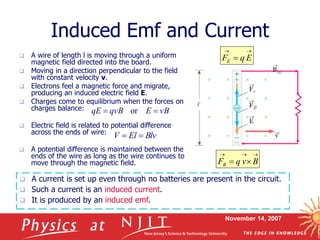
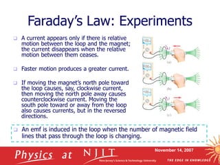
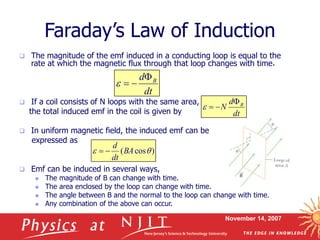
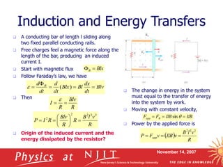
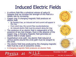
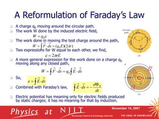
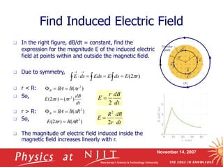
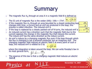
1. The document discusses Faraday's law of induction and induced electric fields. It summarizes that changing magnetic flux induces an electromotive force (emf) in a conductor.
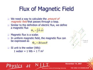
2. Faraday's law states that the magnitude of induced emf is equal to the rate of change of magnetic flux through a conductor. A changing magnetic field also induces an electric field in space.
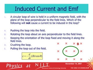
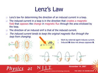
3. The document provides equations for calculating induced emf and electric fields. It also discusses Lenz's law, which describes the direction of induced current to oppose the change in magnetic flux that causes it.


![[L2 Sambhav] Electro magnetic induction.pdf](https://cdn.slidesharecdn.com/ss_thumbnails/l2sambhavemi-231215223335-2720969b-thumbnail.jpg?width=640&height=640&fit=bounds)


![Polymer [ बहुलक ] Chemistry Notes PDF - Irfanullah Mehar - JJ Sir Chemistry.pdf](https://cdn.slidesharecdn.com/ss_thumbnails/polymerchemistrynotespdf-irfanullahmehar-jjsirchemistry-260210172118-3f9b37f7-thumbnail.jpg?width=640&height=640&fit=bounds)


