Electro Magnetic Induction.ppt basic idea about EMI
1.
Lecture: YPH2001 :Physics
By Dr. Pranabi Maji
Assistant Professor
Department of Physics
Contact I’d: pranabi.maji@jisuniversity.ac.in, pranabi.ism@gmail.com
1
Date: 12/04/2024
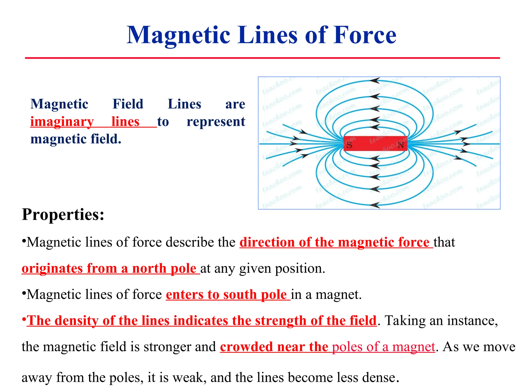
Magnetic Lines ofForce
Magnetic Field Lines are
imaginary lines to represent
magnetic field.
Properties:
•Magnetic lines of force describe the direction of the magnetic force that
originates from a north pole at any given position.
•Magnetic lines of force enters to south pole in a magnet.
•The density of the lines indicates the strength of the field. Taking an instance,
the magnetic field is stronger and crowded near the poles of a magnet. As we move
away from the poles, it is weak, and the lines become less dense.
4.
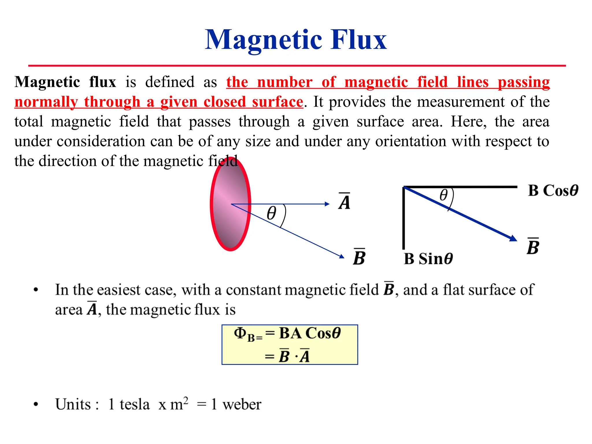
Magnetic Flux
Magnetic fluxis defined as the number of magnetic field lines passing
normally through a given closed surface. It provides the measurement of the
total magnetic field that passes through a given surface area. Here, the area
under consideration can be of any size and under any orientation with respect to
the direction of the magnetic field
5.
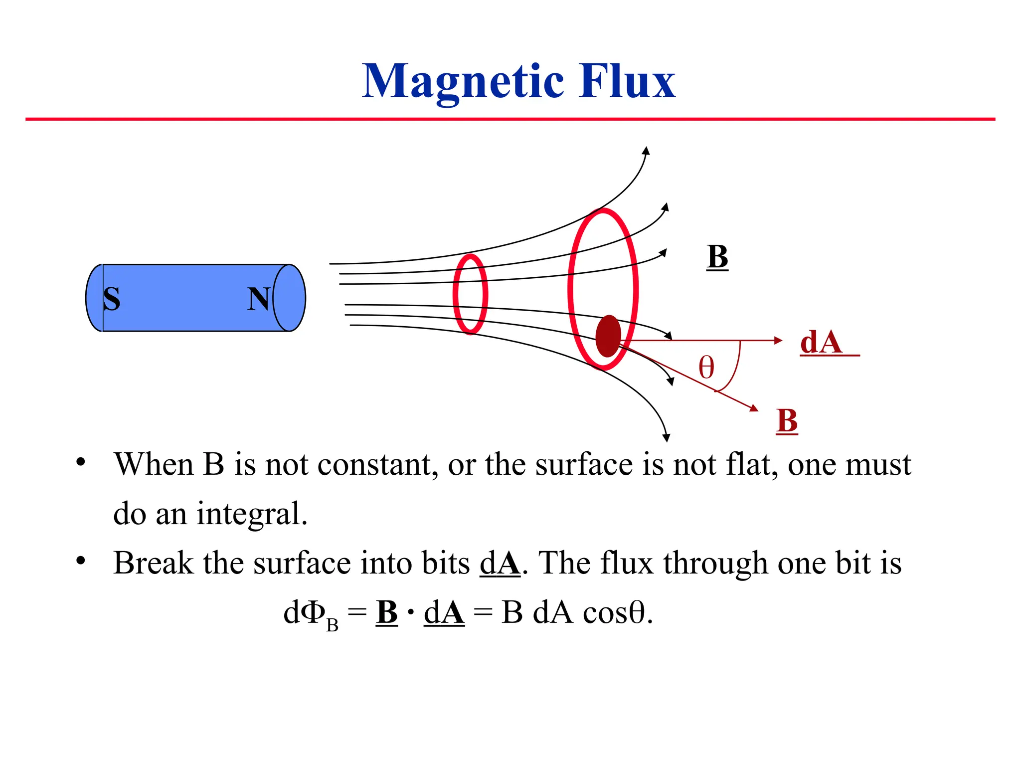
Magnetic Flux
• WhenB is not constant, or the surface is not flat, one must
do an integral.
• Break the surface into bits dA. The flux through one bit is
dB = B · dA = B dA cos
B
N
S
dA
B
.
6.
Magnetic Flux
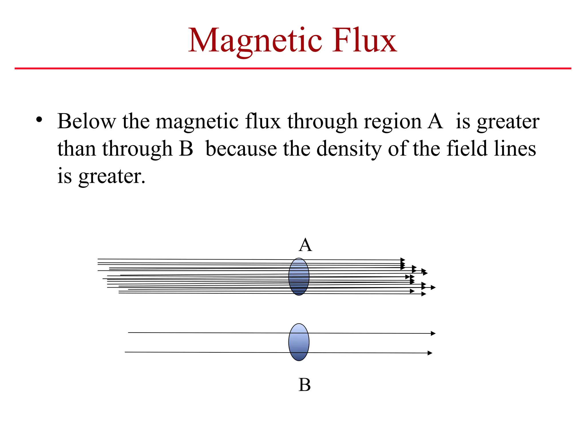
• Belowthe magnetic flux through region A is greater
than through B because the density of the field lines
is greater.
A
B
7.
Electromagnetic Induction
A changingmagnetic field
will induce an electromotive force (emf). This
Phenomena is called Electromagnetic Induction
In a closed electric circuit,
a changing magnetic field
will produce an electric current
8.
Faraday’s Experiments
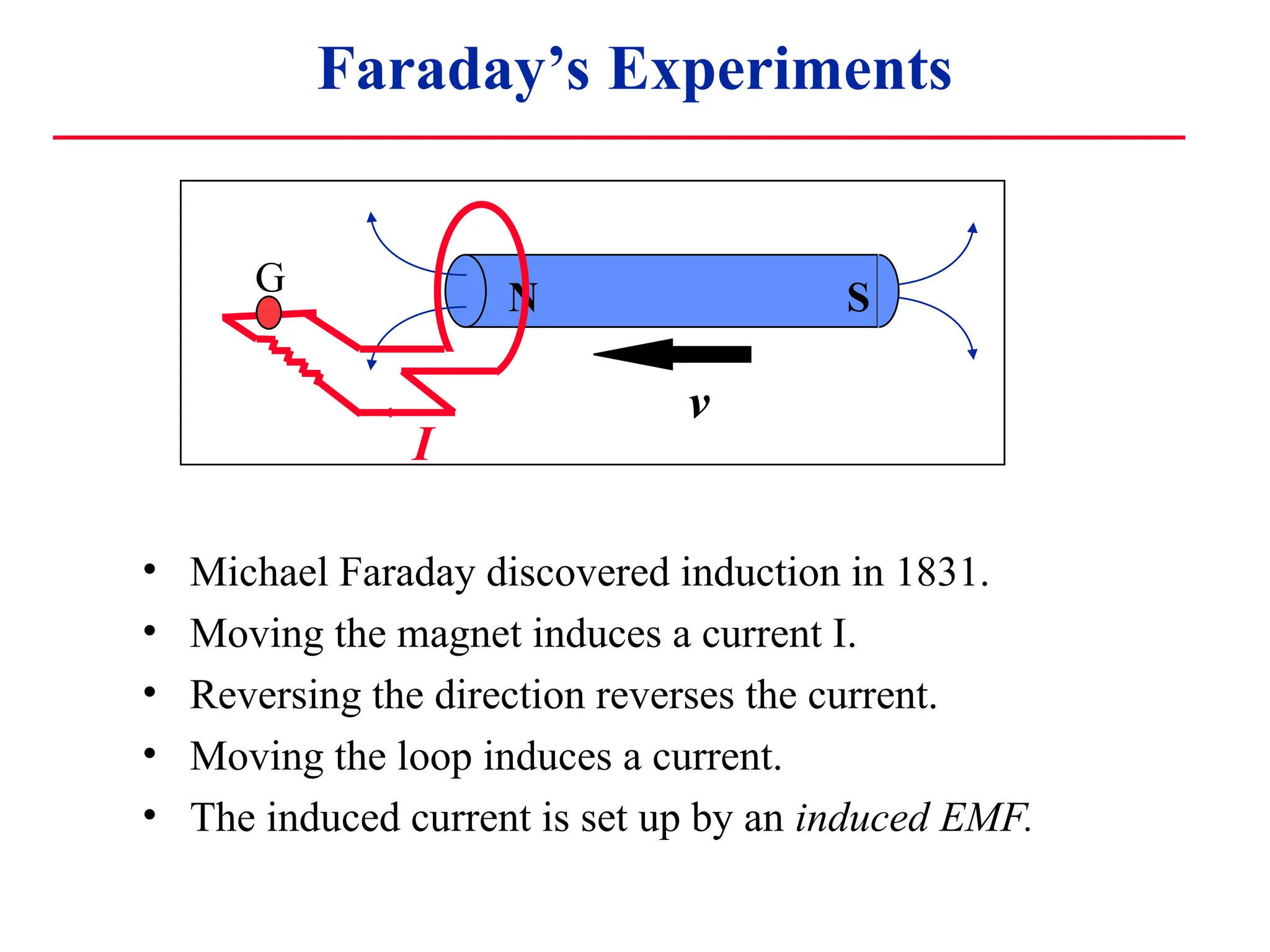
• MichaelFaraday discovered induction in 1831.
• Moving the magnet induces a current I.
• Reversing the direction reverses the current.
• Moving the loop induces a current.
• The induced current is set up by an induced EMF.
N S
I
v
G
9.
Faraday’s Experiments
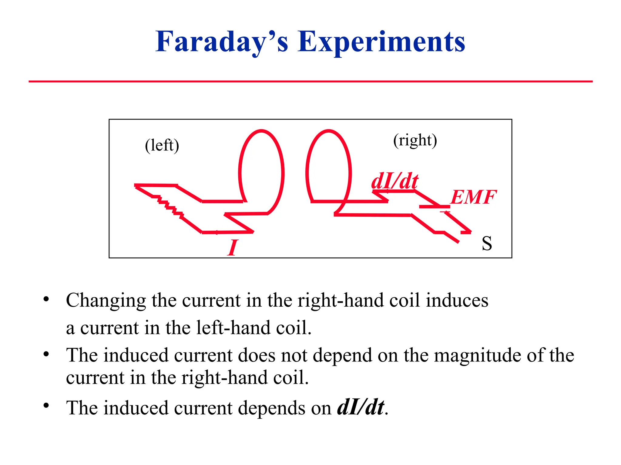
• Changingthe current in the right-hand coil induces
a current in the left-hand coil.
• The induced current does not depend on the magnitude of the
current in the right-hand coil.
• The induced current depends on dI/dt.
I
dI/dt
S
EMF
(right)
(left)
10.
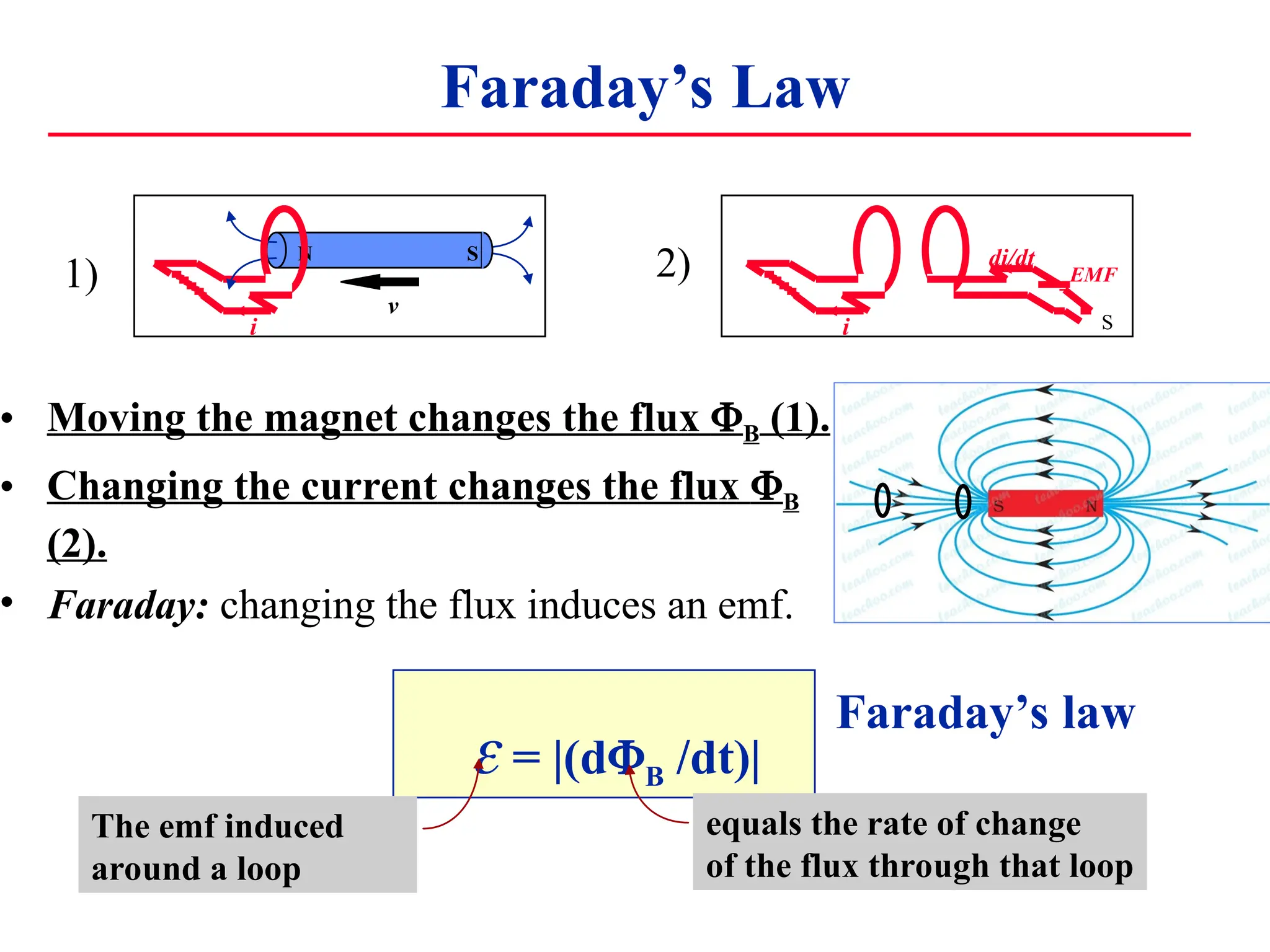
Faraday’s Law
• Movingthe magnet changes the flux B (1).
• Changing the current changes the flux B
(2).
• Faraday: changing the flux induces an emf.
i
di/dt
S
EMF
N S
i
v
= |(dB /dt)|
The emf induced
around a loop
equals the rate of change
of the flux through that loop
Faraday’s law
1) 2)
11.
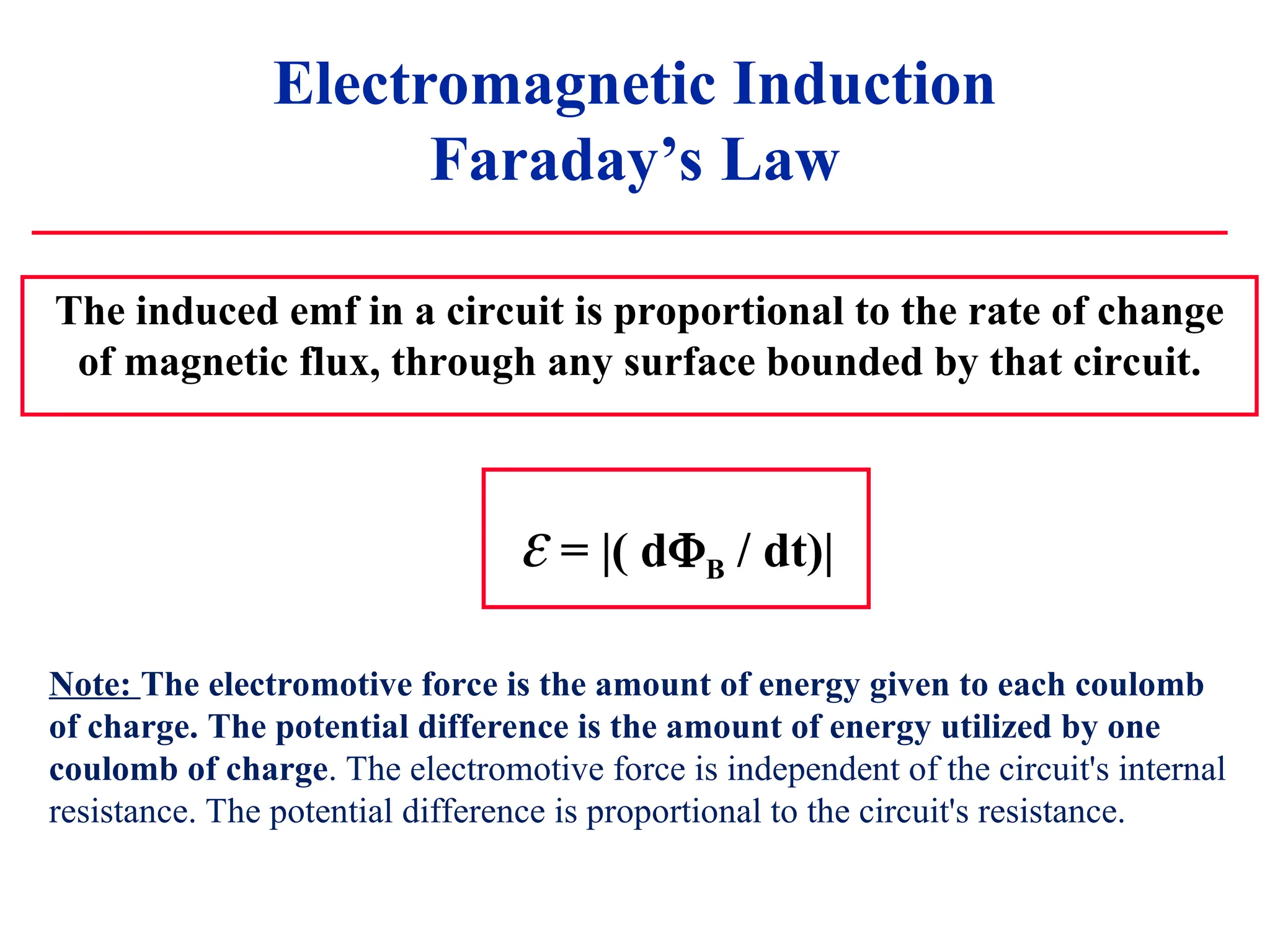
Electromagnetic Induction
Faraday’s Law
Theinduced emf in a circuit is proportional to the rate of change
of magnetic flux, through any surface bounded by that circuit.
= |( dB / dt)|
Note: The electromotive force is the amount of energy given to each coulomb
of charge. The potential difference is the amount of energy utilized by one
coulomb of charge. The electromotive force is independent of the circuit's internal
resistance. The potential difference is proportional to the circuit's resistance.
12.
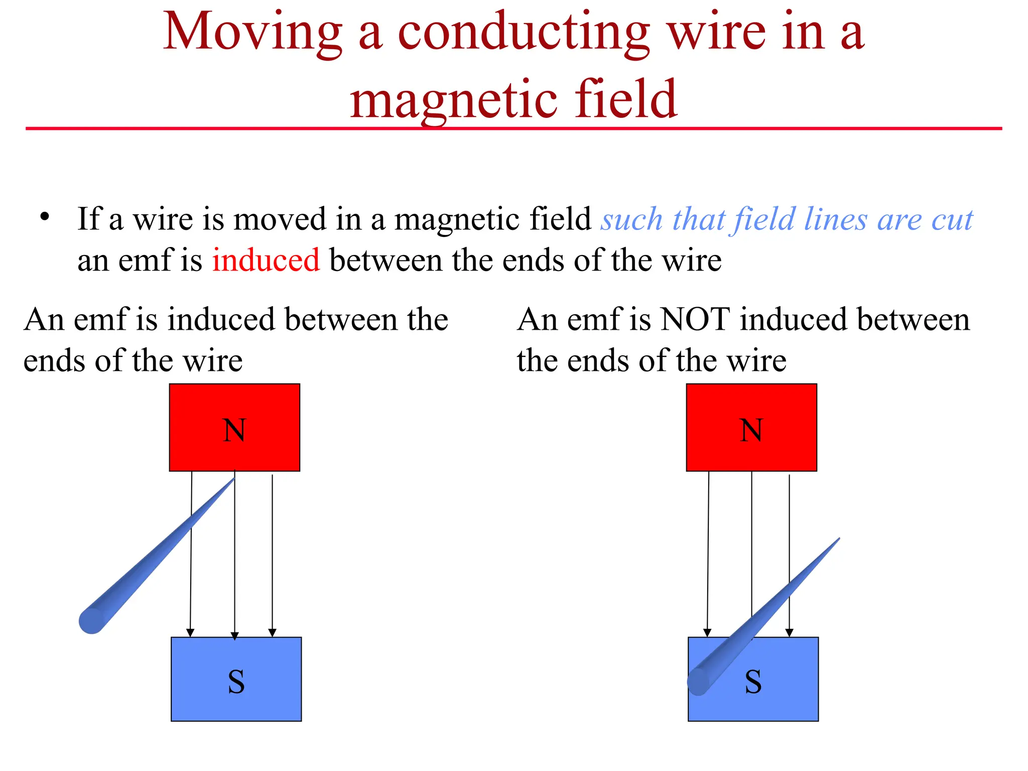
Moving a conductingwire in a
magnetic field
• If a wire is moved in a magnetic field such that field lines are cut
an emf is induced between the ends of the wire
N
S S
N
An emf is induced between the
ends of the wire
An emf is NOT induced between
the ends of the wire
13.
Lenz’s Law
• Lenz’sLaw:
The direction of induced emf is such that it always oppose the
phenomena of its generation (which causes the induced emf).
• This is easier to use than to say ...
Decreasing magnetic flux emf creates additional magnetic field
Increasing flux emf creates opposed magnetic field
14.
N
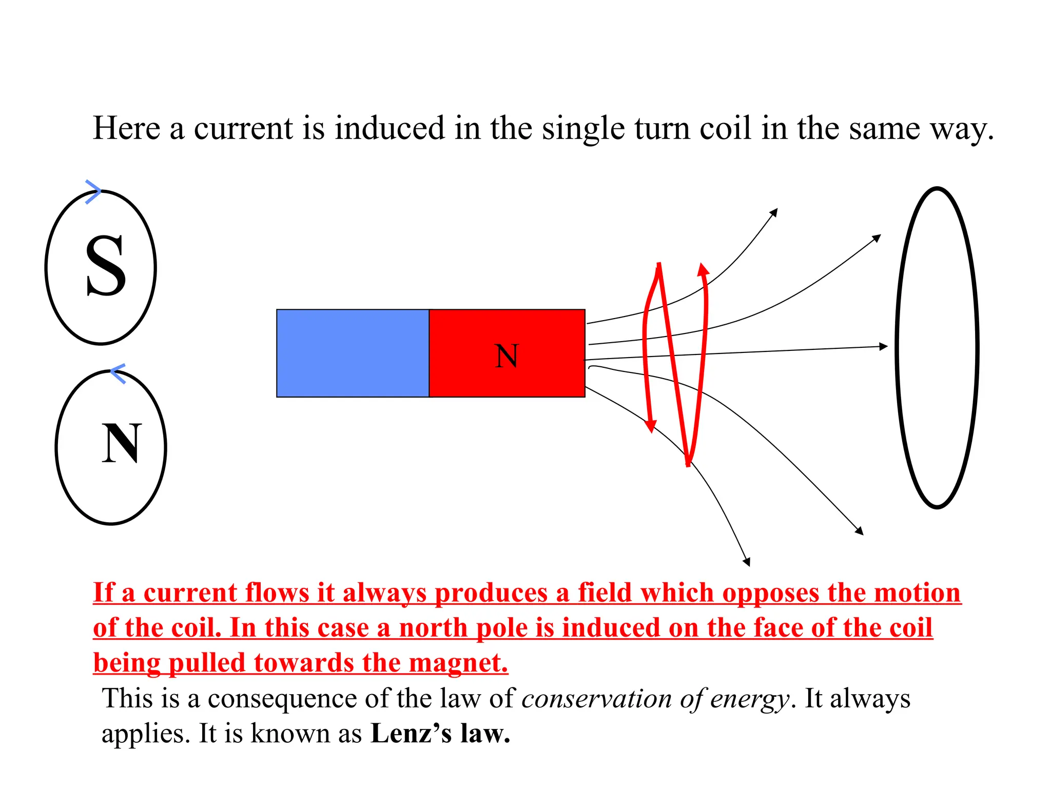
Here a currentis induced in the single turn coil in the same way.
If a current flows it always produces a field which opposes the motion
of the coil. In this case a north pole is induced on the face of the coil
being pulled towards the magnet.
This is a consequence of the law of conservation of energy. It always
applies. It is known as Lenz’s law.
S
N
15.
N
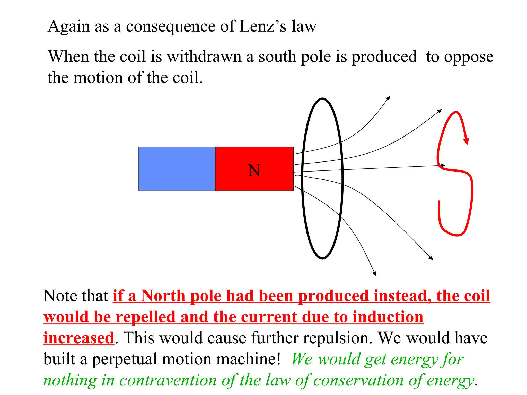
Again as aconsequence of Lenz’s law
When the coil is withdrawn a south pole is produced to oppose
the motion of the coil.
Note that if a North pole had been produced instead, the coil
would be repelled and the current due to induction
increased. This would cause further repulsion. We would have
built a perpetual motion machine! We would get energy for
nothing in contravention of the law of conservation of energy.
N
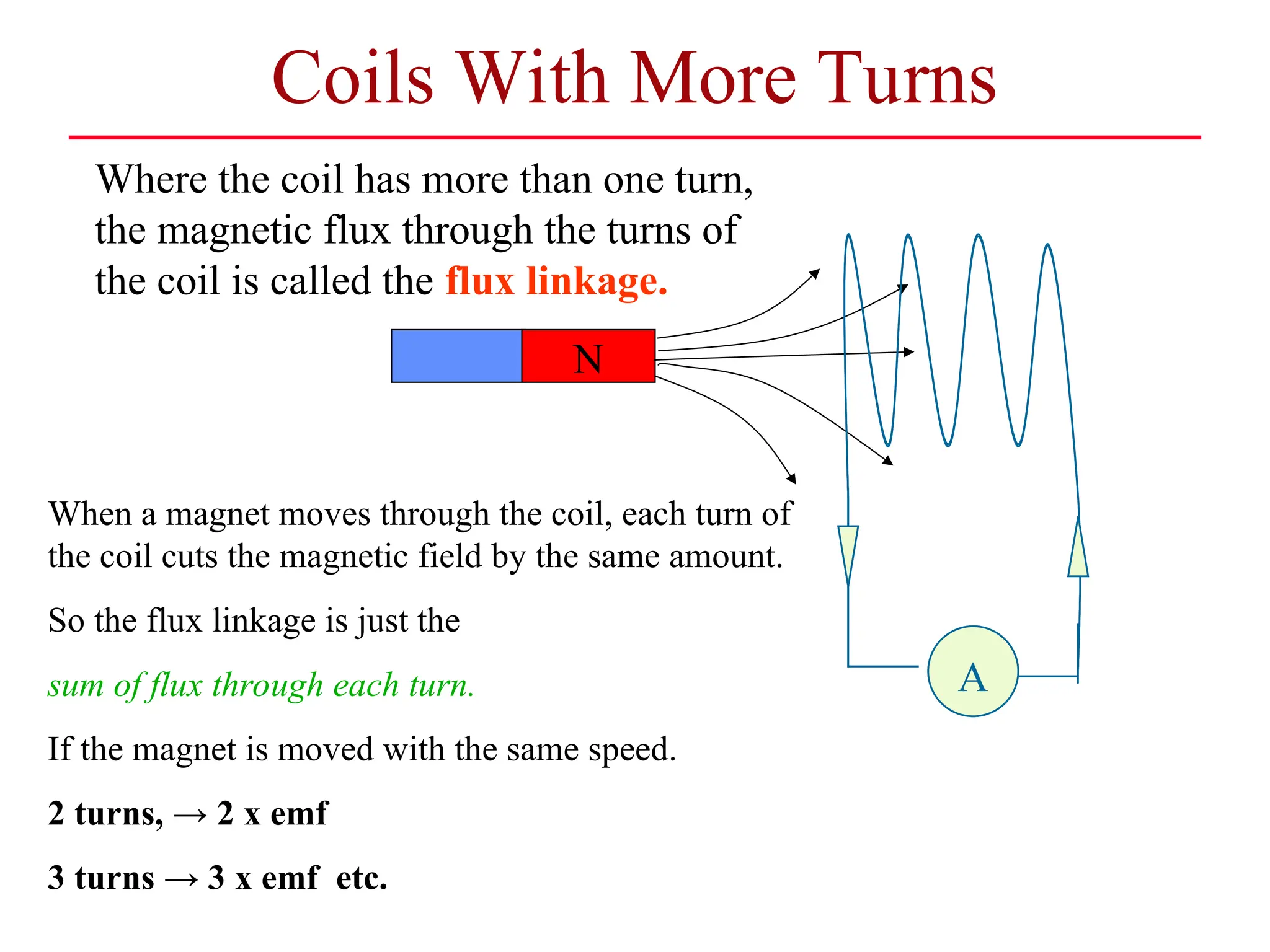
Coils With MoreTurns
A
A
A
When a magnet moves through the coil, each turn of
the coil cuts the magnetic field by the same amount.
So the flux linkage is just the
sum of flux through each turn.
If the magnet is moved with the same speed.
2 turns, → 2 x emf
3 turns → 3 x emf etc.
Where the coil has more than one turn,
the magnetic flux through the turns of
the coil is called the flux linkage.
18.
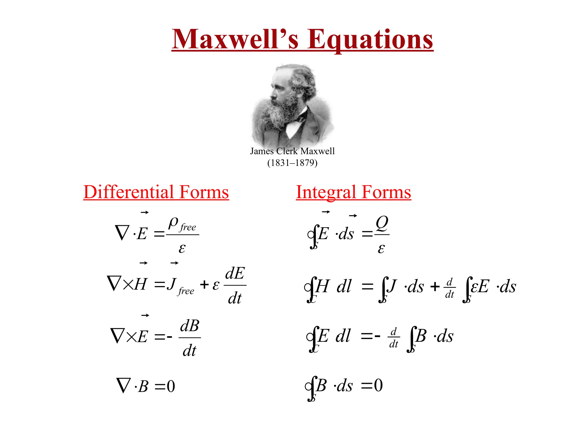
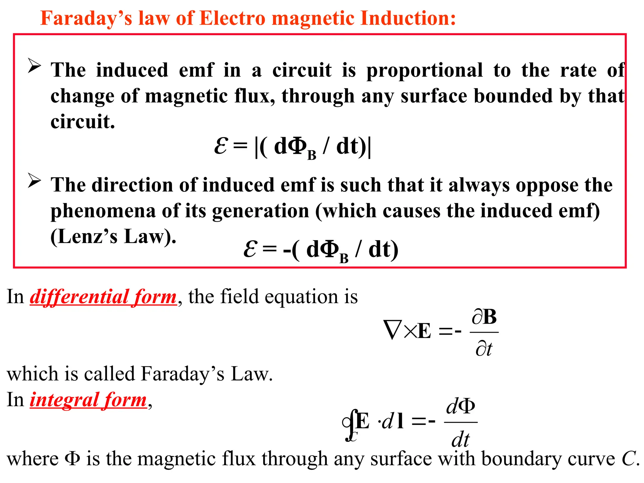
In differential form,the field equation is
which is called Faraday’s Law.
In integral form,
where is the magnetic flux through any surface with boundary curve C.
t
B
E
dt
d
d
C
l
E
The induced emf in a circuit is proportional to the rate of
change of magnetic flux, through any surface bounded by that
circuit.
The direction of induced emf is such that it always oppose the
phenomena of its generation (which causes the induced emf)
(Lenz’s Law).
Faraday’s law of Electro magnetic Induction:
= |( dB / dt)|
= -( dB / dt)
19.
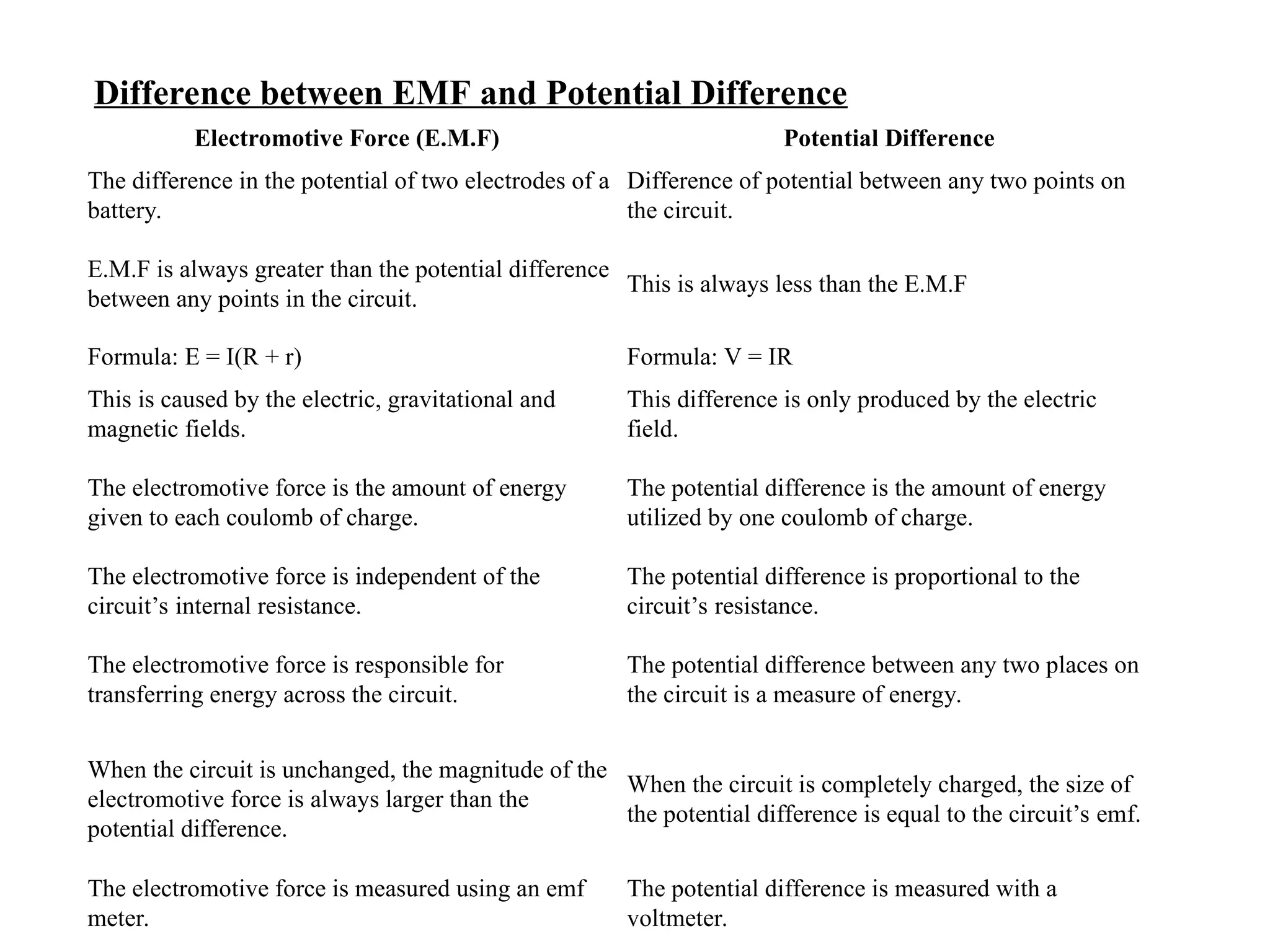
Electromotive Force (E.M.F)Potential Difference
The difference in the potential of two electrodes of a
battery.
Difference of potential between any two points on
the circuit.
E.M.F is always greater than the potential difference
between any points in the circuit.
This is always less than the E.M.F
Formula: E = I(R + r) Formula: V = IR
This is caused by the electric, gravitational and
magnetic fields.
This difference is only produced by the electric
field.
The electromotive force is the amount of energy
given to each coulomb of charge.
The potential difference is the amount of energy
utilized by one coulomb of charge.
The electromotive force is independent of the
circuit’s internal resistance.
The potential difference is proportional to the
circuit’s resistance.
The electromotive force is responsible for
transferring energy across the circuit.
The potential difference between any two places on
the circuit is a measure of energy.
When the circuit is unchanged, the magnitude of the
electromotive force is always larger than the
potential difference.
When the circuit is completely charged, the size of
the potential difference is equal to the circuit’s emf.
The electromotive force is measured using an emf
meter.
The potential difference is measured with a
voltmeter.
Difference between EMF and Potential Difference
20.
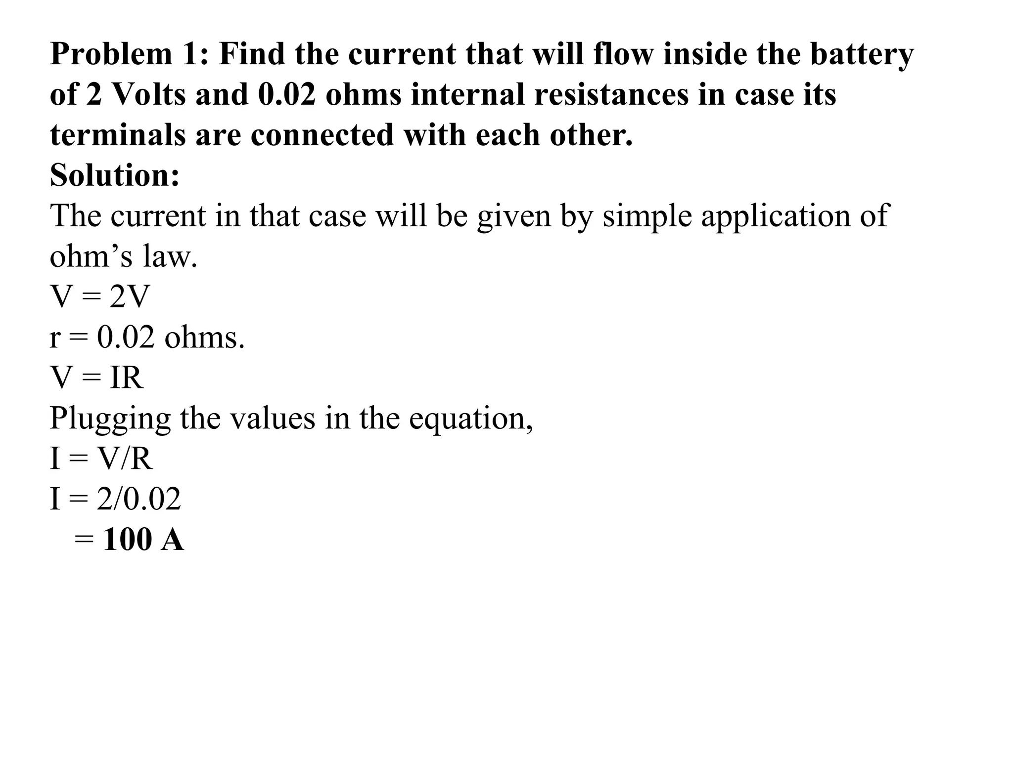
Problem 1: Findthe current that will flow inside the battery
of 2 Volts and 0.02 ohms internal resistances in case its
terminals are connected with each other.
Solution:
The current in that case will be given by simple application of
ohm’s law.
V = 2V
r = 0.02 ohms.
V = IR
Plugging the values in the equation,
I = V/R
I = 2/0.02
= 100 A
21.
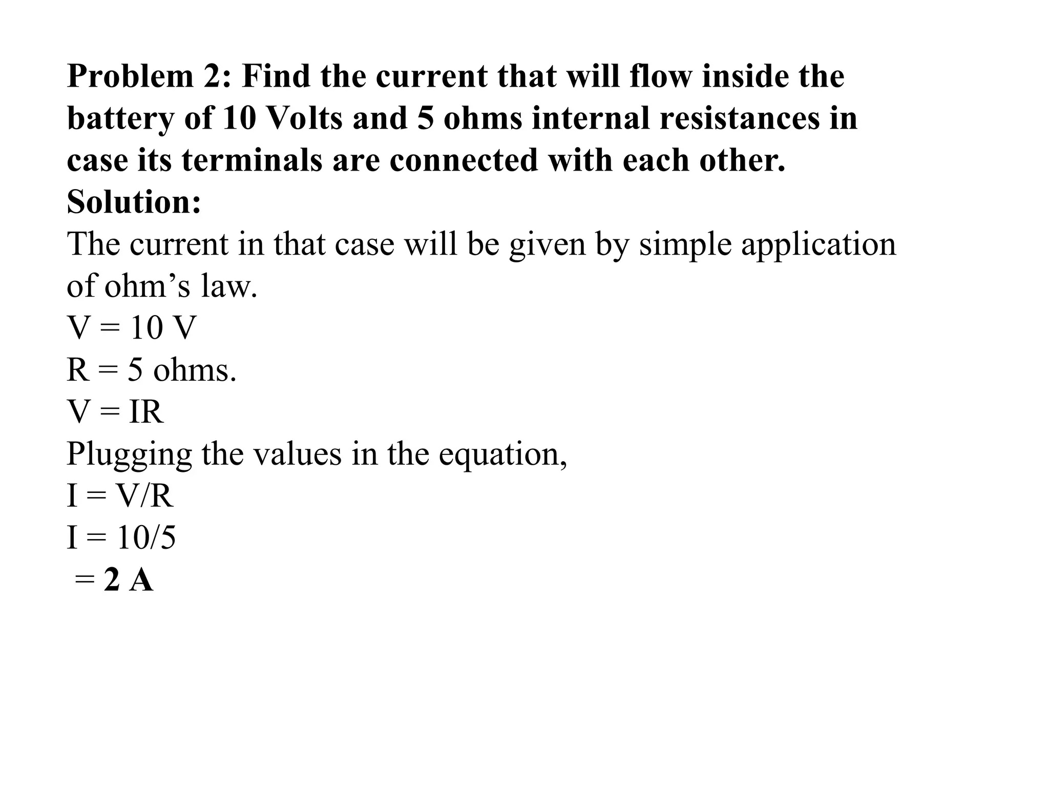
Problem 2: Findthe current that will flow inside the
battery of 10 Volts and 5 ohms internal resistances in
case its terminals are connected with each other.
Solution:
The current in that case will be given by simple application
of ohm’s law.
V = 10 V
R = 5 ohms.
V = IR
Plugging the values in the equation,
I = V/R
I = 10/5
= 2 A
22.
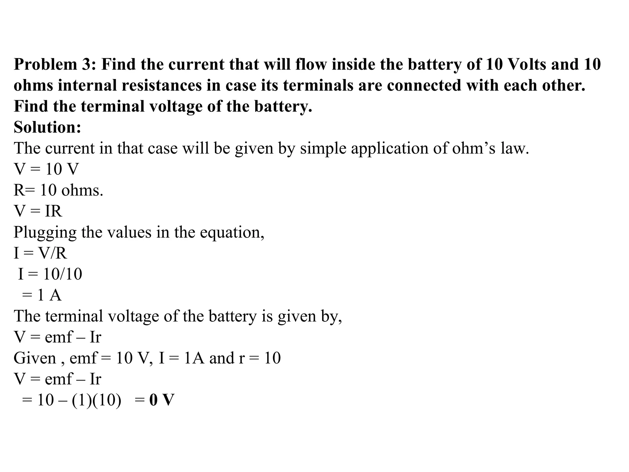
Problem 3: Findthe current that will flow inside the battery of 10 Volts and 10
ohms internal resistances in case its terminals are connected with each other.
Find the terminal voltage of the battery.
Solution:
The current in that case will be given by simple application of ohm’s law.
V = 10 V
R= 10 ohms.
V = IR
Plugging the values in the equation,
I = V/R
I = 10/10
= 1 A
The terminal voltage of the battery is given by,
V = emf – Ir
Given , emf = 10 V, I = 1A and r = 10
V = emf – Ir
= 10 – (1)(10) = 0 V
24.
Example of Faraday’sLaw
B
Problem: Consider a coil of radius 5 cm with N = 250 turns.
A magnetic field B, passing through it,
changes in time: B(t)= 0.6 t [T] (t = time in seconds)
The total resistance of the coil is 8 .
What is the induced current ?
Use Lenz’s law to determine the
direction of the induced current.
Apply Faraday’s law to find the
emf and then the current.
25.
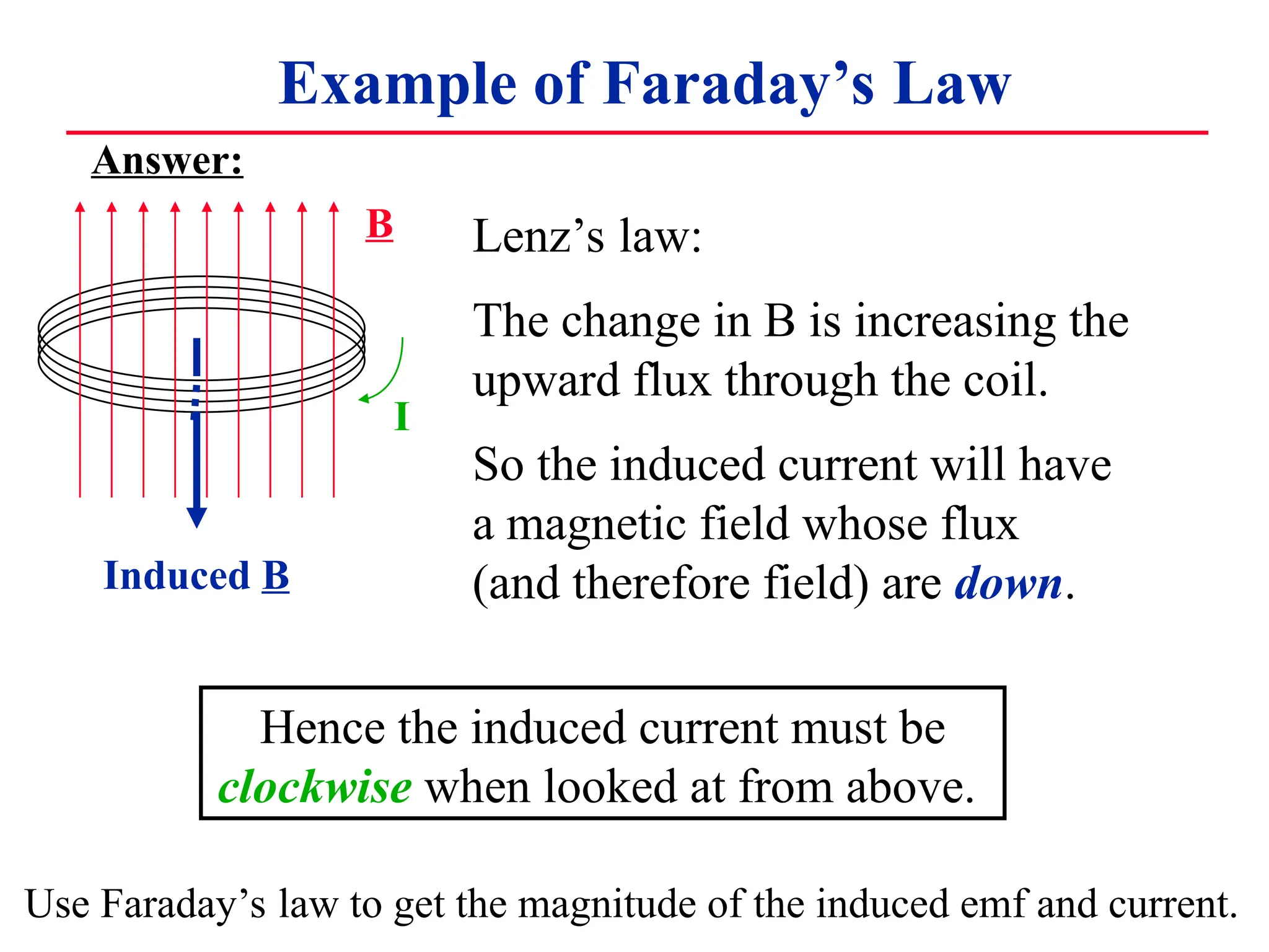
Example of Faraday’sLaw
B
Hence the induced current must be
clockwise when looked at from above.
Lenz’s law:
The change in B is increasing the
upward flux through the coil.
So the induced current will have
a magnetic field whose flux
(and therefore field) are down.
Induced B
I
Use Faraday’s law to get the magnitude of the induced emf and current.
Answer:
26.
B
Induced B
I
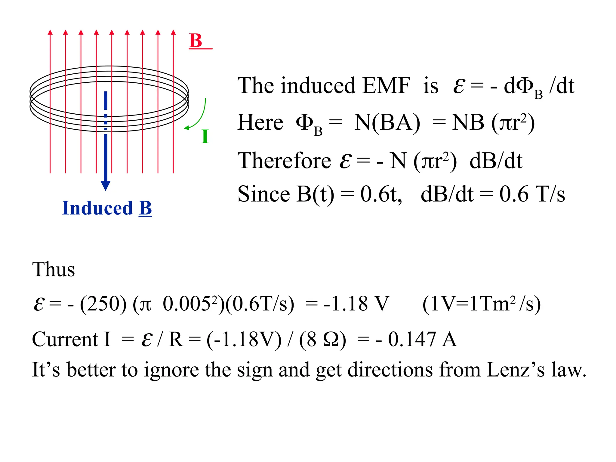
Thus
=- (250) (0.0052
)(0.6T/s) = -1.18 V (1V=1Tm2
/s)
Current I = / R = (-1.18V) / (8 ) = - 0.147 A
It’s better to ignore the sign and get directions from Lenz’s law.
The induced EMF is = - dB /dt
Here B = N(BA) = NB (r2
)
Therefore = - N (r2
)dB/dt
Since B(t) = 0.6t, dB/dt = 0.6 T/s
27.
x x xx x
x x Bx x x
x x x x x
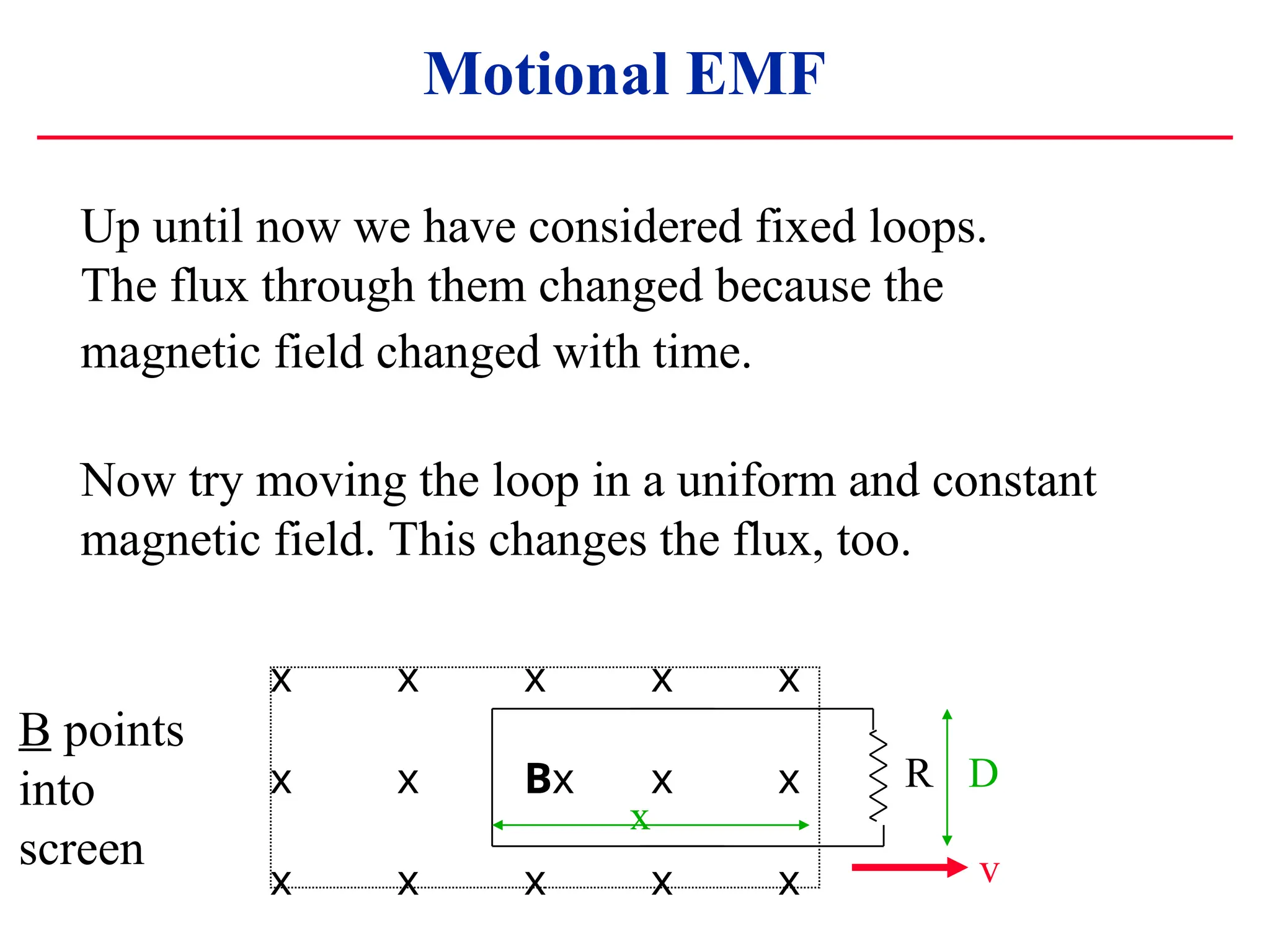
Up until now we have considered fixed loops.
The flux through them changed because the
magnetic field changed with time.
Now try moving the loop in a uniform and constant
magnetic field. This changes the flux, too.
Motional EMF
B points
into
screen
R
x
D
v
28.
x x xx x
x x Bx x x
x x x x x
R
x
D
v
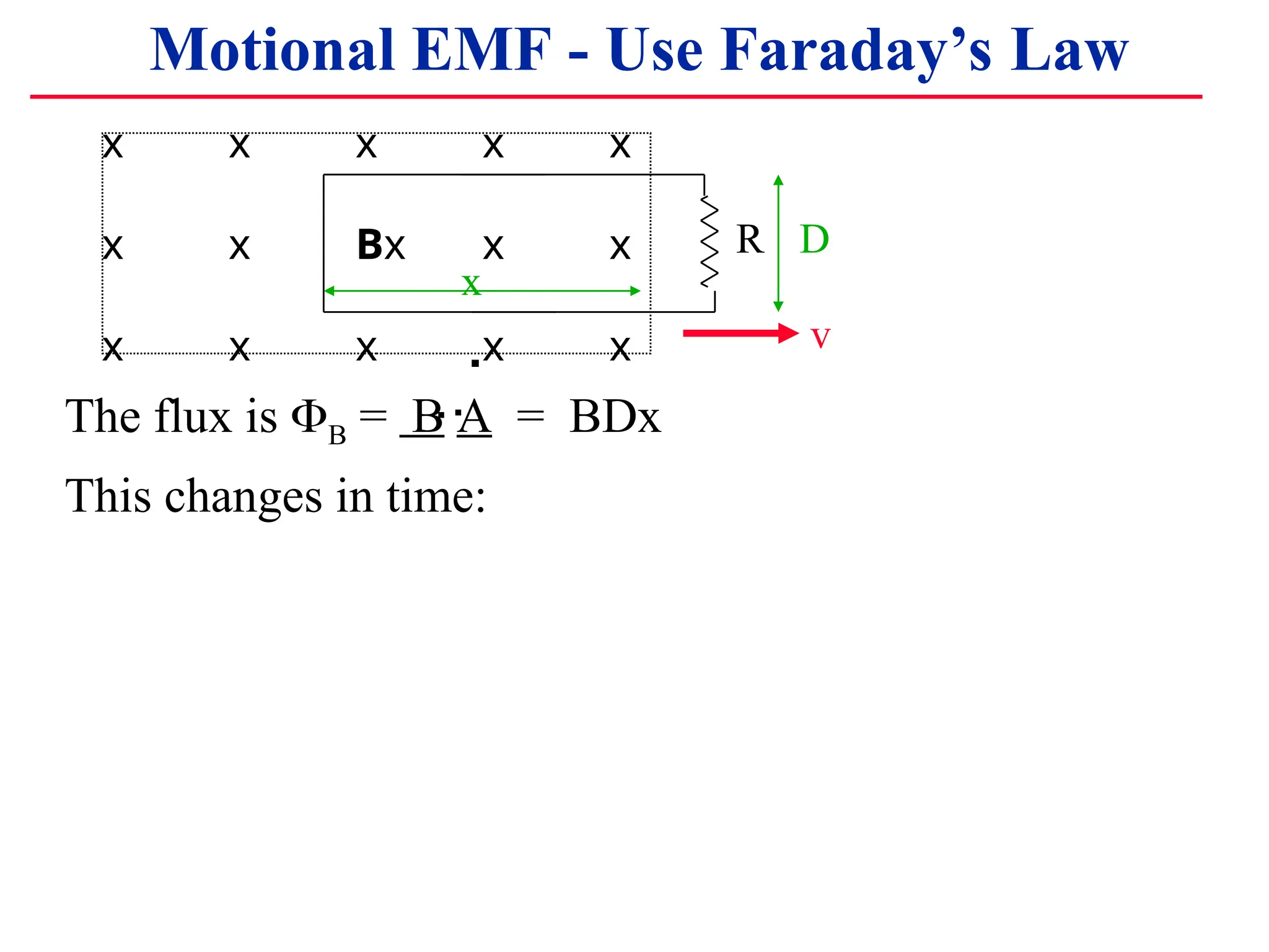
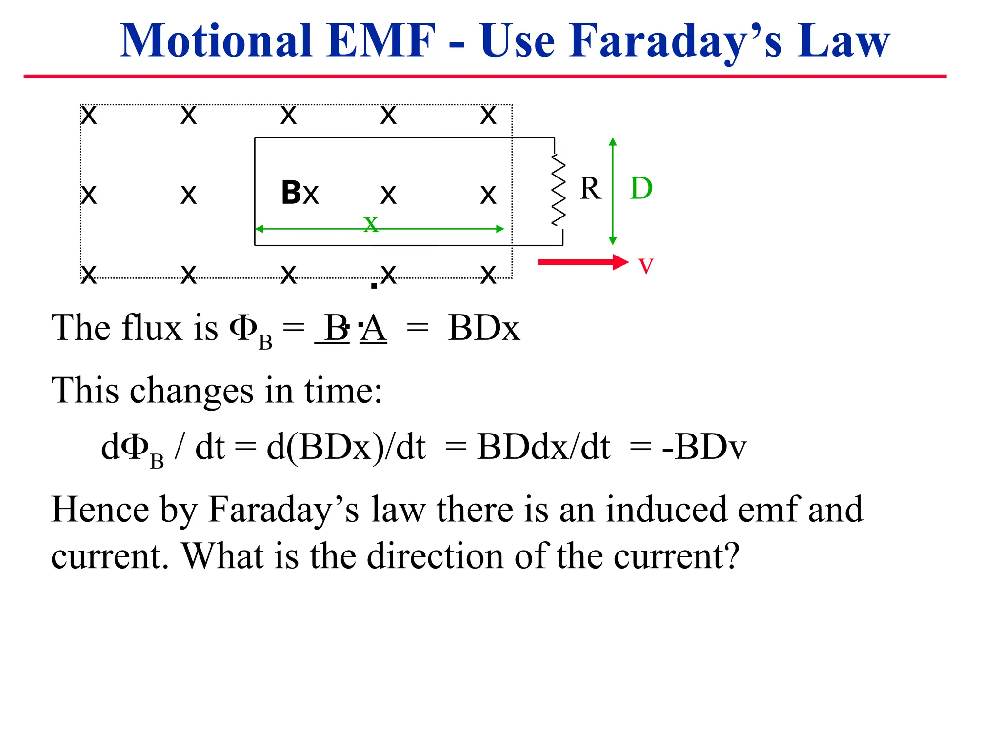
The flux is B = B A = BDx
This changes in time:
.
Motional EMF - Use Faraday’s Law
.
.
29.
The flux isB = B A = BDx
This changes in time:
dB / dt = d(BDx)/dt = BDdx/dt = -BDv
Hence by Faraday’s law there is an induced emf and
current. What is the direction of the current?
x x x x x
x x Bx x x
x x x x x
R
x
D
v
.
Motional EMF - Use Faraday’s Law
.
.
30.
x x xx x
x x Bx x x
x x x x x
R
x
D
v
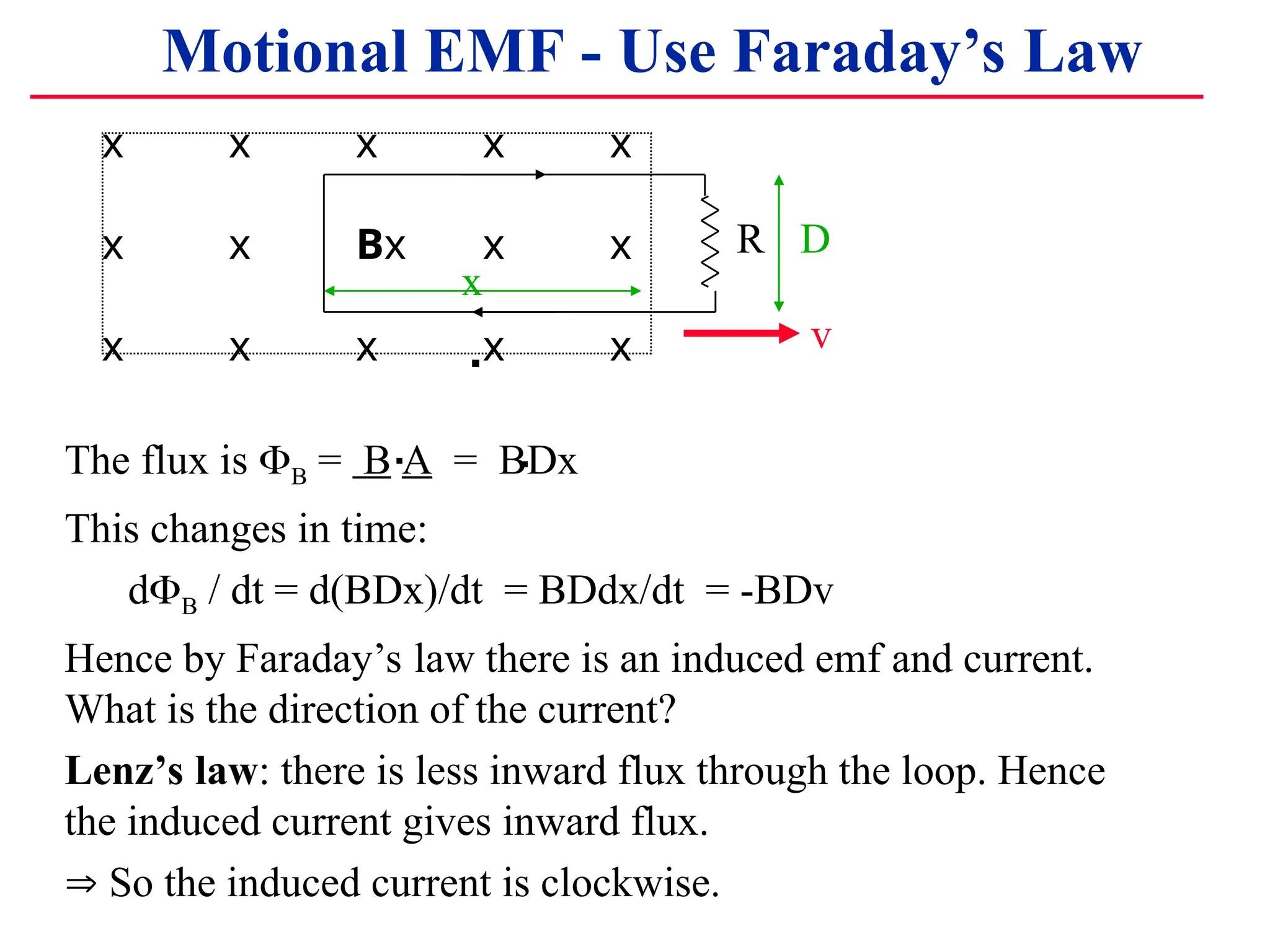
The flux is B = B A = BDx
This changes in time:
dB / dt = d(BDx)/dt = BDdx/dt = -BDv
Hence by Faraday’s law there is an induced emf and current.
What is the direction of the current?
Lenz’s law: there is less inward flux through the loop. Hence
the induced current gives inward flux.
So the induced current is clockwise.
.
Motional EMF - Use Faraday’s Law
.
.
31.
x x xx x
x x Bx x x
x x x x x
R
x
D
v
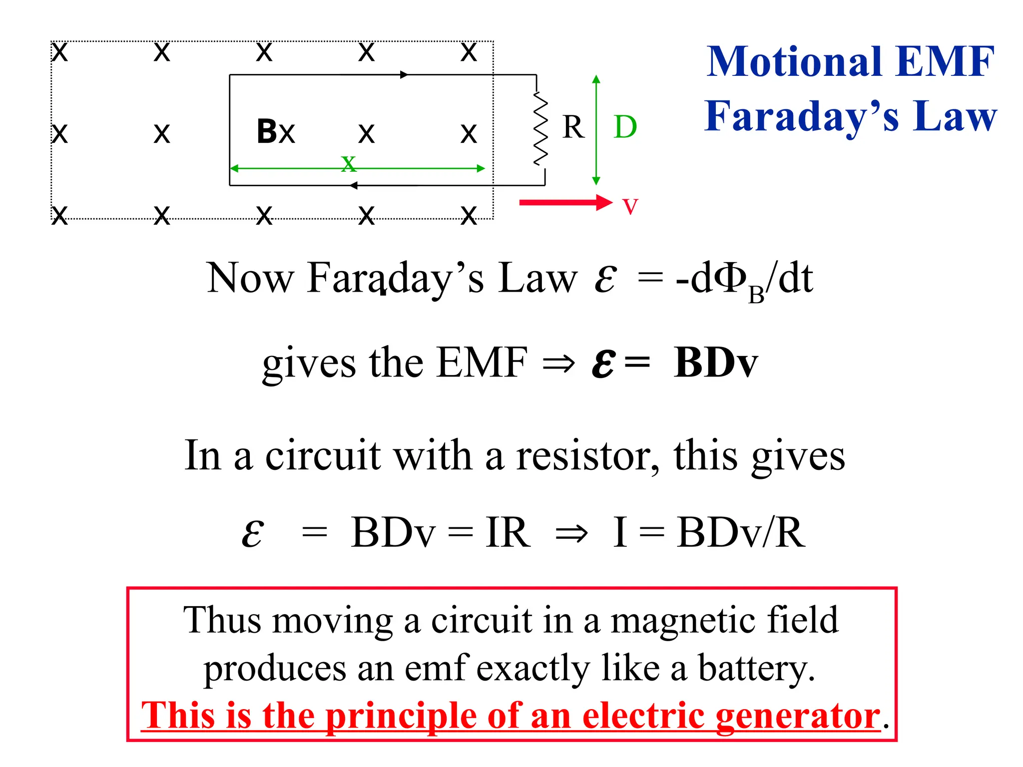
Now Faraday’s Law = -dB/dt
gives the EMF = BDv
In a circuit with a resistor, this gives
= BDv = IR I = BDv/R
Thus moving a circuit in a magnetic field
produces an emf exactly like a battery.
This is the principle of an electric generator.
.
Motional EMF
Faraday’s Law
32.
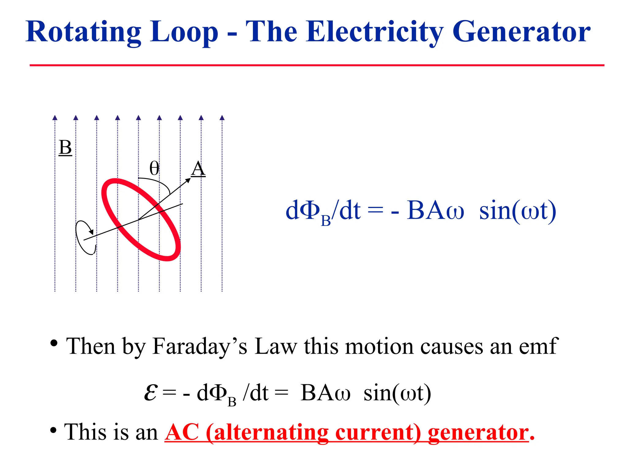
Rotating Loop -The Electric Generator
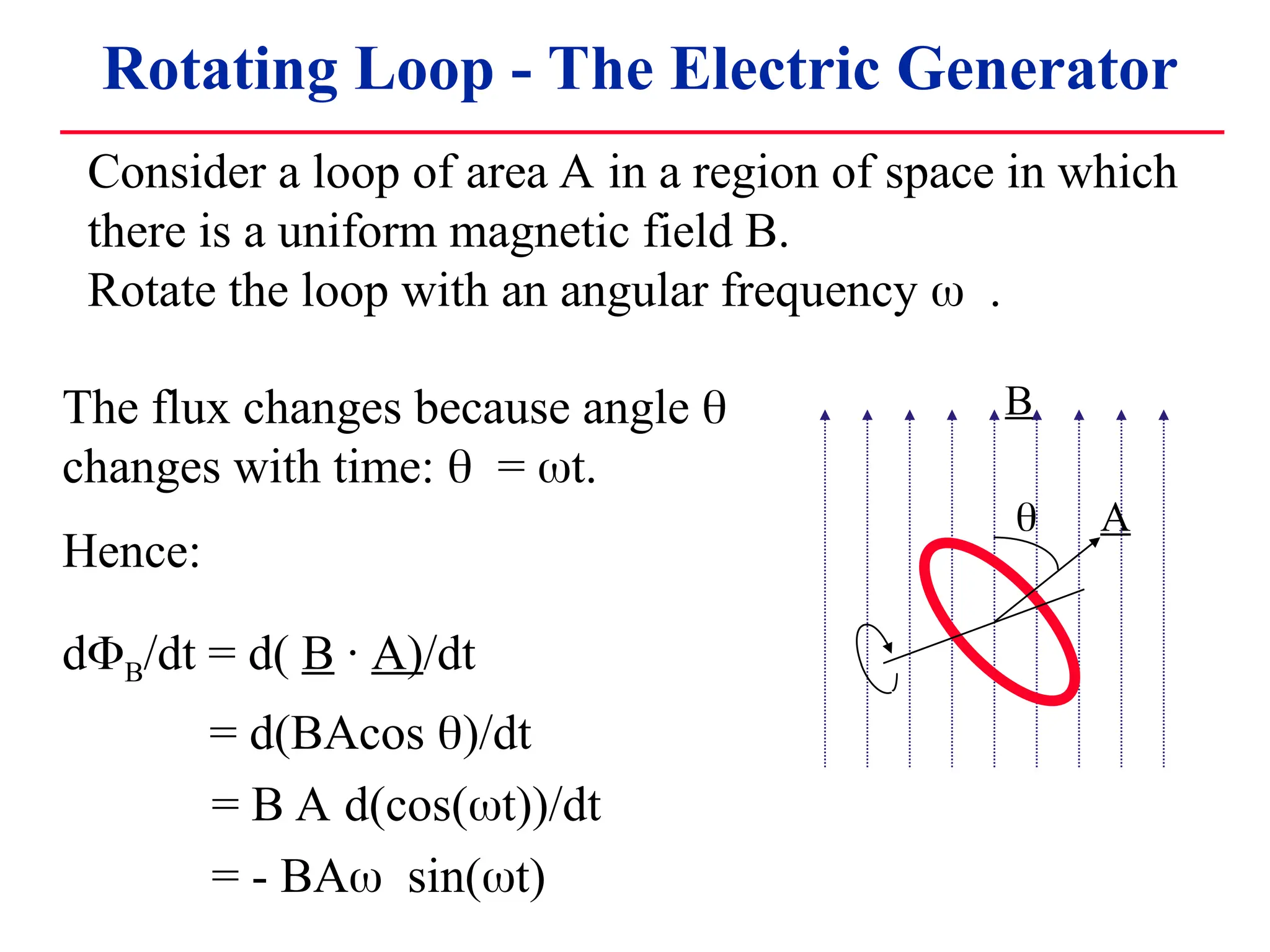
Consider a loop of area A in a region of space in which
there is a uniform magnetic field B.
Rotate the loop with an angular frequency .
A
B
The flux changes because angle
changes with time: = t.
Hence:
dB/dt = d( B · A)/dt
= d(BAcos )/dt
= B A d(cos(t))/dt
= - BAsin(t)
33.
• Then byFaraday’s Law this motion causes an emf
= - dB /dt = BAsin(t)
• This is an AC (alternating current) generator.
B
A
dB/dt = - BAsin(t)
Rotating Loop - The Electricity Generator
34.
A New Sourceof EMF
• If we have a conducting loop in a magnetic field, we
can create an EMF (like a battery) by changing the
value of B · A.
• This can be done by changing the area, by changing
the magnetic field, or the angle between them.
• We can use this source of EMF in electrical circuits in
the same way we used batteries.
• Remember we have to do work (mechanical energy)
to move the loop or to change B, to generate the EMF
(Nothing is for free).
35.
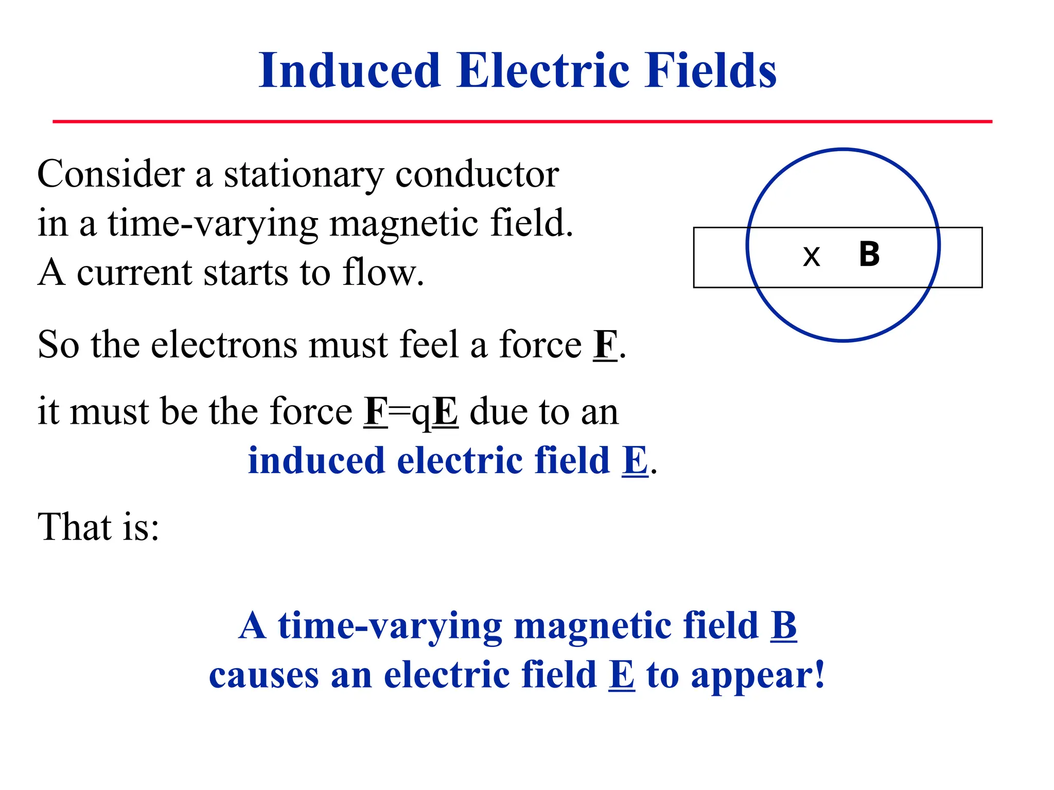
Consider a stationaryconductor
in a time-varying magnetic field.
A current starts to flow.
Induced Electric Fields
x B
So the electrons must feel a force F.
it must be the force F=qE due to an
induced electric field E.
That is:
A time-varying magnetic field B
causes an electric field E to appear!
36.
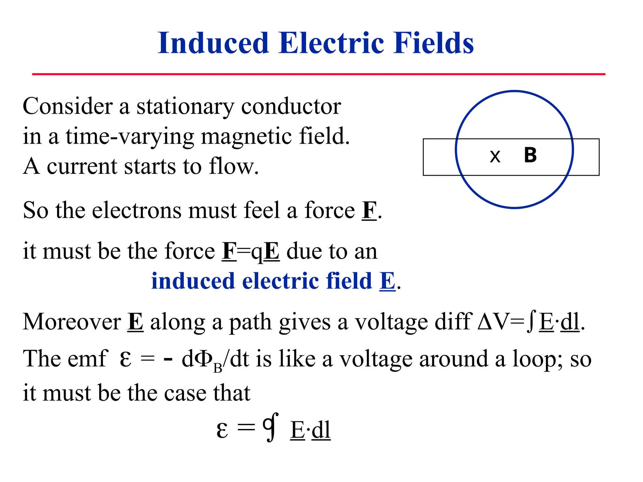
Consider a stationaryconductor
in a time-varying magnetic field.
A current starts to flow.
Induced Electric Fields
x B
So the electrons must feel a force F.
it must be the force F=qE due to an
induced electric field E.
Moreover E along a path gives a voltage diff V=E·dl.
The emf = - dB/dt is like a voltage around a loop; so
it must be the case that
= E·dl
o
37.
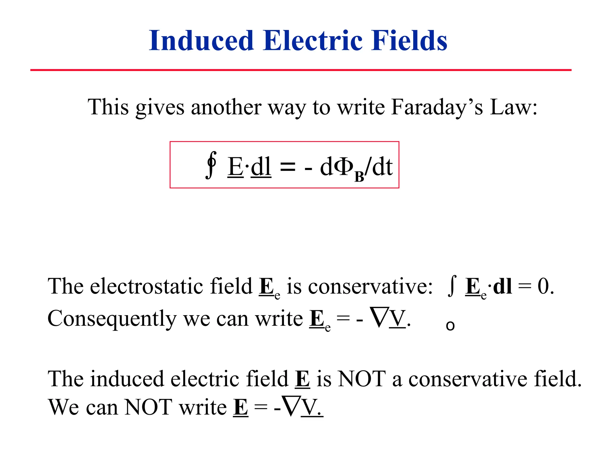
Induced Electric Fields
E·dl = - dB/dt
o
This gives another way to write Faraday’s Law:
The electrostatic field Ee is conservative: Ee·dl = 0.
Consequently we can write Ee = - V.
The induced electric field E is NOT a conservative field.
We can NOT write E = -V.
o
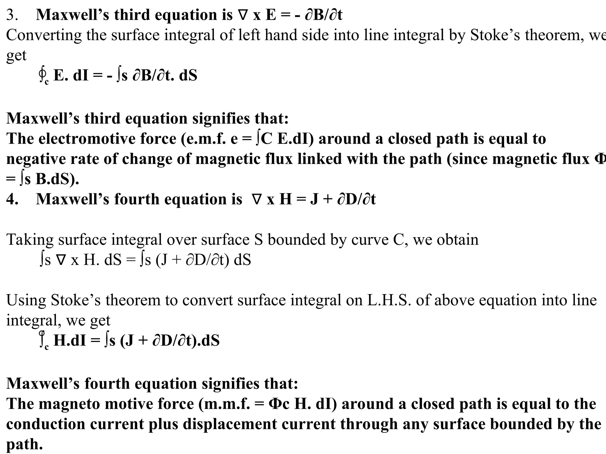
3. Maxwell’s thirdequation is x E = - ∂B/∂t
∇
Converting the surface integral of left hand side into line integral by Stoke’s theorem, we
get
∫c E. dI = - ∫s ∂B/∂t. dS
Maxwell’s third equation signifies that:
The electromotive force (e.m.f. e = ∫C E.dI) around a closed path is equal to
negative rate of change of magnetic flux linked with the path (since magnetic flux Φ
= ∫s B.dS).
4. Maxwell’s fourth equation is x H = J + ∂D/∂t
∇
Taking surface integral over surface S bounded by curve C, we obtain
∫s x H. dS = ∫s (J + ∂D/∂t) dS
∇
Using Stoke’s theorem to convert surface integral on L.H.S. of above equation into line
integral, we get
∫c H.dI = ∫s (J + ∂D/∂t).dS
Maxwell’s fourth equation signifies that:
The magneto motive force (m.m.f. = Φc H. dI) around a closed path is equal to the
conduction current plus displacement current through any surface bounded by the
path.

![Example of Faraday’s Law
B
Problem: Consider a coil of radius 5 cm with N = 250 turns.
A magnetic field B, passing through it,
changes in time: B(t)= 0.6 t [T] (t = time in seconds)
The total resistance of the coil is 8 .
What is the induced current ?
Use Lenz’s law to determine the
direction of the induced current.
Apply Faraday’s law to find the
emf and then the current.](https://image.slidesharecdn.com/electromagneticinduction-250524063750-e8cbda4d/75/Electro-Magnetic-Induction-ppt-basic-idea-about-EMI-24-2048.jpg)