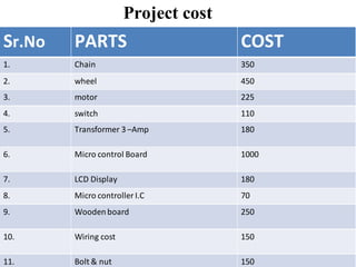
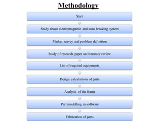
SlideShare a Scribd company logo
DESIGN AND DEVELOPMENT ON ELECTRO
MAGNETICAND AUTOMATICBREAKING
SYSTEM
GUIDED BY :- PROF.MANOJ P. RAJPARA
PREPARED BY: GROUP NO:-27
 RAJPUT VIPUL 11ME64
 PARAJAPATI NIKUL 12ME02
 MODI SAGAR 12ME17
 DARJI MILAN 12 ME18
CONTENT
Introduction
Project Principal
Literature Review
Types of brake
Component
Component design
Construction
 Future Scope
Advantage
Disadvantage
Application
 Work Planning
Reference
INTRODUCTION
In this project we have designed and establishment and
Electromagnetic disk braking system so as to have a future
alternative to traditional breaking systems. Electromagnetic disk
braking system slows an objects by creating an eddy current
through electromagnetic induction which create resistance. When
electromagnetic are used, control of the breaking action is made
possible by varying the strength of the magnetic field of the
electromagnets creates eddy currents in the discs. These eddy
currents generate an opposing magnetic field (Lenz's law), which
then resists the rotation of the discs, providing braking force. The
net result is to convert the motion of the rotors into heat in the
rotors.
Electro magnetic and auto breaking
system
designed to develop a new system that can solve this
problem where drivers may not brake manually but the
vehicles can stop automatically due to obstacles. This
project is about a system that can control braking system
for safety. Using ultrasonic as a ranging sensor, its
function based on ultrasonic wave. After transmit by
transmitter, the wave can reflect when obstacle detected
and receive by receiver. The main target for this project is,
car cans automatically braking due to obstacles when the
sensor senses the obstacles. The braking circuit function
is to brake the car automatically after received signal
from the sensor.
PRINCIPLE
As the disc enters the magnetic field a series of eddy currents will
be produced (as explained by Lenz‟s law). This produces a
magnetic field that will oppose the change brought about by the
rotating disc. If the magnetic field of the horseshoe magnet is
coming out of the page then the induced magnetic field will be
into the page. The induced current will be in a clockwise direction
to produce this field. This will bring the disc to a halt very quickly
and will result in a small amount of heat being produced by the
eddy currents.
PRINCIPLE
PRINCIPLE
LITERATURE REVIEW:
PAPER TITLE AUTHOR NAME OUTCOME
Innovative Electro
Magnetic Braking
System
Sevvel P1, Nirmal
Kannan V2, Mars
Mukesh S3
An Electromagnetic
Braking system uses
Magnetic force to engage
the brake, but the power
required for
braking is transmitted
manually. The
electromagnetic brakes
can be used in
commercial
vehicles by controlling
the current supplied to
produce the magnetic
flux. Making some
improvements in the
brakes it canbe used in
automobiles in future
PAPER TITLE AUTHOR NAME OUTCOME
ULTRASONIC CAR
BRAKING SYSTEM
ULTRASONIC CAR
BRAKING SYSTEM
MOHD SHAHRIZAN B.
SAHRI
An ultrasoniccar braking
system includes; an ultra
sonic wave emitter
provided in a front
portion of an automatic
braking
car producing and
emitting
ultrasonic waves
frontward in a
predetermined dista
nce in front of the car.
PAPER TITLE AUTHOR NAME OUTCOME
Fabrication of Auto-
Braking Sy
stem for Pre-Crash Safety
Using Sensor
Eung Soo Kim This module can
detect the distance
between front vehicle
anddriver’s vehicleto
keep a constant distance
using a sensor and
operatethe brake system
forcibly if the driver does
not decrease the speed
of car.
PAPER TITLE AUTHOR NAME OUTCOME
ANTILOCK BRAKING
SYSTEM
SahilJitesh1* ABS generally
offer advancedvehicle
control and minimize the
stopping distance in
slippery and dry surface,
conversely on loose
surface like gravel or
snow covered pavement,
ABS can significantly
increasebrakingdistance,
althoughstill improving
vehicle control.
TYPES OF BRAKE
DRUM BRAKE:
It consists of a brake drum which is concentric to the axle
hub whereas on the axle casing is mounted a back plate. The
back plate is made up of pressed steel sheet and it provides
support for the expander, anchor and brake shoes.
DISC BRAKE:
Disc brakes work using the same basic principle as the brakes
on a bicycle as the caliper pinches the wheel with pads on both
sides, it slows the vehicle.
AIR BRAKE :
Air brakes use standard hydraulic brake system components such
as braking lines, wheel cylinders and a slave cylinder similar to a
master cylinder to transmit the air-pressure-produced braking energy
to the wheel brakes. Air brakes are used frequently when greater
braking capacity is required.
HAND BRAKE :
Hand brakes are the parking or emergency brakes. They helps a
vehicle to park on a slope or during emergencies when primary
brakes are disabled. They works independently of primary brakes.
COMPONENTS USED
• DC motor (as engine)
• DC electromagnets
• Chain
• Pedals
• Relay
• Transformer
• Ultrasonic sensor
COMPONENT
1.DISC
The brake disc is the component of a
disc brake against which the brake
pads are applied. The material is
typically grey iron a form of cast
iron. The design of the disc varies
somewhat. Some are simply solid,
but others are hollowed out with fins
or vanes joining together the disc's
two contact surfaces (usually
included as part of a casting
process)..
Dc Motor
Dc motor is an
electric motor converts
electrical energy into
mechanical motion. The
reverse task that of
converting mechanical
motion into electrical
energy, is accomplished
by a generator or
dynamo. In many cases
the two devices are
identical except for their
application and minor
construction details.
Transformer
An electric current flowing in a
wire creates a magnetic field
around the wire (see drawing
below). To concentrate the
magnetic field, in an
electromagnet the wire is wound
into a coil, with many turns of
wire lying side by side. The
magnetic field of all the turns of
wire passes through the center of
the coil, creating a strong
magnetic field there.
Electromagnet
Electromagnets are very widely used in electric and
electromechanical devices, including:
 Motors and generators
• transformers
 Relays, including reed relays originally used in telephone
exchanges
• Electric bells
• Loudspeakers
 Magnetic recording and data storage equipment: tape recorders,
VCRs, hard disks
 Scientific instruments such as MRI machines and mass
spectrometers
 Particle accelerators
chain
A chain drive is a mechanism
for transferring mechanical
powerbetw two places, and is
common means of locomotion in
bicycles and motorcycles. It is
alsmotive source for many
different types ofmachinery.
Chain drives have existed as a
technology sinc. he third
century BC and have remained he
same in their basic design since
that time.
INFRARED PROXIMITY SENSOR
An infrared proximity sensor is a sensor
able to detect the presence of nearby objects
without any physical contact. A infrared
proximity sensor often emits an
electromagnetic field or a beam of
electromagnetic radition in(frared, for
instance), and looks for changes in the field
or return signal. The object being sensed is
often referred to as the infrared proximity
sensor's target. Different infrared proximity
sensor targets demand different sensors. For
example, a capacitive photoelectric
sensormight be suitable for a plastic target;
an inductiveinfrared proximity sensor always
requires a metal target.
LCD
A liquid-crystal display better known as (LCD) is a flat panal
display,electronic visual display or video displaythat uses the light
modulating properties of liquid crystals. Liquid crystals do not emit
light directly.
LCDs are used in a wide range of applications
including computer monitors, televisions, instrument
panels,aircraft cockpit displays, and signage. They are common in
consumer devices such as video players, gaming
devices, clocks, watches. calculators, and telephones, and have
replaced cathode ray tube (CRT) displays in most applications.
1.wheel
N1d=N2D
N2=80 RPM
2.disc
Centre distance between the pulleys= 32cm
Diameter of the driving pulley = 4.4cm=d
Diameter of the driven pulley = 5.5cm=D Speed
of the driving pulley = 100 rpm=N1
24volt
3.electromagnet
4. Wood bar
3-D Modeal
WORKING MODEAL
Project cost
Sr.No PARTS COST
1. Chain 350
2. wheel 450
3. motor 225
4. switch 110
5. Transformer 3 –Amp 180
6. Micro control Board 1000
7. LCD Display 180
8. Micro controller I.C 70
9. Woodenboard 250
10. Wiring cost 150
11. Bolt & nut 150
Sr. No PARTS COST
13. sensor 400
14. Maincable 20
TotalCost 3635
CONSTRUCTION
A horseshoe magnet (A-1) has a North and South Pole. If a
piece of Iron contacts both poles, a magnetic circuit is created.
In an electromagnetic brake, the North and South Pole is
created by a coil shell and a wound coil. In a brake, the
armature is being pulled against the brake field. (A-3) The
frictional contact, which is being controlled by the strength of
the magnetic field, is what causes the rotational motion to stop.
All of the torque comes from the magnetic attraction and
coefficient of friction between the steel of the armature and the
steel of the brake field. Example, if the brake was required to
have an extended time to stop or slip time, a low coefficient
material can be used.
FUTURE SCOPE
A revolutionary invention is made in the field of
brakes. The Electromagnetic brakes are excellent
replacement for conventional automobile brakes.The use
of Electromagnetic brakes can be done for lighter vehicles
also. With some modification, a regenerative braking
system can be equipped with the Electromagnetic brakes.
The Electromagnetic brakes are the future of automobile
brakes.
CONCLUSION
The prototype work “VEHICLE SPEED CONTROL AND
AUTOMATIC BRAKING SYSTEM” has been successfully
designed and tested. Integrating features of all the components
have used developed it .Presence of every module has been
reasoned out and placed carefully thus contributing the best
working of the unit. Secondly using highly advanced IC‟s and
with the help of growing technology the project has been
implemented successfully
Electromagnetic brakes can be used for modern Light as
well as heavy vehicles. They give better performance with
enhanced safety.
APPLICATION
• Commercial vehicle
• Building lift
• Industries machine
ADVANTAGES
• Electromagnetic brakes are more durable.
• Electromagnetic brakes have a longer life span.
• Electromagnetic brakes are much more effective.
• Electromagnetic breaks works totally frictionless.
• Better cooling of brakes.
• There is less amount of wear.
• Maintenance required is negligible.
• Auto brakes are more durable.
• Auto brakes have a longer life span.
• Auto brakes are much more effective.
• Auto breaks works totally frictionless.
• Maintenance required is negligible.
DISADVANTAGES
• Battery low this time is not working
• Electronic Control Module in side fault that time break not
working
• A special spring mechanism needs to be provided for the quick
return of the brake shoe.
• Dependence on battery power to energize the brake system
drains down the battery much faster.
Methodology
Start
Study about electromagnetic and auto breaking system
Market survey and problem definition
Study of research paper an literature review
List of required equipments
Design calculations of parts
Analysis of the frame
Part modelling in software
Fabrication of parts
Reference
1. H. Van Oostveen and R. Siezen, “ErfahrungenmitPermanentmag-net-
Schienenbremsen”, GlasersAnnalen, Nr 12, S. 613-617, 1997.
2. Biro, O. and Preis, K., „„Finite element analysis of 3-D eddycurrent,‟‟
IEEE Transactions onMagnetics, Vol. 26, No. 2, pp. 418–423,Mar, 1990.
3. Ohyma, T., „„Adhesion at higher speeds, its basic characteristic, its
improvement and somerelated problem,‟‟ Japanese Railway Engineering,
Vol. 108, 1988.
4. A B Sharkawy (2010), “Genetic FuzzySelf-tuning PID Controllers for
Antilock
Braking Systems” EngineeringApplications of ArtificialIntelligence,Vol.
23, pp. 1041-1052.
5. A Poursamad (2009), “AdaptiveFeedback Linearization Control ofAntilock
Bracking System Using NeuralNetworks”, Mechatronics, Vol. 19, pp.
767-773.
Thank You

More Related Content

What's hot

Electromagnetic braking system group 14
Electromagnetic  braking system group 14Electromagnetic  braking system group 14
Electromagnetic braking system group 14
Nitesh Prasad
 
electro magnetic breaking
electro magnetic breakingelectro magnetic breaking
electro magnetic breaking
ganesh vakada
 
Electro magnetic brake
Electro  magnetic brakeElectro  magnetic brake
Electro magnetic brake
binapallinaveen
 
Regenerative Braking System by ASLAM
Regenerative Braking System by ASLAMRegenerative Braking System by ASLAM
Regenerative Braking System by ASLAM
MD ASLAM HUSSAIN
 
Electromagnetic braking
Electromagnetic brakingElectromagnetic braking
Electromagnetic brakingSurya Prakash
 
Braking system
Braking systemBraking system
Braking system
Ak355
 
Regenerative Braking System
Regenerative Braking SystemRegenerative Braking System
Regenerative Braking System
Hassan Raza
 
Ppt on project_ELECTOMAGNETIC_BRAKING_SYSTEM
Ppt on project_ELECTOMAGNETIC_BRAKING_SYSTEMPpt on project_ELECTOMAGNETIC_BRAKING_SYSTEM
Ppt on project_ELECTOMAGNETIC_BRAKING_SYSTEM
ANUPAM SINGH
 
Regenerative braking system
Regenerative braking systemRegenerative braking system
Regenerative braking system
Christal CADD Technology
 
Electromagnetic Regenerative Shock Absorbers
Electromagnetic Regenerative Shock AbsorbersElectromagnetic Regenerative Shock Absorbers
Electromagnetic Regenerative Shock Absorbers
Noufal Nizar
 
Road power generation
Road power generationRoad power generation
Road power generation
NAZEEMARAFIQ
 
REGENERATIVE SHOCK ABSORBER
REGENERATIVE SHOCK ABSORBERREGENERATIVE SHOCK ABSORBER
REGENERATIVE SHOCK ABSORBERNISHANT SARASWAT
 
ULTRASONIC MOTOR
ULTRASONIC MOTOR  ULTRASONIC MOTOR
ULTRASONIC MOTOR
AVINASH MEENA
 
Power generating using Regenerative Braking system ppt
Power generating using Regenerative Braking system ppt Power generating using Regenerative Braking system ppt
Power generating using Regenerative Braking system ppt
dxamit90
 
A seminar report on maglev train
A seminar report on maglev trainA seminar report on maglev train
A seminar report on maglev train
007skpk
 
Seminar report on ultrasonic motor
Seminar report on ultrasonic motorSeminar report on ultrasonic motor
Seminar report on ultrasonic motor
Ashutosh Srivastava
 
Regenerative braking system
Regenerative braking systemRegenerative braking system
Regenerative braking system
Rohit Nair
 
Hybrid two wheeler2
Hybrid two wheeler2Hybrid two wheeler2
Hybrid two wheeler2Rajesh Sl
 
Kinetic energy recovery system ppt
Kinetic energy recovery system pptKinetic energy recovery system ppt
Kinetic energy recovery system ppt
gautam khillare
 
Regenerative breaking system
 Regenerative breaking system Regenerative breaking system
Regenerative breaking system
ABIRAJ R
 

What's hot (20)

Electromagnetic braking system group 14
Electromagnetic  braking system group 14Electromagnetic  braking system group 14
Electromagnetic braking system group 14
 
electro magnetic breaking
electro magnetic breakingelectro magnetic breaking
electro magnetic breaking
 
Electro magnetic brake
Electro  magnetic brakeElectro  magnetic brake
Electro magnetic brake
 
Regenerative Braking System by ASLAM
Regenerative Braking System by ASLAMRegenerative Braking System by ASLAM
Regenerative Braking System by ASLAM
 
Electromagnetic braking
Electromagnetic brakingElectromagnetic braking
Electromagnetic braking
 
Braking system
Braking systemBraking system
Braking system
 
Regenerative Braking System
Regenerative Braking SystemRegenerative Braking System
Regenerative Braking System
 
Ppt on project_ELECTOMAGNETIC_BRAKING_SYSTEM
Ppt on project_ELECTOMAGNETIC_BRAKING_SYSTEMPpt on project_ELECTOMAGNETIC_BRAKING_SYSTEM
Ppt on project_ELECTOMAGNETIC_BRAKING_SYSTEM
 
Regenerative braking system
Regenerative braking systemRegenerative braking system
Regenerative braking system
 
Electromagnetic Regenerative Shock Absorbers
Electromagnetic Regenerative Shock AbsorbersElectromagnetic Regenerative Shock Absorbers
Electromagnetic Regenerative Shock Absorbers
 
Road power generation
Road power generationRoad power generation
Road power generation
 
REGENERATIVE SHOCK ABSORBER
REGENERATIVE SHOCK ABSORBERREGENERATIVE SHOCK ABSORBER
REGENERATIVE SHOCK ABSORBER
 
ULTRASONIC MOTOR
ULTRASONIC MOTOR  ULTRASONIC MOTOR
ULTRASONIC MOTOR
 
Power generating using Regenerative Braking system ppt
Power generating using Regenerative Braking system ppt Power generating using Regenerative Braking system ppt
Power generating using Regenerative Braking system ppt
 
A seminar report on maglev train
A seminar report on maglev trainA seminar report on maglev train
A seminar report on maglev train
 
Seminar report on ultrasonic motor
Seminar report on ultrasonic motorSeminar report on ultrasonic motor
Seminar report on ultrasonic motor
 
Regenerative braking system
Regenerative braking systemRegenerative braking system
Regenerative braking system
 
Hybrid two wheeler2
Hybrid two wheeler2Hybrid two wheeler2
Hybrid two wheeler2
 
Kinetic energy recovery system ppt
Kinetic energy recovery system pptKinetic energy recovery system ppt
Kinetic energy recovery system ppt
 
Regenerative breaking system
 Regenerative breaking system Regenerative breaking system
Regenerative breaking system
 

Similar to Embs 2

Seminar amit yadav 2
Seminar amit yadav 2Seminar amit yadav 2
Seminar amit yadav 2
Amit Yadav
 
Eddy Current Braking System
Eddy Current Braking SystemEddy Current Braking System
Eddy Current Braking System
Shubham Dubey
 
eddycurrentbreaking-131015080857-phpapp01.pptx
eddycurrentbreaking-131015080857-phpapp01.pptxeddycurrentbreaking-131015080857-phpapp01.pptx
eddycurrentbreaking-131015080857-phpapp01.pptx
Poooi2
 
147753824 multipurpose-machines-using-scotch-yoke-mechanism (1)
147753824 multipurpose-machines-using-scotch-yoke-mechanism (1)147753824 multipurpose-machines-using-scotch-yoke-mechanism (1)
147753824 multipurpose-machines-using-scotch-yoke-mechanism (1)
shushay hailu
 
Eddy current brakes
Eddy current brakesEddy current brakes
Eddy current brakes
Rahul Aman
 
IRJET- Implementation of Lenz Law for the Application of Electromagnetic ...
IRJET-  	  Implementation of Lenz Law for the Application of Electromagnetic ...IRJET-  	  Implementation of Lenz Law for the Application of Electromagnetic ...
IRJET- Implementation of Lenz Law for the Application of Electromagnetic ...
IRJET Journal
 
Eddycurrentbrakes
EddycurrentbrakesEddycurrentbrakes
Eddycurrentbrakes
Logan Patnaik
 
ELECTROMAGNETIC_BRAKING_SYSTEM.pptx
ELECTROMAGNETIC_BRAKING_SYSTEM.pptxELECTROMAGNETIC_BRAKING_SYSTEM.pptx
ELECTROMAGNETIC_BRAKING_SYSTEM.pptx
MuhammadZulqarnain343511
 
ULTRASONIC MOTOR.pdf
ULTRASONIC MOTOR.pdfULTRASONIC MOTOR.pdf
ULTRASONIC MOTOR.pdf
mrvishnuraj1999
 
Eddy Current Braking System
Eddy Current Braking SystemEddy Current Braking System
Eddy Current Braking System
Aniket Sunil Mutekar
 
power-generating-shock-absorber-Seminar-Final.pptx
power-generating-shock-absorber-Seminar-Final.pptxpower-generating-shock-absorber-Seminar-Final.pptx
power-generating-shock-absorber-Seminar-Final.pptx
sonamthakur625
 
pptonprojecttopicebs-df
pptonprojecttopicebs-dfpptonprojecttopicebs-df
pptonprojecttopicebs-df
ShashidharaTV2
 
1
11
RGPV EX503 UNIT III
RGPV EX503 UNIT IIIRGPV EX503 UNIT III
RGPV EX503 UNIT III
Mani Deep Dutt
 
Ee2537473768
Ee2537473768Ee2537473768
Ee2537473768brindham
 
Eddy current brake
Eddy  current  brakeEddy  current  brake
Eddy current brake
Pintu Khan
 
ULTRASONIC MOTOR(ARJUN)
ULTRASONIC MOTOR(ARJUN)ULTRASONIC MOTOR(ARJUN)
ULTRASONIC MOTOR(ARJUN)
ARJUN SIBI
 
Electro magnetic breaking system BY G.DINESHPIRAN
Electro magnetic breaking system BY G.DINESHPIRANElectro magnetic breaking system BY G.DINESHPIRAN
Electro magnetic breaking system BY G.DINESHPIRAN
Dinesh Piran-Gdp
 

Similar to Embs 2 (20)

Eddy current braking
Eddy current brakingEddy current braking
Eddy current braking
 
Seminar amit yadav 2
Seminar amit yadav 2Seminar amit yadav 2
Seminar amit yadav 2
 
Eddy Current Braking System
Eddy Current Braking SystemEddy Current Braking System
Eddy Current Braking System
 
eddycurrentbreaking-131015080857-phpapp01.pptx
eddycurrentbreaking-131015080857-phpapp01.pptxeddycurrentbreaking-131015080857-phpapp01.pptx
eddycurrentbreaking-131015080857-phpapp01.pptx
 
147753824 multipurpose-machines-using-scotch-yoke-mechanism (1)
147753824 multipurpose-machines-using-scotch-yoke-mechanism (1)147753824 multipurpose-machines-using-scotch-yoke-mechanism (1)
147753824 multipurpose-machines-using-scotch-yoke-mechanism (1)
 
Eddy current brakes
Eddy current brakesEddy current brakes
Eddy current brakes
 
Maxon motors
Maxon motorsMaxon motors
Maxon motors
 
IRJET- Implementation of Lenz Law for the Application of Electromagnetic ...
IRJET-  	  Implementation of Lenz Law for the Application of Electromagnetic ...IRJET-  	  Implementation of Lenz Law for the Application of Electromagnetic ...
IRJET- Implementation of Lenz Law for the Application of Electromagnetic ...
 
Eddycurrentbrakes
EddycurrentbrakesEddycurrentbrakes
Eddycurrentbrakes
 
ELECTROMAGNETIC_BRAKING_SYSTEM.pptx
ELECTROMAGNETIC_BRAKING_SYSTEM.pptxELECTROMAGNETIC_BRAKING_SYSTEM.pptx
ELECTROMAGNETIC_BRAKING_SYSTEM.pptx
 
ULTRASONIC MOTOR.pdf
ULTRASONIC MOTOR.pdfULTRASONIC MOTOR.pdf
ULTRASONIC MOTOR.pdf
 
Eddy Current Braking System
Eddy Current Braking SystemEddy Current Braking System
Eddy Current Braking System
 
power-generating-shock-absorber-Seminar-Final.pptx
power-generating-shock-absorber-Seminar-Final.pptxpower-generating-shock-absorber-Seminar-Final.pptx
power-generating-shock-absorber-Seminar-Final.pptx
 
pptonprojecttopicebs-df
pptonprojecttopicebs-dfpptonprojecttopicebs-df
pptonprojecttopicebs-df
 
1
11
1
 
RGPV EX503 UNIT III
RGPV EX503 UNIT IIIRGPV EX503 UNIT III
RGPV EX503 UNIT III
 
Ee2537473768
Ee2537473768Ee2537473768
Ee2537473768
 
Eddy current brake
Eddy  current  brakeEddy  current  brake
Eddy current brake
 
ULTRASONIC MOTOR(ARJUN)
ULTRASONIC MOTOR(ARJUN)ULTRASONIC MOTOR(ARJUN)
ULTRASONIC MOTOR(ARJUN)
 
Electro magnetic breaking system BY G.DINESHPIRAN
Electro magnetic breaking system BY G.DINESHPIRANElectro magnetic breaking system BY G.DINESHPIRAN
Electro magnetic breaking system BY G.DINESHPIRAN
 

Recently uploaded

Halogenation process of chemical process industries
Halogenation process of chemical process industriesHalogenation process of chemical process industries
Halogenation process of chemical process industries
MuhammadTufail242431
 
LIGA(E)11111111111111111111111111111111111111111.ppt
LIGA(E)11111111111111111111111111111111111111111.pptLIGA(E)11111111111111111111111111111111111111111.ppt
LIGA(E)11111111111111111111111111111111111111111.ppt
ssuser9bd3ba
 
Cosmetic shop management system project report.pdf
Cosmetic shop management system project report.pdfCosmetic shop management system project report.pdf
Cosmetic shop management system project report.pdf
Kamal Acharya
 
Gen AI Study Jams _ For the GDSC Leads in India.pdf
Gen AI Study Jams _ For the GDSC Leads in India.pdfGen AI Study Jams _ For the GDSC Leads in India.pdf
Gen AI Study Jams _ For the GDSC Leads in India.pdf
gdsczhcet
 
在线办理(ANU毕业证书)澳洲国立大学毕业证录取通知书一模一样
在线办理(ANU毕业证书)澳洲国立大学毕业证录取通知书一模一样在线办理(ANU毕业证书)澳洲国立大学毕业证录取通知书一模一样
在线办理(ANU毕业证书)澳洲国立大学毕业证录取通知书一模一样
obonagu
 
Pile Foundation by Venkatesh Taduvai (Sub Geotechnical Engineering II)-conver...
Pile Foundation by Venkatesh Taduvai (Sub Geotechnical Engineering II)-conver...Pile Foundation by Venkatesh Taduvai (Sub Geotechnical Engineering II)-conver...
Pile Foundation by Venkatesh Taduvai (Sub Geotechnical Engineering II)-conver...
AJAYKUMARPUND1
 
Railway Signalling Principles Edition 3.pdf
Railway Signalling Principles Edition 3.pdfRailway Signalling Principles Edition 3.pdf
Railway Signalling Principles Edition 3.pdf
TeeVichai
 
power quality voltage fluctuation UNIT - I.pptx
power quality voltage fluctuation UNIT - I.pptxpower quality voltage fluctuation UNIT - I.pptx
power quality voltage fluctuation UNIT - I.pptx
ViniHema
 
Forklift Classes Overview by Intella Parts
Forklift Classes Overview by Intella PartsForklift Classes Overview by Intella Parts
Forklift Classes Overview by Intella Parts
Intella Parts
 
H.Seo, ICLR 2024, MLILAB, KAIST AI.pdf
H.Seo,  ICLR 2024, MLILAB,  KAIST AI.pdfH.Seo,  ICLR 2024, MLILAB,  KAIST AI.pdf
H.Seo, ICLR 2024, MLILAB, KAIST AI.pdf
MLILAB
 
MCQ Soil mechanics questions (Soil shear strength).pdf
MCQ Soil mechanics questions (Soil shear strength).pdfMCQ Soil mechanics questions (Soil shear strength).pdf
MCQ Soil mechanics questions (Soil shear strength).pdf
Osamah Alsalih
 
ASME IX(9) 2007 Full Version .pdf
ASME IX(9)  2007 Full Version       .pdfASME IX(9)  2007 Full Version       .pdf
ASME IX(9) 2007 Full Version .pdf
AhmedHussein950959
 
Design and Analysis of Algorithms-DP,Backtracking,Graphs,B&B
Design and Analysis of Algorithms-DP,Backtracking,Graphs,B&BDesign and Analysis of Algorithms-DP,Backtracking,Graphs,B&B
Design and Analysis of Algorithms-DP,Backtracking,Graphs,B&B
Sreedhar Chowdam
 
Democratizing Fuzzing at Scale by Abhishek Arya
Democratizing Fuzzing at Scale by Abhishek AryaDemocratizing Fuzzing at Scale by Abhishek Arya
Democratizing Fuzzing at Scale by Abhishek Arya
abh.arya
 
J.Yang, ICLR 2024, MLILAB, KAIST AI.pdf
J.Yang,  ICLR 2024, MLILAB, KAIST AI.pdfJ.Yang,  ICLR 2024, MLILAB, KAIST AI.pdf
J.Yang, ICLR 2024, MLILAB, KAIST AI.pdf
MLILAB
 
DESIGN A COTTON SEED SEPARATION MACHINE.docx
DESIGN A COTTON SEED SEPARATION MACHINE.docxDESIGN A COTTON SEED SEPARATION MACHINE.docx
DESIGN A COTTON SEED SEPARATION MACHINE.docx
FluxPrime1
 
road safety engineering r s e unit 3.pdf
road safety engineering  r s e unit 3.pdfroad safety engineering  r s e unit 3.pdf
road safety engineering r s e unit 3.pdf
VENKATESHvenky89705
 
COLLEGE BUS MANAGEMENT SYSTEM PROJECT REPORT.pdf
COLLEGE BUS MANAGEMENT SYSTEM PROJECT REPORT.pdfCOLLEGE BUS MANAGEMENT SYSTEM PROJECT REPORT.pdf
COLLEGE BUS MANAGEMENT SYSTEM PROJECT REPORT.pdf
Kamal Acharya
 
block diagram and signal flow graph representation
block diagram and signal flow graph representationblock diagram and signal flow graph representation
block diagram and signal flow graph representation
Divya Somashekar
 
Automobile Management System Project Report.pdf
Automobile Management System Project Report.pdfAutomobile Management System Project Report.pdf
Automobile Management System Project Report.pdf
Kamal Acharya
 

Recently uploaded (20)

Halogenation process of chemical process industries
Halogenation process of chemical process industriesHalogenation process of chemical process industries
Halogenation process of chemical process industries
 
LIGA(E)11111111111111111111111111111111111111111.ppt
LIGA(E)11111111111111111111111111111111111111111.pptLIGA(E)11111111111111111111111111111111111111111.ppt
LIGA(E)11111111111111111111111111111111111111111.ppt
 
Cosmetic shop management system project report.pdf
Cosmetic shop management system project report.pdfCosmetic shop management system project report.pdf
Cosmetic shop management system project report.pdf
 
Gen AI Study Jams _ For the GDSC Leads in India.pdf
Gen AI Study Jams _ For the GDSC Leads in India.pdfGen AI Study Jams _ For the GDSC Leads in India.pdf
Gen AI Study Jams _ For the GDSC Leads in India.pdf
 
在线办理(ANU毕业证书)澳洲国立大学毕业证录取通知书一模一样
在线办理(ANU毕业证书)澳洲国立大学毕业证录取通知书一模一样在线办理(ANU毕业证书)澳洲国立大学毕业证录取通知书一模一样
在线办理(ANU毕业证书)澳洲国立大学毕业证录取通知书一模一样
 
Pile Foundation by Venkatesh Taduvai (Sub Geotechnical Engineering II)-conver...
Pile Foundation by Venkatesh Taduvai (Sub Geotechnical Engineering II)-conver...Pile Foundation by Venkatesh Taduvai (Sub Geotechnical Engineering II)-conver...
Pile Foundation by Venkatesh Taduvai (Sub Geotechnical Engineering II)-conver...
 
Railway Signalling Principles Edition 3.pdf
Railway Signalling Principles Edition 3.pdfRailway Signalling Principles Edition 3.pdf
Railway Signalling Principles Edition 3.pdf
 
power quality voltage fluctuation UNIT - I.pptx
power quality voltage fluctuation UNIT - I.pptxpower quality voltage fluctuation UNIT - I.pptx
power quality voltage fluctuation UNIT - I.pptx
 
Forklift Classes Overview by Intella Parts
Forklift Classes Overview by Intella PartsForklift Classes Overview by Intella Parts
Forklift Classes Overview by Intella Parts
 
H.Seo, ICLR 2024, MLILAB, KAIST AI.pdf
H.Seo,  ICLR 2024, MLILAB,  KAIST AI.pdfH.Seo,  ICLR 2024, MLILAB,  KAIST AI.pdf
H.Seo, ICLR 2024, MLILAB, KAIST AI.pdf
 
MCQ Soil mechanics questions (Soil shear strength).pdf
MCQ Soil mechanics questions (Soil shear strength).pdfMCQ Soil mechanics questions (Soil shear strength).pdf
MCQ Soil mechanics questions (Soil shear strength).pdf
 
ASME IX(9) 2007 Full Version .pdf
ASME IX(9)  2007 Full Version       .pdfASME IX(9)  2007 Full Version       .pdf
ASME IX(9) 2007 Full Version .pdf
 
Design and Analysis of Algorithms-DP,Backtracking,Graphs,B&B
Design and Analysis of Algorithms-DP,Backtracking,Graphs,B&BDesign and Analysis of Algorithms-DP,Backtracking,Graphs,B&B
Design and Analysis of Algorithms-DP,Backtracking,Graphs,B&B
 
Democratizing Fuzzing at Scale by Abhishek Arya
Democratizing Fuzzing at Scale by Abhishek AryaDemocratizing Fuzzing at Scale by Abhishek Arya
Democratizing Fuzzing at Scale by Abhishek Arya
 
J.Yang, ICLR 2024, MLILAB, KAIST AI.pdf
J.Yang,  ICLR 2024, MLILAB, KAIST AI.pdfJ.Yang,  ICLR 2024, MLILAB, KAIST AI.pdf
J.Yang, ICLR 2024, MLILAB, KAIST AI.pdf
 
DESIGN A COTTON SEED SEPARATION MACHINE.docx
DESIGN A COTTON SEED SEPARATION MACHINE.docxDESIGN A COTTON SEED SEPARATION MACHINE.docx
DESIGN A COTTON SEED SEPARATION MACHINE.docx
 
road safety engineering r s e unit 3.pdf
road safety engineering  r s e unit 3.pdfroad safety engineering  r s e unit 3.pdf
road safety engineering r s e unit 3.pdf
 
COLLEGE BUS MANAGEMENT SYSTEM PROJECT REPORT.pdf
COLLEGE BUS MANAGEMENT SYSTEM PROJECT REPORT.pdfCOLLEGE BUS MANAGEMENT SYSTEM PROJECT REPORT.pdf
COLLEGE BUS MANAGEMENT SYSTEM PROJECT REPORT.pdf
 
block diagram and signal flow graph representation
block diagram and signal flow graph representationblock diagram and signal flow graph representation
block diagram and signal flow graph representation
 
Automobile Management System Project Report.pdf
Automobile Management System Project Report.pdfAutomobile Management System Project Report.pdf
Automobile Management System Project Report.pdf
 

Embs 2

  • 1. DESIGN AND DEVELOPMENT ON ELECTRO MAGNETICAND AUTOMATICBREAKING SYSTEM GUIDED BY :- PROF.MANOJ P. RAJPARA PREPARED BY: GROUP NO:-27  RAJPUT VIPUL 11ME64  PARAJAPATI NIKUL 12ME02  MODI SAGAR 12ME17  DARJI MILAN 12 ME18
  • 2. CONTENT Introduction Project Principal Literature Review Types of brake Component Component design Construction  Future Scope Advantage Disadvantage Application  Work Planning Reference
  • 3. INTRODUCTION In this project we have designed and establishment and Electromagnetic disk braking system so as to have a future alternative to traditional breaking systems. Electromagnetic disk braking system slows an objects by creating an eddy current through electromagnetic induction which create resistance. When electromagnetic are used, control of the breaking action is made possible by varying the strength of the magnetic field of the electromagnets creates eddy currents in the discs. These eddy currents generate an opposing magnetic field (Lenz's law), which then resists the rotation of the discs, providing braking force. The net result is to convert the motion of the rotors into heat in the rotors.
  • 4. Electro magnetic and auto breaking system designed to develop a new system that can solve this problem where drivers may not brake manually but the vehicles can stop automatically due to obstacles. This project is about a system that can control braking system for safety. Using ultrasonic as a ranging sensor, its function based on ultrasonic wave. After transmit by transmitter, the wave can reflect when obstacle detected and receive by receiver. The main target for this project is, car cans automatically braking due to obstacles when the sensor senses the obstacles. The braking circuit function is to brake the car automatically after received signal from the sensor.
  • 5. PRINCIPLE As the disc enters the magnetic field a series of eddy currents will be produced (as explained by Lenz‟s law). This produces a magnetic field that will oppose the change brought about by the rotating disc. If the magnetic field of the horseshoe magnet is coming out of the page then the induced magnetic field will be into the page. The induced current will be in a clockwise direction to produce this field. This will bring the disc to a halt very quickly and will result in a small amount of heat being produced by the eddy currents.
  • 8. LITERATURE REVIEW: PAPER TITLE AUTHOR NAME OUTCOME Innovative Electro Magnetic Braking System Sevvel P1, Nirmal Kannan V2, Mars Mukesh S3 An Electromagnetic Braking system uses Magnetic force to engage the brake, but the power required for braking is transmitted manually. The electromagnetic brakes can be used in commercial vehicles by controlling the current supplied to produce the magnetic flux. Making some improvements in the brakes it canbe used in automobiles in future
  • 9. PAPER TITLE AUTHOR NAME OUTCOME ULTRASONIC CAR BRAKING SYSTEM ULTRASONIC CAR BRAKING SYSTEM MOHD SHAHRIZAN B. SAHRI An ultrasoniccar braking system includes; an ultra sonic wave emitter provided in a front portion of an automatic braking car producing and emitting ultrasonic waves frontward in a predetermined dista nce in front of the car.
  • 10. PAPER TITLE AUTHOR NAME OUTCOME Fabrication of Auto- Braking Sy stem for Pre-Crash Safety Using Sensor Eung Soo Kim This module can detect the distance between front vehicle anddriver’s vehicleto keep a constant distance using a sensor and operatethe brake system forcibly if the driver does not decrease the speed of car.
  • 11. PAPER TITLE AUTHOR NAME OUTCOME ANTILOCK BRAKING SYSTEM SahilJitesh1* ABS generally offer advancedvehicle control and minimize the stopping distance in slippery and dry surface, conversely on loose surface like gravel or snow covered pavement, ABS can significantly increasebrakingdistance, althoughstill improving vehicle control.
  • 12. TYPES OF BRAKE DRUM BRAKE: It consists of a brake drum which is concentric to the axle hub whereas on the axle casing is mounted a back plate. The back plate is made up of pressed steel sheet and it provides support for the expander, anchor and brake shoes.
  • 13. DISC BRAKE: Disc brakes work using the same basic principle as the brakes on a bicycle as the caliper pinches the wheel with pads on both sides, it slows the vehicle.
  • 14. AIR BRAKE : Air brakes use standard hydraulic brake system components such as braking lines, wheel cylinders and a slave cylinder similar to a master cylinder to transmit the air-pressure-produced braking energy to the wheel brakes. Air brakes are used frequently when greater braking capacity is required.
  • 15. HAND BRAKE : Hand brakes are the parking or emergency brakes. They helps a vehicle to park on a slope or during emergencies when primary brakes are disabled. They works independently of primary brakes.
  • 16. COMPONENTS USED • DC motor (as engine) • DC electromagnets • Chain • Pedals • Relay • Transformer • Ultrasonic sensor
  • 17. COMPONENT 1.DISC The brake disc is the component of a disc brake against which the brake pads are applied. The material is typically grey iron a form of cast iron. The design of the disc varies somewhat. Some are simply solid, but others are hollowed out with fins or vanes joining together the disc's two contact surfaces (usually included as part of a casting process)..
  • 18. Dc Motor Dc motor is an electric motor converts electrical energy into mechanical motion. The reverse task that of converting mechanical motion into electrical energy, is accomplished by a generator or dynamo. In many cases the two devices are identical except for their application and minor construction details.
  • 19. Transformer An electric current flowing in a wire creates a magnetic field around the wire (see drawing below). To concentrate the magnetic field, in an electromagnet the wire is wound into a coil, with many turns of wire lying side by side. The magnetic field of all the turns of wire passes through the center of the coil, creating a strong magnetic field there.
  • 20. Electromagnet Electromagnets are very widely used in electric and electromechanical devices, including:  Motors and generators • transformers  Relays, including reed relays originally used in telephone exchanges • Electric bells • Loudspeakers  Magnetic recording and data storage equipment: tape recorders, VCRs, hard disks  Scientific instruments such as MRI machines and mass spectrometers  Particle accelerators
  • 21. chain A chain drive is a mechanism for transferring mechanical powerbetw two places, and is common means of locomotion in bicycles and motorcycles. It is alsmotive source for many different types ofmachinery. Chain drives have existed as a technology sinc. he third century BC and have remained he same in their basic design since that time.
  • 22. INFRARED PROXIMITY SENSOR An infrared proximity sensor is a sensor able to detect the presence of nearby objects without any physical contact. A infrared proximity sensor often emits an electromagnetic field or a beam of electromagnetic radition in(frared, for instance), and looks for changes in the field or return signal. The object being sensed is often referred to as the infrared proximity sensor's target. Different infrared proximity sensor targets demand different sensors. For example, a capacitive photoelectric sensormight be suitable for a plastic target; an inductiveinfrared proximity sensor always requires a metal target.
  • 23. LCD A liquid-crystal display better known as (LCD) is a flat panal display,electronic visual display or video displaythat uses the light modulating properties of liquid crystals. Liquid crystals do not emit light directly. LCDs are used in a wide range of applications including computer monitors, televisions, instrument panels,aircraft cockpit displays, and signage. They are common in consumer devices such as video players, gaming devices, clocks, watches. calculators, and telephones, and have replaced cathode ray tube (CRT) displays in most applications.
  • 25. 2.disc Centre distance between the pulleys= 32cm Diameter of the driving pulley = 4.4cm=d Diameter of the driven pulley = 5.5cm=D Speed of the driving pulley = 100 rpm=N1
  • 30. Project cost Sr.No PARTS COST 1. Chain 350 2. wheel 450 3. motor 225 4. switch 110 5. Transformer 3 –Amp 180 6. Micro control Board 1000 7. LCD Display 180 8. Micro controller I.C 70 9. Woodenboard 250 10. Wiring cost 150 11. Bolt & nut 150
  • 31. Sr. No PARTS COST 13. sensor 400 14. Maincable 20 TotalCost 3635
  • 32. CONSTRUCTION A horseshoe magnet (A-1) has a North and South Pole. If a piece of Iron contacts both poles, a magnetic circuit is created. In an electromagnetic brake, the North and South Pole is created by a coil shell and a wound coil. In a brake, the armature is being pulled against the brake field. (A-3) The frictional contact, which is being controlled by the strength of the magnetic field, is what causes the rotational motion to stop. All of the torque comes from the magnetic attraction and coefficient of friction between the steel of the armature and the steel of the brake field. Example, if the brake was required to have an extended time to stop or slip time, a low coefficient material can be used.
  • 33. FUTURE SCOPE A revolutionary invention is made in the field of brakes. The Electromagnetic brakes are excellent replacement for conventional automobile brakes.The use of Electromagnetic brakes can be done for lighter vehicles also. With some modification, a regenerative braking system can be equipped with the Electromagnetic brakes. The Electromagnetic brakes are the future of automobile brakes.
  • 34. CONCLUSION The prototype work “VEHICLE SPEED CONTROL AND AUTOMATIC BRAKING SYSTEM” has been successfully designed and tested. Integrating features of all the components have used developed it .Presence of every module has been reasoned out and placed carefully thus contributing the best working of the unit. Secondly using highly advanced IC‟s and with the help of growing technology the project has been implemented successfully Electromagnetic brakes can be used for modern Light as well as heavy vehicles. They give better performance with enhanced safety.
  • 35. APPLICATION • Commercial vehicle • Building lift • Industries machine
  • 36. ADVANTAGES • Electromagnetic brakes are more durable. • Electromagnetic brakes have a longer life span. • Electromagnetic brakes are much more effective. • Electromagnetic breaks works totally frictionless. • Better cooling of brakes. • There is less amount of wear. • Maintenance required is negligible. • Auto brakes are more durable. • Auto brakes have a longer life span. • Auto brakes are much more effective. • Auto breaks works totally frictionless. • Maintenance required is negligible.
  • 37. DISADVANTAGES • Battery low this time is not working • Electronic Control Module in side fault that time break not working • A special spring mechanism needs to be provided for the quick return of the brake shoe. • Dependence on battery power to energize the brake system drains down the battery much faster.
  • 38. Methodology Start Study about electromagnetic and auto breaking system Market survey and problem definition Study of research paper an literature review List of required equipments Design calculations of parts Analysis of the frame Part modelling in software Fabrication of parts
  • 39. Reference 1. H. Van Oostveen and R. Siezen, “ErfahrungenmitPermanentmag-net- Schienenbremsen”, GlasersAnnalen, Nr 12, S. 613-617, 1997. 2. Biro, O. and Preis, K., „„Finite element analysis of 3-D eddycurrent,‟‟ IEEE Transactions onMagnetics, Vol. 26, No. 2, pp. 418–423,Mar, 1990. 3. Ohyma, T., „„Adhesion at higher speeds, its basic characteristic, its improvement and somerelated problem,‟‟ Japanese Railway Engineering, Vol. 108, 1988. 4. A B Sharkawy (2010), “Genetic FuzzySelf-tuning PID Controllers for Antilock Braking Systems” EngineeringApplications of ArtificialIntelligence,Vol. 23, pp. 1041-1052. 5. A Poursamad (2009), “AdaptiveFeedback Linearization Control ofAntilock Bracking System Using NeuralNetworks”, Mechatronics, Vol. 19, pp. 767-773.