Download to read offline

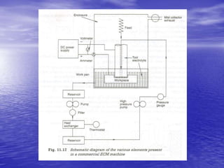
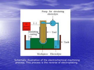


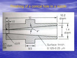
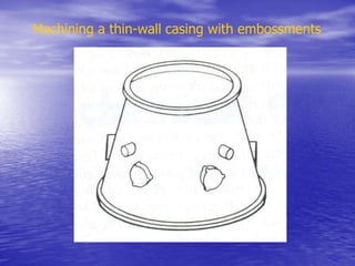
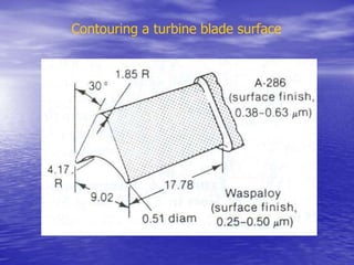
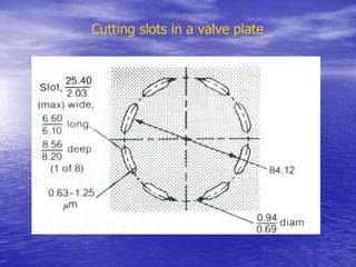

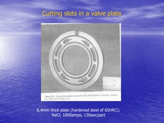
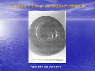
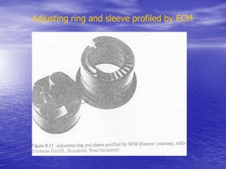
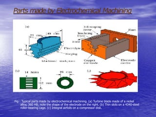
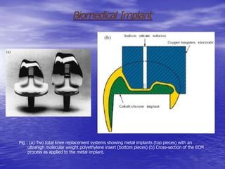

Electrochemical machining (ECM) is a process that removes material from a conductive workpiece using electrical current. In ECM, the workpiece acts as an anode in an electrolyte bath, and material is removed from the workpiece and transported to a cathode tool. ECM can machine complex shapes in a single pass with no cutting forces and leaves the workpiece stress-free. Key factors that affect the ECM process include electrolyte composition and flow, voltage, feed rate, and current density between the tool and workpiece. ECM is used for aerospace, medical, and automotive applications where other machining methods cannot produce the required geometry or precision.