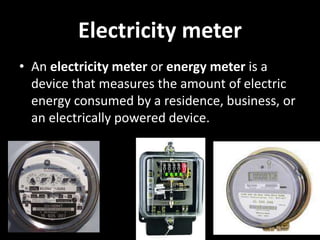
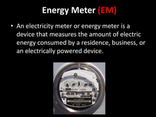
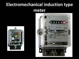
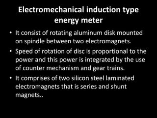
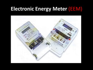
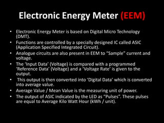
Electric meter
Submitted to: AR. Akriti SUBMITTED BY GAURAV
Electricity meter
• An electricity meter or energy meter is a
device that measures the amount of electric
energy consumed by a residence, business, or
an electrically powered device.
NEED
USE
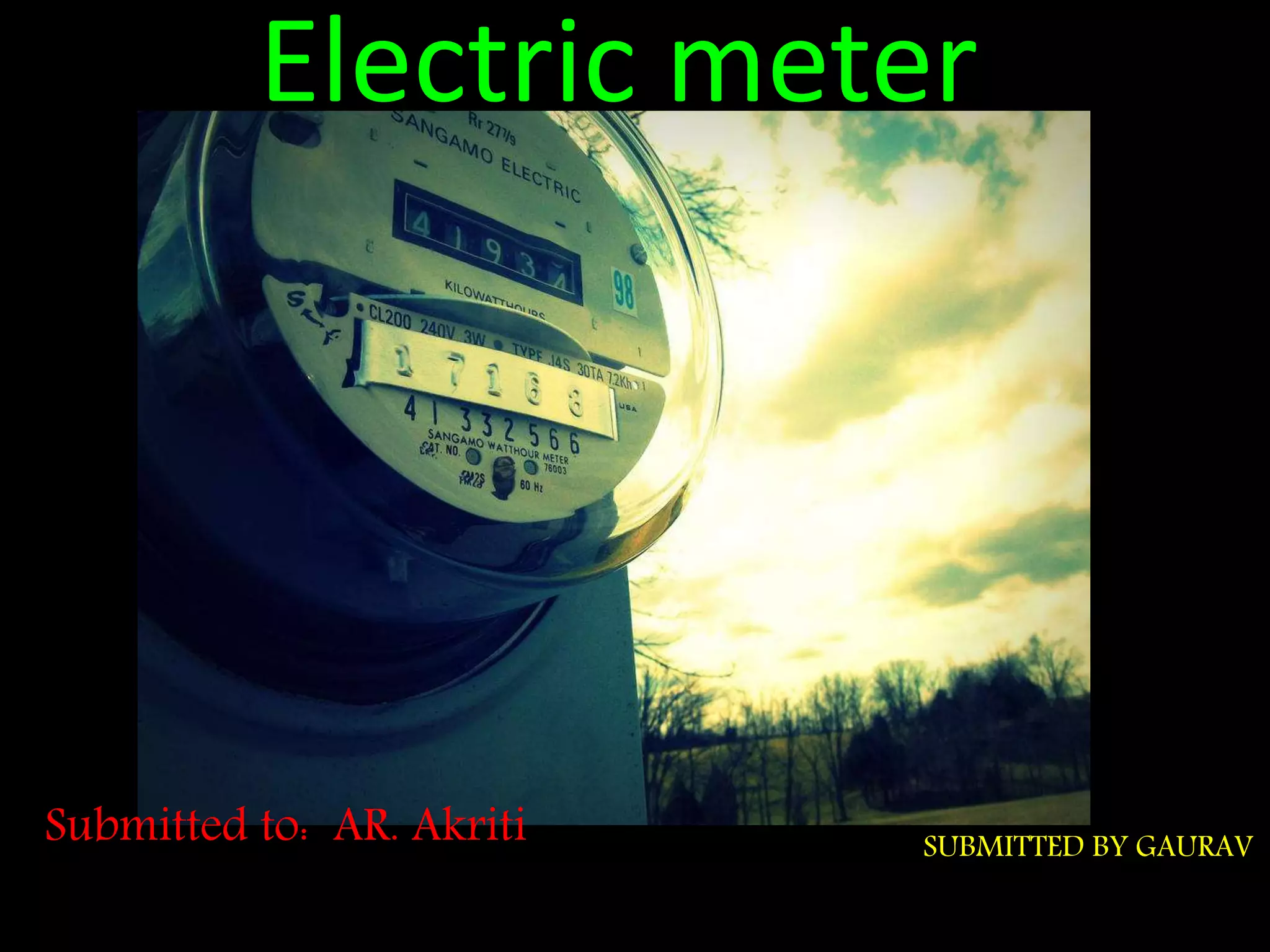
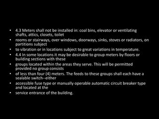
• Electric utilities use electric meters installed at
customers' premises to measure electric energy
delivered to their customers for billing purposes.
They are typically calibrated in billing units, the
most common one being the kilowatt hour
[kWh]. They are usually read once each billing
period.
• The most common unit of measurement on the
electricity meter is the kilowatt hour [kWh]
What Is electrical energy?
• Electrical energy is the product of power (P)
and time (t) of how long the power is
consumed or spend. Unit of measurement is
Kilowatt hour
W= P*t
Kilowatt-hour: The amount of energy consumed by one kilowatt
load over the period of one hour .
Types of Energy Meter(EM)
• There are two types of EM which works on
different mechanism .
• Electromechanical induction type meter
• Electronic meter or solid state meter
Energy Meter (EM)
• An electricity meter or energy meter is a
device that measures the amount of electric
energy consumed by a residence, business, or
an electrically powered device.
How to read electric meter?
• Each of the five dials represent one digit of the
present reading.
• When the hand of one of the dials is between
numbers, always take the smaller number.
Electromechanical induction type
meter
Electromechanical induction type
energy meter
Electromechanical induction type
energy meter
• It consist of rotating aluminum disk mounted
on spindle between two electromagnets.
• Speed of rotation of disc is proportional to the
power and this power is integrated by the use
of counter mechanism and gear trains.
• It comprises of two silicon steel laminated
electromagnets that is series and shunt
magnets..
Connection Diagram
Electronic Energy Meter (EEM)
• Electronic Energy Meter is based on Digital Micro Technology
(DMT).
• Functions are controlled by a specially designed IC called ASIC
(Application Specified Integrated Circuit).
• Analogue circuits are also present in EEM to “Sample” current and
voltage.
• The ‘Input Data’ (Voltage) is compared with a programmed
‘Reference Data’ (Voltage) and a ‘Voltage Rate’ is given to the
output.
• This output is then converted into ‘Digital Data’ which is converted
into average value.
• Average Value / Mean Value is the measuring unit of power.
• The output of ASIC indicated by the LED as “Pulses”. These pulses
are equal to Average Kilo Watt Hour (kWh / unit).
Location of meters ( GENERAL)
• The meter socket shall be plumb, level, and securely
mounted.
• A minimum clearance of three (3) feet shall exist between
the electric metering equipment
• enclosure (considered a source of ignition) and all gas
metering and regulating equipment. The
• 3 foot clearance shall apply in all directions.
• For a single meter position, or a multiple meter position
mounted in a horizontal row
• meter socket shall be five (5) feet above the permanent
ground level, floor or suitable
• platform on which the meter reader will stand when
reading the meter. When multiple meter
• positions are to be mounted in a vertical row,
the meter sockets shall be mounted at a
height
• such that the top of the highest meter socket
or top of the lowest meter socket will not
• exceed 79 inches or be less than 39 inches
respectively, above the permanent ground
level,
• floor, or suitable permanent platform.
Location of meters ( outdoor)
• 3.1 Meters, 6 or less, installed outdoors, should generally be located
directly below the point of
• attachment of the overhead service drop or directly above the
underground service lateral.
• Meters should be located in an area where the meter will not be damaged
and which will remain
• free of obstructions and permit convenient accessibility for meter reading
and testing.
• Additionally, residential electric and gas meters should both be located on
the same side of the
• home within the front 1/3 to aid meter reading, testing and service, and to
aid emergency
• response in the event of a fire or some other hazardous condition.
• 3.2 Meters on underground services shall not be installed on company-
owned poles unless very
• unusual condition exist which make other meter locations impractical. A
meter may be located
• on a Company-owned pole only by written permission of the Local
Operating Area.
INDOOR LOCATION
• 4.1 When meters are installed on the inside of the building, they shall be located
in the cellar or
• basement as near the point of entrance of the entrance run as possible. Where
buildings have
• no cellars, or have damp cellars, or cellars that are not readily accessible, meters
may be
• installed on the first floor near the point of entrance of the entrance run as
possible.
• 4.2 All meters in a building should be grouped in one location in a common
areaway which shall be
• kept unlocked and readily accessible at any time. If no such common areaway is
available,
• written permission shall be obtained from NIPSCO for suitable meter locations.
The location of
• the meters shall be such that one customer's premises being closed would not
make it impossi-
• able to restore service to other customers in the building.
• 4.3 Meters shall not be installed in: coal bins, elevator or ventilating
shafts, attics, closets, toilet
• rooms or stairways, over windows, doorways, sinks, stoves or radiators, on
partitions subject
• to vibration or in locations subject to great variations in temperature.
• 4.4 In some locations it may be desirable to group meters by floors or
building sections with these
• groups located within the areas they serve. This will be permitted
provided no group consists
• of less than four (4) meters. The feeds to these groups shall each have a
sealable switch--either
• accessible fuse type or manually operable automatic circuit breaker type
and located at the
• service entrance of the building.
.

Electricity meter

  • 1.
    Electric meter Submitted to:AR. Akriti SUBMITTED BY GAURAV
  • 2.
    Electricity meter • Anelectricity meter or energy meter is a device that measures the amount of electric energy consumed by a residence, business, or an electrically powered device.
  • 3.
  • 4.
    USE • Electric utilitiesuse electric meters installed at customers' premises to measure electric energy delivered to their customers for billing purposes. They are typically calibrated in billing units, the most common one being the kilowatt hour [kWh]. They are usually read once each billing period. • The most common unit of measurement on the electricity meter is the kilowatt hour [kWh]
  • 5.
    What Is electricalenergy? • Electrical energy is the product of power (P) and time (t) of how long the power is consumed or spend. Unit of measurement is Kilowatt hour W= P*t Kilowatt-hour: The amount of energy consumed by one kilowatt load over the period of one hour .
  • 6.
    Types of EnergyMeter(EM) • There are two types of EM which works on different mechanism . • Electromechanical induction type meter • Electronic meter or solid state meter
  • 7.
    Energy Meter (EM) •An electricity meter or energy meter is a device that measures the amount of electric energy consumed by a residence, business, or an electrically powered device.
  • 8.
    How to readelectric meter? • Each of the five dials represent one digit of the present reading. • When the hand of one of the dials is between numbers, always take the smaller number.
  • 9.
  • 10.
  • 11.
    Electromechanical induction type energymeter • It consist of rotating aluminum disk mounted on spindle between two electromagnets. • Speed of rotation of disc is proportional to the power and this power is integrated by the use of counter mechanism and gear trains. • It comprises of two silicon steel laminated electromagnets that is series and shunt magnets..
  • 12.
  • 13.
  • 14.
    Electronic Energy Meter(EEM) • Electronic Energy Meter is based on Digital Micro Technology (DMT). • Functions are controlled by a specially designed IC called ASIC (Application Specified Integrated Circuit). • Analogue circuits are also present in EEM to “Sample” current and voltage. • The ‘Input Data’ (Voltage) is compared with a programmed ‘Reference Data’ (Voltage) and a ‘Voltage Rate’ is given to the output. • This output is then converted into ‘Digital Data’ which is converted into average value. • Average Value / Mean Value is the measuring unit of power. • The output of ASIC indicated by the LED as “Pulses”. These pulses are equal to Average Kilo Watt Hour (kWh / unit).
  • 15.
    Location of meters( GENERAL) • The meter socket shall be plumb, level, and securely mounted. • A minimum clearance of three (3) feet shall exist between the electric metering equipment • enclosure (considered a source of ignition) and all gas metering and regulating equipment. The • 3 foot clearance shall apply in all directions. • For a single meter position, or a multiple meter position mounted in a horizontal row • meter socket shall be five (5) feet above the permanent ground level, floor or suitable • platform on which the meter reader will stand when reading the meter. When multiple meter
  • 16.
    • positions areto be mounted in a vertical row, the meter sockets shall be mounted at a height • such that the top of the highest meter socket or top of the lowest meter socket will not • exceed 79 inches or be less than 39 inches respectively, above the permanent ground level, • floor, or suitable permanent platform.
  • 17.
    Location of meters( outdoor) • 3.1 Meters, 6 or less, installed outdoors, should generally be located directly below the point of • attachment of the overhead service drop or directly above the underground service lateral. • Meters should be located in an area where the meter will not be damaged and which will remain • free of obstructions and permit convenient accessibility for meter reading and testing. • Additionally, residential electric and gas meters should both be located on the same side of the • home within the front 1/3 to aid meter reading, testing and service, and to aid emergency • response in the event of a fire or some other hazardous condition. • 3.2 Meters on underground services shall not be installed on company- owned poles unless very • unusual condition exist which make other meter locations impractical. A meter may be located • on a Company-owned pole only by written permission of the Local Operating Area.
  • 18.
    INDOOR LOCATION • 4.1When meters are installed on the inside of the building, they shall be located in the cellar or • basement as near the point of entrance of the entrance run as possible. Where buildings have • no cellars, or have damp cellars, or cellars that are not readily accessible, meters may be • installed on the first floor near the point of entrance of the entrance run as possible. • 4.2 All meters in a building should be grouped in one location in a common areaway which shall be • kept unlocked and readily accessible at any time. If no such common areaway is available, • written permission shall be obtained from NIPSCO for suitable meter locations. The location of • the meters shall be such that one customer's premises being closed would not make it impossi- • able to restore service to other customers in the building.
  • 19.
    • 4.3 Metersshall not be installed in: coal bins, elevator or ventilating shafts, attics, closets, toilet • rooms or stairways, over windows, doorways, sinks, stoves or radiators, on partitions subject • to vibration or in locations subject to great variations in temperature. • 4.4 In some locations it may be desirable to group meters by floors or building sections with these • groups located within the areas they serve. This will be permitted provided no group consists • of less than four (4) meters. The feeds to these groups shall each have a sealable switch--either • accessible fuse type or manually operable automatic circuit breaker type and located at the • service entrance of the building.
  • 21.