Download to read offline

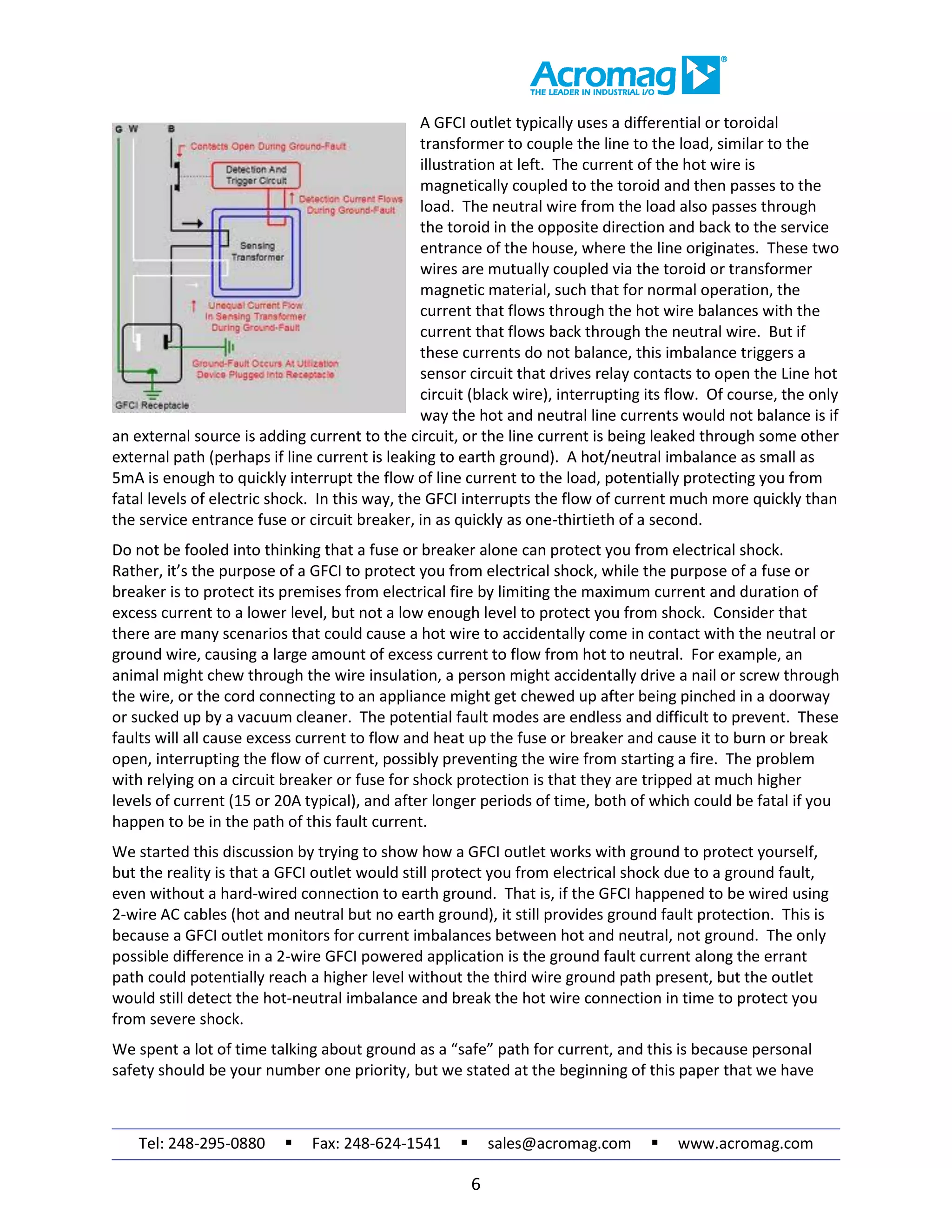

This document is the second part of a three-part series discussing best practices for grounding electrical equipment and the operation of Ground Fault Circuit Interrupter (GFCI) devices which protect users from electrical shock. It explains the importance of grounding for safety and signal integrity, and details how GFCI outlets and breakers work to detect imbalances in current and quickly interrupt electricity flow in the event of a ground fault. The document emphasizes that GFCI devices are crucial for protecting against severe electric shocks while recognizing the limitations of wired grounding systems.


