The document outlines the syllabus and lecture plans for the Electrical Engineering II Year B.Tech I Semester course at Vignan Institute of Technology & Science. It covers five main units, including fundamental electrical concepts, alternating current systems, DC machine operation, AC machine principles, and basic principles of electrical measurement instruments. Each unit includes specific topics, objectives, and quizzes designed to reinforce learning.
![ELECTRICAL ENGINEERING
DEPARTMENT OF ELECTRICAL & ELECTRONICS
ENGINEERING
COURSE MATERIAL
FOR
FOR II/IV B.Tech I Semester
[Common to Mech.Engg – Mechatronics and Mech.Engg – Production]
Dr. NARASIMHAM R.L.
VIGNAN INSTITUTE OF TECHNOLOGY & SCIENCE
VIGNAN HILLS, DESHMUKHI VILLAGE,
POCHAMPALLY (MANDAL)
NALGONDA (Dt.) – 508 284](https://image.slidesharecdn.com/coursefileelectricalengineering-240517161717-1b4e3c5f/85/Electrical-Electronics-engineering-document-1-320.jpg)
![ELECTRICAL ENGINEERING
DEPARTMENT OF ELECTRICAL & ELECTRONICS
ENGINEERING
COURSE MATERIAL
FOR
FOR II/IV B.Tech I Semester
[Common to Mech.Engg – Mechatronics and Mech.Engg – Production]
Dr. NARASIMHAM R.L.
VIGNAN INSTITUTE OF TECHNOLOGY & SCIENCE
VIGNAN HILLS, DESHMUKHI VILLAGE,
POCHAMPALLY (MANDAL)
NALGONDA (Dt.) – 508 284](https://image.slidesharecdn.com/coursefileelectricalengineering-240517161717-1b4e3c5f/75/Electrical-Electronics-engineering-document-1-2048.jpg)
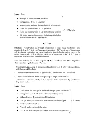
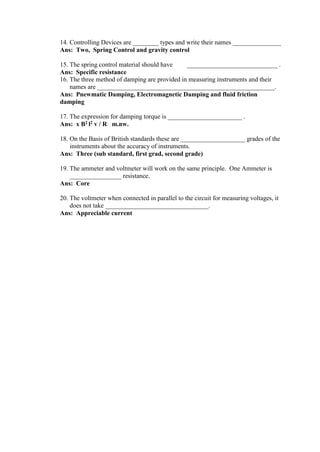
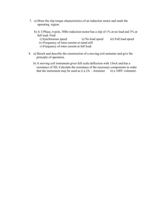
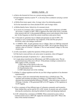
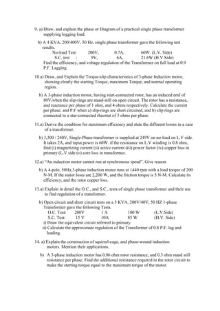
![UNIT – I QUIZ – I
1) The Basic electric quantities are
a) Charge & voltage b) Energy & Current
c) Charge & Energy d) Voltage & Current [ ]
2) Current is defined as
a) Rate of change of charge b) Product of charge & time
c) Rate of charge of flux d) Rate f charge of voltage [ ]
3) The difference of Potential between two points in a circuits
a) Voltage b) Current
c) Resistance d) Zero [ ]
4) A circuit element draws a constant current of 5A at a constant voltage of 10v. The
energy absorbed by it in one hour
a) 50 kwh b) 15kwh c) 0.5kwh d) 0.05kwh [ ]
5) The circuit element absorbs 500 watts of power with a current of 10A, its voltage is
a) 500v b) 450v c) 50v d) 510v [ ]
6) The voltage and current across a resistor are 5v, 2A respectively, The value of the
resistance and the power absorbed are
a) 2.5 & 10Watts b) 5 & 5W
c) 0.5 & 10W d) 2.5 & 5W [ ]
7) The resistance of wire is directly proportional to
a) The area of cross section b) 1(1 = length of wire)
c) Both a & b d) The current passing through it [ ]
8) A cell emf 1.45 volts and internal resistance 4 is connected to a resistance of 1,
what current will flow
a) 2.9A b) .29A c) 29A d) 0.029A [ ]
9) The total power in a series circuit is 10 watts. There are five equal value resistors in
the circuit. How much power does each resistance dissipate
a) 10 w b) 5 w c) 2 w d) 1 w [ ]
10) An electric iron takes 2.5A at 250v, what is its hot resistance
a) 100 b) 9.2 c) 29 d) 92 [ ]
11) The basic unit of charge is the charge of an _________ But this charge is very small.
12) The energy spent at unit charge in transporting it from one terminal to the other is
called the _____________________](https://image.slidesharecdn.com/coursefileelectricalengineering-240517161717-1b4e3c5f/85/Electrical-Electronics-engineering-document-6-320.jpg)
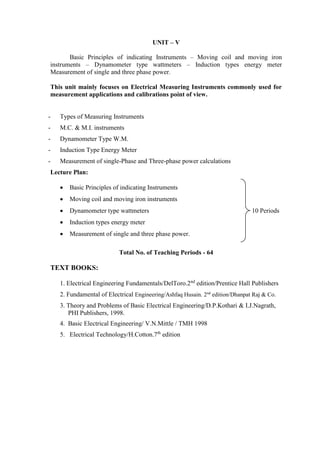
![UNIT – II QUIZ – II
1) For a constant currents an inductor acts as
a) Open circuit b) short circuit
c) a current source d) a finite resistance [ ]
2) For a constant voltage, a capacitor acts as
a) Open circuit b) a short circuit
c) a current source d) a finite resistance [ ]
3) What is the source in energy of hydro-electric stations
a) Steam b) coal c) oil d) water [ ]
4) The current though an inductor
a) can change suddenly b) can not change suddenly
c) is zero d) is infinite [ ]
5) The voltage across an inductor
a) can change suddenly b) can not change suddenly
c) is zero d) is infinite [ ]
6) The energy stored in an inductor is
a) ½ LI2
t b) ½ LI2
c) ½ L2
I d) LI2
[ ]
7) The energy stored in capacitor is
a) Zero b) ½ CV2
c) ½ CI2
d) CV2
[ ]
8) A capacitor is defined by
a) Q = CV b) I = cvdt c) V = L (di/dt) d) Q = CI [ ]
9) An inductor is defined by
a) I = L(dv/dt) b) I = L vdt c) V = L(di/dt) d) V = Li dt [ ]
10) The internal resistance of an ideal voltage source
a) finite b) infinite c) unknown d) Zero [ ]
11) The internal resistance of an ideal current source
a) finite b) infinite c) unknown d) Zero [ ]
12) Which of the following is correct
a) q = di/dt b) I = dq/dt c) I = q dt d) none [ ]](https://image.slidesharecdn.com/coursefileelectricalengineering-240517161717-1b4e3c5f/85/Electrical-Electronics-engineering-document-8-320.jpg)
![13) Which of the following is correct
a) Energy = (Power)dt b) Power = Energy/time
c) power d/dt (Energy) d) all the above [ ]
14) The total inductance of the coils 1 & 2 connected in series as their fluxes is additive
a) L1 + L2 – M b) L1 + L2 – 2M
c) L1 + L2 + M d) L1 + L2 + 2M [ ]
15) Which of the following is correct for a coil
a) L = N d/dt b) L = N d/dI
c) L = N dI/dt d) all the above [ ]
16) There are two sine wave V1 = Vm Sin(wt) and V2 = Vm Sin(wt + /4) then
a) V1 leads V2 by 45 b) V2 leads V1 by 45
c) V1 & V2 are in phase d) V2 lags behind V1 by 45 [ ]
17) The peak value of the sine wave I = 100 Sint is
a) 100 b) 100/2 c) 50 d) –100 [ ]
18) The magnitude of the impulse function d(t) is
a) infinity b) unity c) indetermine d) Zero [ ]
19) What is the phase angle between the induction current and the applied voltage in a
Parallel RL circuit is
a) 0 b) 45 c) 90 d) 180 [ ]
20) What is the phase angle between the capacitor current and applied voltage
a) 0 b) 45 c) 90 d) 180 [ ]
21) In a certain parallel RL circuit R = 50 & XL = 75 what is the admittance
a) 0.024s b) 75s c) 50s d) 1.5s [ ]
22) A series R – L circuit has a resistance of 50 k. What its impedance and phase angle
a) 56.58, 59.9 b) 59.9k
c) 59.9,56.58 d) 5.99, 56.58 [ ]
23) In a given RLC circuit R = 0, Xc is 150 and XL is 80 what is its total impedance?
What is the type of reactance
a) 70, inductive b) 70, capacitive
c) 70, resistive d) 150, capacitive [ ]](https://image.slidesharecdn.com/coursefileelectricalengineering-240517161717-1b4e3c5f/85/Electrical-Electronics-engineering-document-9-320.jpg)
![24) Apparent power is expressed in
a) Volt – amperes b) apparent power
c) watts d) VAR [ ]
25) A power factor of 1 indicates
a) purely resistive circuit b) Purely reactive circuit
c) combination of both a & b d) none [ ]
26) For a certain load, the true power is 100w and the reactive power is 100VAR. what is
the apparent power
a) 200 VA b) 100 VA c) 141.4 VA d) 120 VA [ ]
27) If the phase angle is 45, what is the power factor
a) Cos 45 b) Sin 45 c) tan 45 d) none [ ]
28) What is the phase angle at resonance in a series RLC circuit
a) 0 b) 90 c) 45 d) 30 [ ]
29) What is the total impedance of a series RLC circuit at resonance
a) equal to XL b) equal to XC c) equal to R d) Zero [ ]
30) What is the impedance of an ideal parallel resonant circuit without resistance in
either branch
a) zero b) Inductive c) capacitive d) infinitive [ ]
31) In a series RLC circuit operating below the resonant frequency, the current
a) I leads Vs b) I lags behind Vs
c) Irs in phase with Vs d) Vs lags by I [ ]
32) The peak value of a sine wave Y = 400 Sin t is
a) 400 b) 400 / 2 c) 200 d) – 400 [ ]
33) The rms value of a Sine wave Y = 400 Sint is
a) 400 b) 400 / 2 c) 200 d) – 400 [ ]
34) The Q- factor of a circuit can be increased by
a) increasing BW b) decreasing BW
c) increasing R d) none [ ]](https://image.slidesharecdn.com/coursefileelectricalengineering-240517161717-1b4e3c5f/85/Electrical-Electronics-engineering-document-10-320.jpg)
![35) At certain frequency, IL becomes equal to IC and then IT becomes zero. This
condition is known as
a) series resonance b) parallel resonance
c) Both a & b d) none [ ]
36) In series circuit of L = 15MH, C=0.015F and R = 80 what is the impedance at the
resonant frequency
a) (15mH)w b) (0.015F)w c) 80 d) 0.015 / w [ ]
37) What is the impedance of an ideal parallel resonant circuit without resistive in either
branch
a) zero b) inductive c) infinitive d) capacitive [ ]
38) The lowest cut – off frequency is 2400Hz and the upper cut – off frequency is 2800 Hz
what is the Band width
a) 2800Hz b) 2400Hz c) 400Hz d) 5200Hz [ ]
39) The rms voltage measured across on admittance (u + jB) is V. the reactive power for
the element is
a) V2
B b) – V2
B c) V2
(u2
+ b2
)1/2
d) V2
(A + jB) [ ]
40) The power factor of the circuit is equal to the
a) Cosine of the phase angle b) Tangent of the phase angle
c) Sine of the phase angle d) Unity for reactive circuit [ ]
41) The average value of a sine wave is
a) 1 b) (Peak value) / 2 c) (Peak value) X 2 d) zero [ ]
42) The peak factor is defined as
a) VPeak / V rms b) VPeak / Vavg
c) VPeak / Time period d) none [ ]
43) Form factor is the relation between
a) Instantaneous & average values of a signal
b) RMS & average values of signal
c) Apparent value & average of a signal
d) DC value of signal [ ]
44) What is the other name of RMS value
a) form factor b) effective value
c) Maximum value d) Average value [ ]](https://image.slidesharecdn.com/coursefileelectricalengineering-240517161717-1b4e3c5f/85/Electrical-Electronics-engineering-document-11-320.jpg)
![45) The ratio of true power to apparent power is
a) Energy b) Power factor c) error d) Peak factor [ ]
46) In a purely resistive load, the true power is 5 watts and its apparent power is_______
47) If 1/ 2 is the power factor then phase angle is ____________________
48) EMF equation may be written e = Em Sint where e is _________________
49) The product of VI called ___________________ and is measured in__________
50) The ratio of active power to apparent power is _____________________](https://image.slidesharecdn.com/coursefileelectricalengineering-240517161717-1b4e3c5f/85/Electrical-Electronics-engineering-document-12-320.jpg)


![UNIT-I Final (1)[1].pptfgcvhvjgbjhbjgbjhhvhvhvh](https://cdn.slidesharecdn.com/ss_thumbnails/unit-ifinal11-251129122433-e786871d-thumbnail.jpg?width=640&height=640&fit=bounds)


