This document provides details of the modified course curriculum for the 4th semester BTech program in Electrical Engineering. It includes 10 courses with a total credit of 28. Some of the key courses include Electrical Machines-I, Power Systems I, Digital Electronics, Circuit Theory, and Microprocessors & Microcontrollers. For each course, the document provides information on course code, credit hours, prerequisites, topics to be covered, reference books, and course outcomes. It also provides the course structure for the Electrical Machines-I course including detailed topics in each part.
International Journal of Engineering Research and Applications (IJERA) is an open access online peer reviewed international journal that publishes research and review articles in the fields of Computer Science, Neural Networks, Electrical Engineering, Software Engineering, Information Technology, Mechanical Engineering, Chemical Engineering, Plastic Engineering, Food Technology, Textile Engineering, Nano Technology & science, Power Electronics, Electronics & Communication Engineering, Computational mathematics, Image processing, Civil Engineering, Structural Engineering, Environmental Engineering, VLSI Testing & Low Power VLSI Design etc.
Analysis of 1MHz Class-E Power Amplifier for Load and Duty Cycle VariationsIJPEDS-IAES
This paper presents the simulation and experimental of Class-E power
amplifier which consists of a load network and a single transistor. The
transistor is operated as a switch at the carrier frequency of the output signal.
In general, Class-E power amplifier is often used in designing a high
frequency ac power source because of its ability to satisfy the zero voltage
switching (ZVS) conditions efficiently even when working at high
frequencies with significant reduction in switching losses. In this paper, a
10W Class-E power amplifier is designed, constructed, and tested in the
laboratory. SK40C microcontroller board with PIC16F877A is used to
generate a pulse width modulation (PWM) switching signal to drive the
IRF510 MOSFET. To be specific, in this paper, the effect on switching and
performance at 1MHz frequency are studied in order to understand the Class-
E power amplifier behavior. Performance parameters relationships were
observed and analysed in respect to the load and duty cycle. The proposed
Class-E power amplifier efficiency is 98.44% powered with 12V dc,
operated at frequency 1MHz and 50% duty cycle to produce a stable
sinusoidal signal. Theoretical calculations, simulation and experimental
results for optimum operation using selected component values are then
compared and presented.
Application of Distribution Power Electronic Transformer for Medium VoltageIAES-IJPEDS
In this paper a distribution power electronic transformer (DPET) for feeding critical loads is presented. The PE based transformer is a multi-port converter that can connect to medium voltage levels on the primary side. Bidirectional power flow is provided to the each module. The presented structure consists of three stages: an input stage, an isolation stage, and an output stage. The input current is sinusoidal, and it converts the high AC input voltage to low DC voltages. The isolated DC/DC converters are then connected to the DC links and provide galvanic isolation between the HV and LV sides. Finally, a three-phase inverter generates the AC output with the desired amplitude and frequency. The proposed DPET is extremely modular and can be extended for different voltage and power levels. It performs typical functions and has advantages such as power factor correction, elimination of voltage sag and swell, and reduction of voltage flicker in load side. Also in comparison to conventional transformers, it has lower weight, lower volume and eliminates necessity for toxic dielectric coolants the DPET performance is verified in MATLAB simulation.
International Journal of Computational Engineering Research (IJCER) ijceronline
International Journal of Computational Engineering Research(IJCER) is an intentional online Journal in English monthly publishing journal. This Journal publish original research work that contributes significantly to further the scientific knowledge in engineering and Technology
Single-Phase Multilevel Inverter with Simpler Basic Unit Cells for Photovolta...IAES-IJPEDS
This paper presents a single-phase multilevel inverter (MLI) with simpler
basic unit cells. The proposed MLI is able to operate in two modes, i.e.
charge mode to charge the batteries, and inverter mode to supply AC power
to load, and therefore, it is inherently suitable for photovoltaic (PV) power
generation applications. The proposed MLI requires lower number of power
MOSFETs and gate driver units, which will translate into higher cost saving
and better system reliability. The power MOSFETs in the basic unit cells
and H-bridge module are switched at near fundamental frequency, i.e. 100
Hz and 50 Hz, respectively, resulting in lower switching losses. For low total
harmonic distortion (THD) operation, a deep scanning method is employed
to calculate the switching angles of the MLI. The lowest THD obtained is
8.91% at modulation index of 0.82. The performance of the proposed MLI
(9-level) has been simulated and evaluated experimentally. The simulation
and experimental results are in good agreement and this confirms that the
proposed MLI is able to produce an AC output voltage with low THD.
INTRODUCTION BASIC TECHNIQUES TYPE OF BUSES
Y BUS MATRIX POWER SYSTEM COMPONENTS BUS ADMITTANCE MATRIX
Power (Load) flow study is the analysis of a power system in normal steady-state operation
This study will determine:
IMPEDANCE SOURCE INVERTER TOPOLOGIES FOR PHOTOVOLTAIC APPLICATIONS – A REVIEWIAEME Publication
The impedance source inverters can step up the voltage and hence, they are greatly preferred for photovoltaic applications. There are many impedance and quasi impedance network topologies available. The key factor in selection of topology is the amount of voltage gain obtained along with the reduced number components. This paper compares some of the impedance and quasi - impedance source inverter (qZSI) topologies for photovoltaic applications namely, switched coupled inductor qZSI, switched ZSI, enhanced-boost quasi ZSI with continuous and discontinuous source current topologies, enhanced -boost active qZSI, switched-boost ZSI and high gain switched boost inverter. The parameters taken for comparison are voltage gain, boost factor, voltage, and current stresses on the components etc. Based on the comparison, the high gain switched boost ZSI is found to have high voltage gain along with reduced voltage and current stress. The review will be useful for researchers working in impedance source inverter network.
PARTICLE INITIATED FOV OF HYBRID CYLINDRICAL INSULATING SPACERS UNDER AC AND ...IAEME Publication
The ever – increasing voltage levels in electrical power systems need to enhance the power distribution and transmission system. The insulation failure is mainly due to the high voltage stress. The dielectric strength of air is greatly influenced by the presence of insulating surfaces. In the present research work the new hybrid cylindrical insulating spacers such as PMMA – PP, PP – NYLON and NYLON – PMMA and the orientation of hybrid cylindrical insulating spacers has been studied. The flashover performances are carried out experimentally in air as insulating media for different electrode configuration such as uniform electric field (Plane – Plane), non-uniform electric field (Needle – Plane) and moderately non-uniform electric field (Hemisphere rod – Plane) under AC and DC voltages. The effect of conducting floating particles is also carried out for different electrode configuration under AC and DC voltages. The experimental investigations shows that NYLON – PP and NYLON – PMMA hybrid spacers has highest flashover voltage (FOV) under AC voltages, in case of DC voltages PP – NYLON hybrid spacer gives highest FOV. The hybrid spacer PP – NYLON has more effective under AC voltage, whereas in case of DC voltage PMMA – NYLON has more effective with conducting floating particles.
Power System Simulation Laboratory Manual Santhosh Kumar
Date:-(13-07-2016)
Hii friends
I Have Attached Our Power System Simulation Laboratory Manual Here for your Reference
Kindly download the Manual and Start Writing the Observation Note By Mr.G.Shivaraj-AP/EEE
Please follow it friends✌
With Happy,
Šαηтн๑zzζzz
Design an electric vehicle using PV array with five phase permanent magnet sy...ijtsrd
The purpose of this project is to design an Electrical vehicle with help renewable energy source which can carry the lab equipment, books and other goods from one building to other building of AL FALAH UNIVERSITY also student as well as professors can go easily from one building to other building of AL FALAH UNIVERSITY. This paper gives a review of the electric vehicle technology that focuses on the types of drives and the control of speed of five phase permanent magnet synchronous motor. This paper highlights the characteristics, performance measure, requirements and the operational procedure of the electric vehicle drives and control. Dhirender Kumar | Ameen Uddin Ahmad "Design an electric vehicle using PV array with five-phase permanent magnet synchronous motor." Published in International Journal of Trend in Scientific Research and Development (ijtsrd), ISSN: 2456-6470, Volume-3 | Issue-6 , October 2019, URL: https://www.ijtsrd.com/papers/ijtsrd29173.pdf Paper URL: https://www.ijtsrd.com/engineering/electrical-engineering/29173/design-an-electric-vehicle-using-pv-array-with-five-phase-permanent-magnet-synchronous-motor/dhirender-kumar
Basic MOSFET Based vs Couple-Coils Boost Converters for Photovoltaic GeneratorsIJPEDS-IAES
Considering the optimization of a photovoltaic system, several studies show the advantage in the choice of a distributed structure. For such structures small power converters such as the boosts and buck converters appear as most appropriate. We have analysed the efficiency of small power boost- converters especially dedicated for photovoltaic energy conversion systems working in the middle and high voltage ranges. The setup studied is a photovoltaic generator connected to an AC grid working in 230 Volts via an inverter. Moreover, we considered the possibility of multiple electrical energy sources as photovoltaic, wind systems in the same energy production system, which obliged an adaptive converter structure. We evaluated the losses in the various stages of a boost converter and point out the importance of the power MOSFET used as the commutation element. New transistors databases obtained from manufacturers show the nonlinear dependency between the resistance drain-source when passing, Rdson and the maximum rating voltage when the transistor is off, Vdsmax, for all transistor families. Thus nonlinear dependency induces a huge increase of losses with the voltage in the MOSFET, and as a direct consequence in the converter the more as Vdsmax is higher. In order to minimize losses of the converter we have designed and realized a new high efficiency version of a Step-Up structure based on a commutation element integrating a low Vdsmax voltage MOSFET and very low Rdson.
Maximum Power Point Tracking Method for Single Phase Grid Connected PV System...Ali Mahmood
Ordinary technique fail to ensure successful tracking of the maximum power point under partial shading conditions (PSC). This performs in significant reduction in the power generated as well as the reliability of the photovoltaic energy production system. For the effective utilization of solar panel under partial shading condition (PSC), maximum power point tracking method (MPPT) is required.
This comprehensive program covers essential aspects of performance marketing, growth strategies, and tactics, such as search engine optimization (SEO), pay-per-click (PPC) advertising, content marketing, social media marketing, and more
NIDM (National Institute Of Digital Marketing) Bangalore Is One Of The Leading & best Digital Marketing Institute In Bangalore, India And We Have Brand Value For The Quality Of Education Which We Provide.
www.nidmindia.com
Exploring Career Paths in Cybersecurity for Technical CommunicatorsBen Woelk, CISSP, CPTC
Brief overview of career options in cybersecurity for technical communicators. Includes discussion of my career path, certification options, NICE and NIST resources.
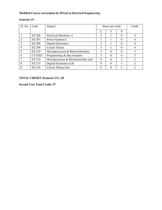
1. Modified Course curriculum for BTech in Electrical Engineering
Semester IV
Sl. No. Code Subject Hours per week Credit
L T P
1 EE 206 Electrical Machines -I 3 1 0 4
2 EE 207 Power Systems I 3 1 0 4
3 EE 208 Digital Electronics 3 1 0 4
4 EE 209 Circuit Theory 3 1 0 4
5 EE 210 Microprocessors & Microcontrollers 3 0 0 3
6 CS XXX Programming & data structure 3 0 0 3
7 EE 214 Microprocessor & Microcontroller Lab 0 0 3 2
8 EE 215 Digital Electronics Lab 0 0 3 2
9 EE 216 Circuit Theory Lab 0 0 3 2
TOTAL CREDIT (Semester IV): 28
Second Year Total Credit: 57
2. EE 206 Electrical Machines-I L T P C
4th Semester 3 1 0 4
Electrical Engineering Branch
Pre-requisites: Basic Electrical Engineering, Circuit theory
Part-I:
1. Constructional features: Magnetic circuit: Different types of field and armature structures, their
placement and magnetic path with special reference to transformer. Material used, laminations, magnetic
saturation. Arrangements in Transformer, DCM, SM, IM
2. Electric circuit: Different types of field and armature windings, pole formation, and winding parameters
(full pitch & short pitch) concentrated winding and distributed winding, single layer and double layer
winding). Brush slip ring &commutator arrangement. Arrangements in Tr., DCM, IM, SM.
3. Insulation system: material used, class of insulation.
4. Cooling circuit: Cooling arrangement, medium used for cooling.
5. Magneto-motive force: Nature of MMF developed by concentrated winding carrying DC and AC, their
Fourier series components, Nature of mmf due to distributed winding, harmonic reduction, Flux density
distribution as a function of path reluctance, main flux and leakage flux, Equation for the instantaneous
value of flux linked by a concentrated coil, Nature of MMF produced in Tr., DC, IM
6. Electromotive Force: Expressions of induced emfs developed across a concentrated coil due to relative
motion between flux and coil, due to flux pulsation and that due to both relative motion and flux pulsation.
The rotation of a concentrated coil in different types of flux density. Modified expression for emf developed
across distributed winding. Nature of the emf developed across the coil in Transformer, DC m/c, induction
m/c and synchronous m/c. Lump parameter equivalent circuit models for DC m/c, IM and SM, Transformer,
Field energy and derivation of generalized torque equation, Energy flow and efficiency, rating and name
plate data.
Part-II:
1. DC Generators: EMF equation, Classification on methods of excitation, armature reaction, interpoles
and compensating winding, commutation, load characteristic of DC generators, voltage regulation, parallel
operation.
2. DC Motors: Torque equation, characteristic curves of shunt, series and compound motors, starter and
grading of starting resistance, speed control – armature voltage control and field control methods. Ward
Leonard method, speed regulation, losses and efficiency, testing- Swinburn’s test, back to back test, brake
test.
3. Transformer: Emf equation, relation between voltage per turn and KVA output, phasor diagram based
on approx. and exact equivalent circuit, per unit equivalent resistance and reactance, open circuit and short
circuit tests, back to back test, voltage regulation, losses and efficiency, maximum efficiency, All day
efficiency, Two winding and three winding transformers, auto transformer, phase transformer and
connections, parallel operation.
3. 4. Polyphase Induction Motor: Principle of operation of poly phase induction motors, equivalent circuit
and phasor diagram, locus diagrams, torque and power, speed – torque curve – effect of rotor resistance,
deep bar and double cage rotors, performance calculation from circle diagram, methods of speed control,
testing, losses and efficiency, application, induction generators and induction regulator.
Reference Books:
S. N. Name of Books Authors Publishers
1. Electrical Machines P.S. Bimbhra Khanna Publishers
2. Electrical Machines Nagrath& Kothari TMH
3. Electrical Machines Dr. S.K. Sen Khanna Publishers
Course Outcomes: At the end of this course, students are able to:
CO1: Understand the fundamental principles and classification of electrical machines
CO2: Describe the constructional details, principle of operation of DC machines, Transformers, Induction
Motors
CO3: Develop the steady state equivalent circuit model and analyse the performance through testing for
DC machines, Transformers, Induction Motors
CO4: Choose different types of rotating machines and transformers suitable for different applications
EE 207 Power Systems-I L T P C
4th Semester 3 1 0 4
Electrical Engineering Branch
Prerequisites: Basic Electrical Engineering, Circuits and Networks, Electromagnetic Field Theory
Introduction to various Power Plants: Introduction to conventional sources and non-conventional
sources of energy; their scopes for energy conversion. Overview of different Conventional and Non
Conventional Power Generation Plants. . [4 Hours]
2. Economics of Power Systems: Definitions of Load, connected load, Base load , Peak load, Demand,
Demand intervals, Demand factor, Average load, Load factor, Diversity factors, Utilization factor, Capacity
factor and Load curve. Problems
Economics of power factor improvement, Tariff structures, Problems [5 Hours]
3. Transmission Systems: Introduction; Transmission voltages; Classification of Transmission System,
Advantages of High voltage transmission; comparison of Overhead and underground supply system;
Comparison of AC and DC transmission system; Economic choice of conductor size, Kelvin's law. Per unit
values for steady state condition, Single line diagram. [7 Hours]
4. Overhead Transmission Line and its Parameters: Introduction; Resistance: Resistance of Overhead
line, Calculations of resistance;
Inductance: Inductance of solid cylindrical conductor, composite conductors, two conductor single phase
line, three phase single circuit and double circuit lines with symmetrical and unsymmetrical spacing,
transposed and un transposed line.
Capacitance: Capacitance of two wire line, three phase symmetrical and unsymmetrical line, Charging
current, Effect of earth on capacitance of transmission line.
Skin and proximity Effects.
4. Corona: Critical Disruptive and Visual Disruptive voltages, Factors effecting corona, Corona power loss;
advantages and disadvantages of corona. [10 Hours]
5. Insulators and Underground Cables: Insulators and its types; Voltage grading of Insulators; string
efficiency, Methods of improving string efficiency, Grading; Sag: Calculation of sag, ice and wind loading,
Stringing chart.
Cables: Construction three core cables; Capacitance of three core cables; Most economical size of
conductor; Grading of cables: Types of grading; Breakdown voltages. [6 Hours]
6. Distribution Systems (DS): Introduction; Classification of DS; Feeders, distributors, service mains of a
typical DS; Primary AC DS - Radial feeders, Parallel feeders, Loop feeders and Interconnected network
system; Secondary AC DS - Three phase four wire system and Single phase two wire DS; Methods of
calculation of AC DS; Current loading and voltage drop diagram.
[8 Hours]
Reference Books:
S. N. Author Name of Book Publisher
1. C.L. Wadhwa Electrical Power systems Wiley Eastern
2. AshfaqHussain Electrical Power System CBS Publishers
3. B.R.Gupta Generation of Electrical Energy S. Chand.
4. Soni, Gupta,Bhatnagar Electric Power DhanpatRai& Sons
5. J.B.Gupta A course in Power Systems S. K. Katia & Sons
6. O.I.Elgerd Electric Energy system Theory – An Introduction Tata
McgrawHilll
Course Outcomes:
At the end of the course, students will be able to
1. Explain the working principle of various power generation plants.
2. Define important economical indices for designing power plants.
3. Design and state the importance of various power apparatuses used in transmission and distribution
systems
4. Compute and analyze essential electrical parameters for over head and underground power lines.
Course Articulation Matrix (CO-PO Mapping):
PO1 PO2 PO3 PO4 PO5 PO6 PO7 PO8 PO9 PO10 PO11 PO12
CO1 3
CO2 3 2 2
CO3 3 3 1
CO4 3 2 2
EE 208 Digital Electronics L T P C
4th Semester 3 1 0 4
Electrical Engineering Branch
Prerequisite: Analog Electronics (EE 202)
5. 1. Logic Families and Logic Gates: TTL, ECL, NMOS, CMOS and PTL logic families and realization
of basic logic gates-AND, OR, NOT, NAND, NOR, XOR, XNOR. Transfer characteristics, Inverter
ratios, Noise margin, power consumption, propagation delays, fan-in and fan-out.
2. Number Systems and Codes: Signed and unsigned numbers and their arithmetic operation, Binary,
Hexadecimal, Octal numbers and their conversions. BCD, Excess-3, Gray, 3 out of 5 and Alpha-
numeric codes, Boolean Algebra.
3. Combinational Logic Circuits: Two-level and Multi-level logics, single and Multi-output
functions, logic minimization, K-Map and Queen-Mclauski’s Method, Multiplexers, Demultiplexers,
Encoder, Decoder, Priority Encoder, parity checkers, half-adders and Full adders
4. Sequential Logic Circuits: Latches and Flip-flops: RS, JK, D-type Flip-flops, Master-slave flip-
flops, Edge triggered FF. Shift Registers- serial and parallel and mixed modes, Counters-Binary,
Ripple, Synchronous, asynchronous, Mod-K and decade counters and their design.
5. Introduction to ADCs: flash ADC, dual slope ADC, successive approximation ADC, DAC, R-2R
ladder network, weighted resistance DAC, Weighted capacitance DAC.
6. Semiconductor Memories: ROM, PROM, EPROM, Static and Dynamic RAM, MOS memories,
Flash Memory, Memory addressing.
Reference Books:
S. N. Author Name of Book Publisher
1. Malvino and Leech Digital Principles and Application McGraw-Hill
2. M .M. Mano Digital logic and Computer Design 3rd Edition, Prentice Hall
3. Alan Markovitz Introduction to Logic Design McGraw-Hill
4. R.P. Jain Modern Digital Electronics
4th
Edition, Tata-McGraw
Hill
5. J.M. Rabaey
Digital Integrated Circuits: A
Design Perspective
2nd Edition, Prentice Hall
6. Zvi Kohavi
Switching and Finite Automata
Theory
Tata-McGraw Hill
COs
After successful completion of the course, students should be able to
1. Understand the fundamental concepts and techniques used in digital electronics.
2. Understand and examine the structure of various number systems, logic families, logic gates and
their application in digital design.
3. Analyze and design various combinational and sequential circuits.
4. Explain the analog to digital and digital to analog converters
5. Classify and design semiconductor memories
1 2 3 4 5 6 7 8 9 10 11 12 PSO1 PSO2 PSO3
6. CO
1 3 3 - - - - - - - - - 1 3 2 -
2 3 3 - - - - - - - - - 1 3 2 -
3 3 3 2 - 2 - - - - - - 1 3 2 -
4 3 3 - 2 - - - - - - 1 3 2 -
5 3 3 - - - - - - - - - 1 3 2 -
EE 209 Circuit Theory L T P C
4th Semester 3 1 0 4
Electrical Engineering Branch
Prerequisite: Basic Electrical Engg, and Mathematics I & Mathematics II
Course Assessment methods (both continuous and semester end assessment): It may be class tests,
assignments, attendance, quiz, poster/seminar presentation on different topics including contemporary
issues, mid Semester examination, surprise tests, coding and simulation, self-learning, grand viva, group
discussion, end semester examination, etc.
Topics Covered:
1. Revision of Networks Theorems (for AC circuits): Maximum Power Transfer Theorem,
Millman’s Theorem, Reciprocity Theorem, Substitution Theorem, Compensation Theorem,
Tellegen’s Theorem.
2. Two Port Networks: One port and two port networks, Sign convention, Admittance Parameters,
Impedance Parameters, Hybrid Parameters, Inverse Hybrid Parameters, Serial and Parallel
connection of two port networks. Driving point and transfer admittance and impedance.
Symmetrical two ports and bisection, Image impedance. Conversion of impedances from star to
delta and vice-versa using two port circuit analyses.
3. Magnetically Coupled Circuit (MCC): Mutual Inductance, Coupling coefficient, Dot convention
for MCC, Energy stored in MCC, Analysis of MCC, T-equivalent network of a transformer.
4. Graph Theory: Definition of node, branch, loop and mesh, Graph of a network, Tree, Co-tree,
Incidence matrix, cut-set matrix, tie-set matrix and loop currents, Number of possible trees of a
graph, Analysis of Networks, Network Equilibrium Equation, Duality.
5. Applications of Laplace Transform: Familiarization with standard electrical signals, Waveform
Synthesis, Theorems and properties of Laplace Transform- Initial and Final Value theorems,
Circuit response to arbitrary inputs using Laplace Transform.
6. Frequency Response: Concept of complex frequency, complex frequency plane, pole and zero,
plot of poles and zeros of simple RL, RC and RLC circuit connected in series and parallel, Polar
7. plot. Concept of resonance – series and parallel resonance, Q-factor, half power frequencies,
concept of transfer function of a network.
7. Fourier analysis: Application of Trigonometric Fourier series, Fourier coefficients, Exponential
Fourier Series, Waveform symmetry and Fourier transform used for finding response of electric
circuits.
8. Filter Circuits: Classification of filters, Ideal filter and T and π sectional representation of a filter
circuit. Constant (k) type filters – low pass (LP), high pass (HP), band pass, band rejection and all
pass filters – discussion and analyses. M-derived filters – Theory of LP and HP filters. Butterworth
and Chebyshev filters (Basic theory only).
Text Books:
1. Hayt & Kemmerly, Engineering Circuit Analysis, Mc Graw Hill
2. Van Valkenburg, Network Analysis and Synthesis, Pearson 3rd Edition
3. Roy Choudhury, Network and Systems, New Age
Reference Books/ Resources:
1. Rajeswaran, Electric Circuit theory, Pearson
2. Wadhwa, Network Analysis and Synthesis, New Age
3. Soni & Gupta, A Course in Electrical Circuit Analysis, Dhanpat Rai & Sons.
Course Outcome (CO):
1. Able to apply the knowledge of basic theorems and simplify the network using network theorems.
2. Able to analyze the two port circuits and analyzing the interconnection of two port networks.
3. Able to Infer and analyze magnetically coupled circuits.
4. Able to develop the graphs of the electrical circuits.
5. Able to apply Laplace transform in Electrical circuits to evaluate transient response, Steady state
response, network functions.
6. Able to evaluate frequency response on RL, RC and RLC circuits.
7. Able to analyze electrical networks using Fourier analysis.
8. Able to analyze the filter circuits.
EE 210 Microprocessor and Microcontroller L T P C
4th Semester 3 0 0 3
Electrical Engineering Branch
1. Introduction: Evolution of microprocessor, Types of various architectures: Harvard and Von-Neumann,
RISC and CISC processors.
8. 2. Microprocessor architecture: Arithmetic Logic Unit (ALU), Timing and control Unit, Registers, Data
and Address bus, Interface unit, Intel 8085 instructions, Instruction word size: one byte, two byte and three
byte instructions, Timing and control signals, Fetch operations, Execution operations, Machine cycle and
state, Instruction and data flow, System timing diagram, Types of main memories, Memory map and
addresses.
3. Programming microprocessors: Data representation, Instruction formats, Addressing modes,
Instruction set, Assembly language programming, Program looping, Stacks and subroutine.
4. Peripheral devices and their interfacing: Interrupts, ADC/DAC, programmable peripheral interface
(8255), programmable DMA controller (8237), Programmable timer (8254), Programmable
keyboard/display interface (8279), Serial communication.
5. Important features of some advanced microprocessor: Introduction to 8086/8088 Microprocessor:
Pin assignments, architecture. Introduction to Pentium Pro microprocessor.
6. Microcontrollers: Architecture, instruction set and assembly language programming of 8051
microcontroller, Registers, Timers and Counters.
Text Books:
1. John P. Hayes, Digital Systems and Microprocessors, McGraw-Hill I.E.
2. R. S. Gaonker Microprocessor Architecture, Programming and Application, Wiley Eastern
3. D. V. Hall, Microprocessor and Interfacing: Programming and Hardware, McGraw-Hill I.E
4. John P. Hayes, Digital Systems and Microprocessors, McGraw-Hill I.E.
5. Lyla B.Das, The x86 Microproccessors, Pearson Education, 2010
Course Outcome (CO’s): At the end of this course students able to:
1. understand the internal architecture of microprocessors and microcontroller.
2. demonstrate the programming skills using assembly language.
3. justify the concepts of stacks and interrupts.
4. understand peripheral devices and its interfacing.
5. apply the programming skills for various real time applications.
Course Articulation Matrix (CO-POs Mapping)
PO’s
CO’s
➔
PO1 PO2 PO3 PO4 PO5 PO6 PO7 PO8 PO9 PO 10 PO11 PO12
EE-xxxx.1 3
EE-xxxx.1 3 3 2 3 1 3
EE-xxxx.1 3 2
EE-xxxx.1 3 2 3
EE-xxxx.1 3 2 2 3 1 3
Avg ➔ 3 2.25 2 3 1 3
9. CSXXX Programming and Data Structure L T P C
Sixth Semester 3 0 0 3
Electrical Engineering Branch
1. Introduction to Programming: variables, assignments; expressions; input/output; conditionals
and branching; iteration; functions; introduction to pointers;
2. Linear Data Structures: Sequential representations - Arrays and Lists, Stacks, Queues and
Dequeues, strings, Application. Linear Data Structures - Link Representation - Linear linked lists,
circularly linked lists. Doubly linked lists, application.
3. Recursion: Design of recursive algorithms, Tail Recursion, When not to use recursion, Removal
of recursion.
4. Non-linear Data Structure : Trees - Binary Trees, Traversals and Threads, Binary Search Trees,
Insertion and Deletion algorithms, Height-balanced and weight-balanced trees, B-trees, B+ -trees,
Application of trees; Graphs - Representations, Breadth-first and Depth-first Search.
5. Hashing - Hashing Functions, collision Resolution Techniques.
6. Sorting and Searching Algorithms - Bubble sort, Selection Sort, Insertion Sort, Quicksort, Merge
Sort, Heapsort and Radix Sort.
7. File Structures: Sequential and Direct Access. Relative Files, Indexed Files - B+ tree as index.
Multi-indexed Files, Inverted Files, Hashed Files.
Reference Books:
S. N. Author Name of Book Publisher
1. Byron Gottfried
Schaum's Outline of Programming
with C
McGraw-Hill
2.
O.G.Kadke and
U.A.Deshpandey
Data Structures and Algorithms ISTE/EXCEL
3.
Aho Alfred V., Hopperoft
John E., UIlman Jeffrey D.
Data Structures and Algorithms PearsonEducation
4. Ajoy Agarwal Data Structures C.Cybertech.
5. Lipschutz Data Structures TMH
6. Heileman Data structures, Algorithims & OOP Tata McGraw Hill
7.
M.Radhakrishnan and
V.Srinivasan
Data Structures Using C,
ISTE/EXCEL
BOOKS
8. Weiss Mark Allen
Algorithms, Data Structures and
Problem Solving with C++”,
Pearson Education.
9.
Horowitz Ellis & Sartaj
Sahni
Fundamentals of Data Structures Galgotria Pub.
10. 10. Tanenbaum A. S. Data Structures using ‘C’ Pearson Education
Course Outcomes
CO1 Understand simple C Programs using pointers and Functions
CO2 Apply C programming for Linear, Non-Linear and recursion data structure operations
and its applications
CO3 Analyze programs using various sorting algorithms
CO4 Analyze programs using different searching methods
CO3 Understand and apply File Manipulation and Hashing concepts
EE 214 Microprocessor and Microcontroller Laboratory L T P C
4th
Semester 0 0 3 2
Electrical Engineering Branch
Experiments
Familiarization with 8085 register level architecture and trainer kit components including the memory map.
Familiarization with process of storing and viewing the contents of memory as well as registers.
(a) Familiarization with 8085 simulators on PC
(b) Study of prewritten program using basic instruction set (data transfer, load/store, and arithmetic, logical).
(c) Assignment based on that.
Programming using kit/simulator.
1.Introduction to 8085 Microprocessor and Different IC's of Kit.
2.Write an Assembly Language Program for
a. Addition of two 8 bit numbers
b. Subtraction of two 8 bit numbers
3.Write an Assembly Language Program for
a. Multiplication of two 8 bit numbers
b. Division of two 8 bit numbers
4.Write an Assembly Language Program for
a. Sorting given 'n' numbers in Ascending order
b. Sorting given 'n' numbers in Descending order
5.Write an Assembly language for
a. To Convert Binary to BCD code
b. To convert BCD to Binary code
11. 6. Write an Assembly language program to transfer a block of data placed in one memory location to another
memory location in forward order.
7. Write an Assembly language program for searching a number in the given array and also find the occurrence
of that data.
8. Write an Assembly language program to generate 15 Fibonacci number and sum of them.
9. Write an Assembly language program to find out Factorial of a F given 8-bit number.
10. Write an Assembly language program to obtain a rolling display of a particular data by using 8085
microprocessors.
Course Outcomes:
1. Identify relevant information to supplement to the Microprocessor and Microcontroller course.
2. Set up programming strategies and select proper mnemonics and run their program on the
training boards.
3. Practice different types of programming keeping in mind technical issues and evaluate possible
causes of discrepancy in practical experimental observations in comparison.
4. Develop testing and experimental procedures on Microprocessor and analyze their operation.
5. Prepare computational results, incorporating accepted data analysis and synthesis methods,
simulation software.
EE 215 Digital Electronics Lab L T P C
4th Semester 0 0 3 2
Electrical Engineering Branch
List of Experiments:
1. Study of PIN diagram of ICs and to test the logic gates and verify their truth tables
2. Implementation of half adders, full adders using NAND gates only
3. Implementation of Boolean functions of three or four variables using 74153 (4:1) Multiplexer
4. Addition of two binary numbers using IC 7483
5. To compare two 4-bit binary numbers using magnitude comparator 7485
6. To Design and Verify the Encoder/Decoder circuit.
7. To study the different modes of operation of shift registers using 7495
8. Designing an asynchronous counter of any modulus using JK FF 7473
9. Design of a synchronous counter of any arbitrary count using IC 7473.
10. Design of a UP/DOWN counter.
Course Outcomes:
At the end of the course students will be able to
1. Understand the functionality of Digital ICs
2. Design combinational Logic circuits.
3. Design FFs and Registers using Digital ICs
4. Design Sequential Logic Circuits
12. EE 216 Circuit Theory Lab L T P C
4th Semester 0 0 3 2
Electrical Engineering Branch
Experiments:
1. To Verify Reciprocity theorem in a given AC circuit.
2. To Verify Millman’s theorem in a given AC circuit.
3. To verify Maximum Power Transfer theorem in a given AC circuit.
4. To measure the supply frequency using series resonant circuit.
5. To determine hybrid (h) parameters of an AC two port network.
6. To determine ABCD (T) parameters of an AC two port network.
7. To determine impedance (Z) parameters of an AC two port network.
8. To determine admittance (Y) parameters of an AC two port network.
9. To find the impedance and resonance phenomenon of series RL, RC and RLC circuits.
10. To find and theoretically validate the effect of induced voltage of an energized coil in presence of
another energized coil with all possible combinations
Course Outcomes (COs):
1. Able to demonstrate the verification of network theorems on AC circuits.
2. Able to compute frequency, impedance and voltage of various AC circuits and also in resonating
RLC series and parallel circuits.
3. Able to determine and identify different types of parameters of an AC two port network.
4. Able to demonstrate the effect of magnetic coupling on an energized coil in proximity to another in
order to affect its net induced voltage.