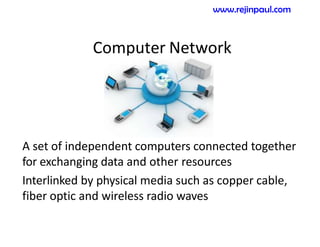
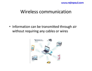
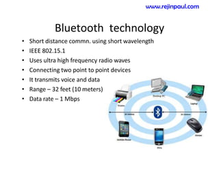
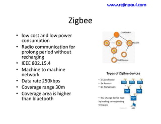
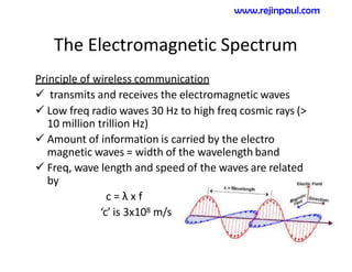
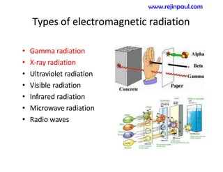
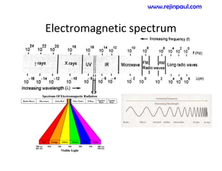
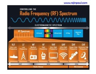
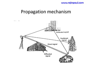
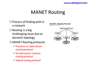
This document provides an overview of topics related to ad hoc and wireless sensor networks. It discusses fundamentals of wireless communication including different types of wireless networks like WLANs, Bluetooth, Zigbee. It also covers electromagnetic spectrum, propagation mechanisms, characteristics of wireless channels including path loss, fading and interference. Mobile ad hoc networks and wireless sensor networks are also listed as topics to be covered.
This document discusses solitons in optical fiber communication. It begins with an introduction to solitons as pulses that maintain their shape despite dispersion and nonlinearities. The history of discovering solitons in fiber optics is described, including key experiments in the 1980s and 1990s that demonstrated their use for long-distance, high-capacity data transmission. The document outlines how solitons form in fibers due to a balance between dispersion and the Kerr effect. It describes the properties and equations that characterize fundamental and higher-order soliton pulses. Parameters like dispersion length and peak power are also defined. Finally, the document discusses optimizing soliton width and spacing for high bit rates.
Attitude & orbital control system, TTC & M system, Power system, Communication subsystem, Satellite antenna, Space qualification, Equipment Reliability, redundancy
The document discusses the reflex klystron, a single cavity microwave oscillator. It consists of an electron gun, a cavity with grids, and a repeller plate. Electrons emitted from the cathode are accelerated through the cavity, undergo velocity modulation, and are repelled back through the cavity. This produces electron bunching and microwave oscillations. Applications include radar receivers, local oscillators, signal sources, and parametric amplifiers.
The document discusses limitations of vacuum tubes at microwave frequencies. Key limitations include increased parasitic inductance and capacitance from electrode leads, which reduce efficiency. Transit time effects also limit bandwidth as electrons oscillate between electrodes. Gain-bandwidth product remains constant, requiring alternative designs like reentrant cavities. Overall, vacuum tubes face challenges amplifying signals above 1 GHz due to these inherent timescale limitations. Solid state devices like transistors addressed these issues and enabled widespread microwave applications.
The document discusses satellite communication and provides details about various topics related to satellites. It begins with defining what a satellite is and describing different types of satellites. It then discusses the advantages of satellite communication over terrestrial communication. The document outlines the components of a satellite and how satellites stay in orbit. It also covers look angle determination, antenna types, link design, satellite orbits, applications, and the future of satellite communication.
This document discusses microwave devices, specifically directional couplers and isolators. It begins by defining microwaves and their applications such as telecommunications and radar. It then describes how directional couplers are passive devices that divide power through four ports and discusses their key figures of merit like coupling factor, isolation, and directivity. Isolators are also covered as two-port non-reciprocal devices that allow high power transmission in one direction while providing high attenuation in the opposite direction using Faraday rotation in a ferrite rod.
Small scale fading and multipath measurementsVrince Vimal
1. The document discusses small-scale fading and multipath measurements in wireless channels. It describes how fading occurs due to interference from multiple copies of transmitted signals arriving at the receiver at different times.
2. Key channel parameters that influence fading are discussed, including multipath propagation, Doppler shift caused by mobility, and signal bandwidth. Multipath signals have random amplitudes and phases that cause constructive and destructive interference as the receiver moves.
3. Techniques for measuring small-scale fading and multipath include using direct radio frequency pulses or spread spectrum channel sounding with a sliding correlator. Parameters extracted from power delay profiles include mean excess delay, root mean square delay spread, and coherence bandwidth.
This document discusses the applications of different radar frequency bands, ranging from HF to mm bands. It provides examples of common uses for each band, such as military communication in HF bands, air traffic control in VHF bands, weather radar and ship radar in S bands, Wi-Fi and satellite TV in C bands, and satellite communication, vehicle detection, and astronomy in Ku, K, Ka, V, W, and mm bands. The applications described indicate how specific frequency ranges are utilized for different wireless technologies and radar systems.
This document provides a course syllabus on mobile and wireless communications. The syllabus covers 4 units:
1) Wireless transmission fundamentals like frequencies, signals, and propagation effects
2) Multiplexing techniques including FDM, TDM, CDMA, and modulation methods
3) Access control mechanisms like FDMA, TDMA, CDMA and their performance
4) Wireless networks including satellite, WLAN, WATM networks and protocols
It also lists recommended textbooks for the course.
Radar uses radio waves to detect objects at a distance. There are two main types of radar: pulse radar, which transmits pulses and listens for echoes, and continuous wave radar, which relies on Doppler shifts. Key components of pulse radar include a transmitter, antenna, receiver and display. The pulse width and repetition frequency determine the radar's minimum and maximum detection ranges. Continuous wave radar requires separate transmit and receive antennas and detects targets by how their motion shifts the frequency of the received signal. Radar antennas concentrate energy into beams to improve accuracy. Reflectors and lenses are used to shape beams through constructive and destructive interference of radio waves.
This presentation gives complete idea about time domain analysis of first and second order system, type number, time domain specifications, steady state error and error constants and numerical examples.
Proximity sensors detect objects without physical contact using various technologies like inductive, capacitive, ultrasonic and optical. Inductive sensors detect metallic objects using a coil and oscillator to create a magnetic field. Capacitive sensors detect metallic and nonmetallic objects by measuring capacitance changes between the sensor and object. Ultrasonic sensors use sound waves above human hearing range, while optical sensors use light beams reflected off objects. Key features of good sensors include precision, accuracy, response speed, operating range, reliability, easy calibration and low cost.
Mathematical model for communication channelssafeerakd
This document discusses mathematical models for communication channels. It begins by showing a block diagram of a basic digital communication system and defines the key components. It then discusses different types of communication channels and mediums that can be used to transmit signals, including wires, wireless spectra, and optical fibers. The rest of the document discusses several common mathematical models used to represent communication channels, including additive noise channels, linear filter channels, and linear time-variant filter channels. It also discusses parameters that characterize channels and limits on data transmission rates. Finally, it covers optimum receivers for signals corrupted by additive white Gaussian noise.
RADAR uses radio waves to detect distant objects. It transmits pulses and measures properties of the reflected pulses, including range, angles, size, and speed of targets. RADAR signal processing involves measuring distance using transit time or frequency modulation, measuring speed using Doppler effect, and reducing interference through techniques like moving target indication and constant false alarm rate processing. The signal processor separates targets from clutter based on Doppler shifts and amplitude. RADAR has military, navigation, and civilian applications including air traffic control and law enforcement.
The document summarizes a seminar presentation on microwave signal generation. It discusses:
- Microwave signal generation using microwave tubes like klystrons, magnetrons, and travelling wave tubes, as well as solid state devices like Gunn diodes, IMPATT diodes, and TRAPATT diodes.
- The operating principles, frequency ranges, power outputs, and applications of these different microwave generation technologies.
- TRAPATT diodes in more detail, explaining their plasma avalanche operating principle, typical construction as a p+nn+ structure, and excitation using a current pulse to cause avalanche multiplication.
- A comparison of key specs and uses of IMPATT, TRAPATT,
This document provides an overview of electric circuit theory and electromagnetic field theory. It defines circuit theory as the study of electric systems and circuits, while electromagnetic theory examines electric and magnetic phenomena caused by electric charges. The basics of each theory are outlined, including their scientific models, fundamental laws, and basic quantities. The limitations of circuit theory and advantages of electromagnetic field theory are discussed. Key differences between lumped element circuits, distributed element circuits, drift velocity, and signal speed are also summarized.
This document discusses microwave communication and factors involved in microwave link design. It describes microwave communication as utilizing radio frequencies between 2-60 GHz for communication. Key factors in microwave link design include line-of-sight considerations, loss and attenuation calculations, fading predictions, and ensuring sufficient fade margin. Proper microwave link design is an iterative process that considers propagation losses, interference analysis, and ensuring quality and availability requirements are met.
The document discusses optical communication and fiber optic communication systems. It defines optical communication as using light to carry information over distances. The most common wavelengths used fall between 0.83-1.55 microns. Optical communication can be analog or digital. Fiber optic communication uses total internal reflection to transmit pulses of light through optical fibers to carry digital data. A fiber optic system includes a transmitter that converts electrical signals to light pulses and a receiver that converts the light pulses back to electrical signals.
Indoor propagation is necessary where outdoor propagation don't work perfectly like house, buildings, sports arena. Different material is used in different types of building then signal doesn't propagate as well as in outdoor. So There are different models for different Scenarios due to different environment, wall, etc.
Here are the steps to solve this problem:
1) The open-loop transfer function is given as:
G(s) = Kv/s
2) To reduce overshoot, we need to add a compensator to increase the damping. A lag compensator is suitable here.
3) A lag compensator has the transfer function:
Gc(s) = (s+z)/(s+p)
4) To reduce overshoot to less than 20%, we choose z=0.1 and p=0.05
5) The closed-loop transfer function is:
T(s) = Kv(s+0.1)/(s(s+0.05))
This document provides information about light propagation through optical fibers. It begins by defining an optical fiber as a cylindrical waveguide made of glass that uses total internal reflection to transmit light. It then discusses the fiber's core and cladding layers and the conditions needed for total internal reflection. The key points covered include:
- Light propagation is guided through the fiber core by total internal reflection at the core-cladding interface.
- Only rays entering the fiber core within the acceptance angle will continue propagating through total internal reflection.
- Electromagnetic mode theory is needed to fully understand light propagation in fibers. Discrete modes exist that are solutions to Maxwell's equations.
- The evanescent field that penetrates the cl
The document discusses digital communication systems. It provides examples of digital communication including an email sent to invite team members to a meeting. It then explains the key building blocks of a digital communication system including the input source, source encoder, channel encoder, digital modulator, channel, digital demodulator, channel decoder, source decoder and output transducer. The document also discusses channels used for digital communication, causes of signal loss, and comparisons between digital and analog communication systems.
Optical fiber communication involves transmitting light through thin glass or plastic fibers to carry information. Light is modulated to encode information and travels through the fiber's core via total internal reflection. At the receiver, the light is converted back to an electrical signal. Optical fibers allow much higher bandwidth than traditional copper cables and are immune to electromagnetic interference. Their small size and weight make them useful for long-distance telecommunications and high-speed networking.
Microwave devices can be passive or active. Passive devices include terminations to absorb microwave power without reflection, as well as directional couplers and phase shifters. Terminations include matched loads made of lossy materials placed in waveguides to absorb all incident power. Directional couplers are four-port devices that couple power between two connected waveguides in one direction only. Phase shifters provide a variable phase shift without changing the physical path length using materials like ferrites or dielectrics.
Laser communication uses lasers to transmit information through free space instead of fiber optic cables. It works similarly to fiber optics but transmits the beam through the atmosphere instead of cables. The transmitter converts signals into laser light and the receiver includes a telescope to capture the beam and detectors to convert it back into signals. Laser communication has advantages over radio frequency and fiber optics for applications where laying cable is not possible or practical such as for satellites, remote areas, and emergencies due to its high bandwidth, directivity, security, and smaller antenna size.
EC8702 adhoc and wireless sensor networks iv eceGOWTHAMMS6
This document outlines the syllabus for a course on Adhoc and Wireless Sensor Networks. It covers five units: (1) Introduction to Adhoc Networks and routing protocols, (2) Introduction to sensor networks and architectures, (3) Networking concepts and protocols for sensor networks, (4) Security issues in sensor networks, and (5) Sensor network platforms and tools. Some key topics discussed include characteristics of adhoc networks, challenges in routing, components and applications of wireless sensor networks, and medium access schemes. The objectives are for students to learn the fundamentals and apply their knowledge to identify suitable protocols based on network requirements and understand security and transport layer issues in these networks.
A loop antenna is a radio antenna consisting of a loop or coil of wire, tubing, or other electrical conductor with its ends connected to a balanced transmission line (or possibly a balun). There are two distinct antenna designs: the small loop (or magnetic loop) with a size much smaller than a wavelength, and the much larger resonant loop antenna with a circumference close to the intended wavelength of operation. Small loops have low radiation resistance and thus poor efficiency and are mainly used as receiving antennas at low frequencies. To increase the magnetic field in the loop and thus the efficiency, the coil of wire is often wound around a ferrite rod magnetic core; this is called a ferrite loop antenna. The ferrite loop is the antenna used in many AM broadcast receivers, with the exception of external loops used with AV Amplifier-Receivers and car radios; the antenna is often contained inside the radio's case. These antennas are also used for radio direction finding. In amateur radio, loop antennas are often used for low profile operating where larger antennas would be inconvenient, unsightly.
(c) WIkipedia
This document discusses transmission fundamentals for data communications and networking. It defines key concepts such as data, signals, transmission, sources, destinations, and media. It explains how data can be transmitted through various media types including guided media like twisted pair, coaxial cable, and optical fiber as well as unguided media like radio waves, microwaves, and satellites. It also covers digital and analog signals, bandwidth, encoding data onto signals, and electromagnetic spectrum fundamentals.
1. RF VLSI design involves challenges balancing performance, cost, and functionality across disciplines like analog and digital circuits.
2. Key applications include WLAN, GPS, RFID, and satellite networks operating at frequencies from 900MHz to 10GHz.
3. RF transceivers upconvert and downconvert signals using oscillators and frequency synthesizers, and must deal with tradeoffs transmitting high power signals while sensing small received signals.
This document discusses different types of transmission media, including their characteristics and applications. It covers both guided media like twisted pair, coaxial cable, and optical fiber, as well as unguided or wireless transmission using radio frequencies, microwaves, and satellites. Key points discussed include the factors that determine transmission quality like bandwidth and interference, the advantages of higher bandwidth and fiber optics, and how different media are suited for various uses from local networks to long-distance trunks based on their data rates and transmission distances.
The attached narrated power point presentation explores the evolution and generations of fiber optics as well as recent trends in Optical Fiber Communications. An attempt has also been made to introduce a few emerging and exciting technologies in the area of Optical Communications. The material will be useful to KTU final year B Tech students who prepare for the subject EC 405, Optical Communications.
Transmission media carry signals between communication devices and come in both physical and wireless forms. Physical media include twisted pair cable, coaxial cable, and fibre optic cable which carry signals through physical wires or strands. Wireless media transmit signals through the air using technologies like broadcast radio, cellular networks, Bluetooth, WiFi and satellites. Each transmission medium has different characteristics like bandwidth, transfer rate and suitability for different communication needs which make some better than others depending on the situation.
There are two main types of transmission media: guided and unguided. Guided media includes twisted pair cable, coaxial cable, and fiber optic cable which direct signals along a physical path. Unguided media uses wireless transmission such as radio waves, infrared, Bluetooth, WiFi, satellite. Each media type has advantages and limitations in bandwidth, distance capability, data rate, and susceptibility to interference. Fiber optic cable can support the greatest bandwidth over longest distances. Wireless technologies trade mobility for shorter range and potential interference issues.
Transmission media can be either wired (guided) or wireless (unguided) and are used to transmit signals from one device to another. Wired media include twisted pair, coaxial cable, and fiber optic cable. Wireless media transmit electromagnetic waves without a physical conductor and include radio waves, microwaves, and infrared. The type of media used depends on factors like bandwidth, distance, data rate, susceptibility to interference, and cost. Each media has its own advantages and limitations for different communication applications.
This document discusses different types of transmission media used in computer networks. It describes various cable types including twisted pair, coaxial, fiber optic and their characteristics. It also covers wireless transmission media like radio waves, microwaves, infrared and compares different media based on cost, speed, attenuation and interference. The document provides details on network cabling standards, fiber optic connectors, wireless frequency bands and antenna types. It concludes with comparisons of wired and wireless media.
Yankee Stadium implemented a wireless infrared LAN to connect cash registers to a central server for food ordering. Infrared was chosen for its low cost and ability to operate within the stadium without interfering with games. However, infrared has short range and low speeds, limiting its use to this localized application within the stadium.
The document discusses various transmission media including guided media like twisted pair, coaxial cable, and optical fiber as well as unguided media such as wireless transmission and radio. It provides details on characteristics of each medium such as data rates, distance capabilities, attenuation over frequencies, and applications. The document also reviews concepts of electromagnetic waves and provides examples of using different media for applications like local and wide area networks.
This document provides an overview of optical fiber communications. It discusses the history of fiber optics, including how fiber transmission improved on electrical transmission. The key advantages of optical fibers are described. The electromagnetic spectrum is shown, focusing on the optical spectral bands used for fiber communications. The document outlines the windows and spectral bands designated for fiber optic links. It also discusses network information rates and standards for optical fiber communications.
There are two main types of transmission media: guided and unguided. Guided media like twisted pair cable and coaxial cable have a physical path that signals travel along, while unguided media like wireless transmission propagate through free space. Key factors that determine the performance of a transmission medium include its bandwidth, data rate, distance capabilities, and susceptibility to interference. Common guided media include twisted pair, coaxial cable, and optical fiber, each with their own characteristics and applications for voice, data, and video transmission. Unguided or wireless transmission uses antennas to radiate signals through the air across a variety of frequency bands for applications like radio, TV, satellite, and infrared transmission.
Sept 2017 communication system and protocolsshahin raj
Photonics involves the control and use of photons in various applications. It includes optoelectronics, which uses light in electronics; quantum electronics, which involves light-matter interaction in devices like lasers; and quantum optics, which studies light's quantum properties. Photonic communications specifically applies these photonic technologies to transmit information over long distances using fiber optics. Fibers allow extremely wide bandwidth, are small and lightweight, provide immunity to electromagnetic interference, and enable transmission rates over 1 Gbit/s. Communication protocols and digital/analog transmission ensure error-free and efficient routing of data between senders and receivers.
This document summarizes key concepts about transmission media from William Stallings' 7th edition textbook. It discusses guided media like twisted pair, coaxial cable, and optical fiber as well as unguided wireless transmission. Key factors in transmission media include bandwidth, attenuation, interference, and number of receivers. Guided media have advantages for higher data rates over longer distances while wireless has benefits for mobility but shorter range.
Transmission media can be guided or unguided. Guided media include twisted pair cable, coaxial cable, and optical fiber, which use wires or fibers to direct signals over distance. Unguided media transmit signals wirelessly using technologies like radio waves, microwaves, and satellites. The document discusses the characteristics, applications, advantages, and limitations of various transmission media types.
This document discusses different types of transmission media used for data communication. It describes guided media such as twisted pair, coaxial cable, and optical fiber, as well as unguided or wireless transmission using antennas. Key points covered include the characteristics, applications, and advantages/disadvantages of each transmission medium. Twisted pair is commonly used for short-range connections while optical fiber can support very high data rates over long distances. Unguided transmission uses different frequency bands for applications like radio broadcasting, microwave links, and satellite communication.
Guided media uses cabling to guide data signals along a specific path. The three main types of guided media are twisted pair cable, coaxial cable, and optical fiber. Unguided or wireless media transmits electromagnetic signals through free space without a physical medium. Common types of wireless media include radio waves, microwaves, and infrared waves.
1. Guided media uses cabling to guide data signals along a specific path, including twisted pair cable, coaxial cable, and optical fiber.
2. Unguided or wireless media transmits electromagnetic signals through free space without cabling, including radio waves, microwaves, and infrared waves.
3. Common examples of wireless transmission media are WiFi networks using radio waves, cellular networks and satellite TV using microwaves, and TV remotes using infrared signals.
Similar to EC8702-ADHOC AND WIRELESS SENSOR NETWORKS-UNIT NOTES.pdf (20)
KuberTENes Birthday Bash Guadalajara - K8sGPT first impressionsVictor Morales
K8sGPT is a tool that analyzes and diagnoses Kubernetes clusters. This presentation was used to share the requirements and dependencies to deploy K8sGPT in a local environment.
Introduction- e - waste – definition - sources of e-waste– hazardous substances in e-waste - effects of e-waste on environment and human health- need for e-waste management– e-waste handling rules - waste minimization techniques for managing e-waste – recycling of e-waste - disposal treatment methods of e- waste – mechanism of extraction of precious metal from leaching solution-global Scenario of E-waste – E-waste in India- case studies.
DEEP LEARNING FOR SMART GRID INTRUSION DETECTION: A HYBRID CNN-LSTM-BASED MODELgerogepatton
As digital technology becomes more deeply embedded in power systems, protecting the communication
networks of Smart Grids (SG) has emerged as a critical concern. Distributed Network Protocol 3 (DNP3)
represents a multi-tiered application layer protocol extensively utilized in Supervisory Control and Data
Acquisition (SCADA)-based smart grids to facilitate real-time data gathering and control functionalities.
Robust Intrusion Detection Systems (IDS) are necessary for early threat detection and mitigation because
of the interconnection of these networks, which makes them vulnerable to a variety of cyberattacks. To
solve this issue, this paper develops a hybrid Deep Learning (DL) model specifically designed for intrusion
detection in smart grids. The proposed approach is a combination of the Convolutional Neural Network
(CNN) and the Long-Short-Term Memory algorithms (LSTM). We employed a recent intrusion detection
dataset (DNP3), which focuses on unauthorized commands and Denial of Service (DoS) cyberattacks, to
train and test our model. The results of our experiments show that our CNN-LSTM method is much better
at finding smart grid intrusions than other deep learning algorithms used for classification. In addition,
our proposed approach improves accuracy, precision, recall, and F1 score, achieving a high detection
accuracy rate of 99.50%.
ACEP Magazine edition 4th launched on 05.06.2024Rahul
This document provides information about the third edition of the magazine "Sthapatya" published by the Association of Civil Engineers (Practicing) Aurangabad. It includes messages from current and past presidents of ACEP, memories and photos from past ACEP events, information on life time achievement awards given by ACEP, and a technical article on concrete maintenance, repairs and strengthening. The document highlights activities of ACEP and provides a technical educational article for members.
Optimizing Gradle Builds - Gradle DPE Tour Berlin 2024Sinan KOZAK
Sinan from the Delivery Hero mobile infrastructure engineering team shares a deep dive into performance acceleration with Gradle build cache optimizations. Sinan shares their journey into solving complex build-cache problems that affect Gradle builds. By understanding the challenges and solutions found in our journey, we aim to demonstrate the possibilities for faster builds. The case study reveals how overlapping outputs and cache misconfigurations led to significant increases in build times, especially as the project scaled up with numerous modules using Paparazzi tests. The journey from diagnosing to defeating cache issues offers invaluable lessons on maintaining cache integrity without sacrificing functionality.
CHINA’S GEO-ECONOMIC OUTREACH IN CENTRAL ASIAN COUNTRIES AND FUTURE PROSPECTjpsjournal1
The rivalry between prominent international actors for dominance over Central Asia's hydrocarbon
reserves and the ancient silk trade route, along with China's diplomatic endeavours in the area, has been
referred to as the "New Great Game." This research centres on the power struggle, considering
geopolitical, geostrategic, and geoeconomic variables. Topics including trade, political hegemony, oil
politics, and conventional and nontraditional security are all explored and explained by the researcher.
Using Mackinder's Heartland, Spykman Rimland, and Hegemonic Stability theories, examines China's role
in Central Asia. This study adheres to the empirical epistemological method and has taken care of
objectivity. This study analyze primary and secondary research documents critically to elaborate role of
china’s geo economic outreach in central Asian countries and its future prospect. China is thriving in trade,
pipeline politics, and winning states, according to this study, thanks to important instruments like the
Shanghai Cooperation Organisation and the Belt and Road Economic Initiative. According to this study,
China is seeing significant success in commerce, pipeline politics, and gaining influence on other
governments. This success may be attributed to the effective utilisation of key tools such as the Shanghai
Cooperation Organisation and the Belt and Road Economic Initiative.
Harnessing WebAssembly for Real-time Stateless Streaming PipelinesChristina Lin
Traditionally, dealing with real-time data pipelines has involved significant overhead, even for straightforward tasks like data transformation or masking. However, in this talk, we’ll venture into the dynamic realm of WebAssembly (WASM) and discover how it can revolutionize the creation of stateless streaming pipelines within a Kafka (Redpanda) broker. These pipelines are adept at managing low-latency, high-data-volume scenarios.
Embedded machine learning-based road conditions and driving behavior monitoringIJECEIAES
Car accident rates have increased in recent years, resulting in losses in human lives, properties, and other financial costs. An embedded machine learning-based system is developed to address this critical issue. The system can monitor road conditions, detect driving patterns, and identify aggressive driving behaviors. The system is based on neural networks trained on a comprehensive dataset of driving events, driving styles, and road conditions. The system effectively detects potential risks and helps mitigate the frequency and impact of accidents. The primary goal is to ensure the safety of drivers and vehicles. Collecting data involved gathering information on three key road events: normal street and normal drive, speed bumps, circular yellow speed bumps, and three aggressive driving actions: sudden start, sudden stop, and sudden entry. The gathered data is processed and analyzed using a machine learning system designed for limited power and memory devices. The developed system resulted in 91.9% accuracy, 93.6% precision, and 92% recall. The achieved inference time on an Arduino Nano 33 BLE Sense with a 32-bit CPU running at 64 MHz is 34 ms and requires 2.6 kB peak RAM and 139.9 kB program flash memory, making it suitable for resource-constrained embedded systems.
EC8702-ADHOC AND WIRELESS SENSOR NETWORKS-UNIT NOTES.pdf
1. EC8702
Ad Hoc and Wireless Sensor Networks
UNIT-I AD HOC NETWORKS –
INTRODUCTION AND ROUTING PROTOCOLS
www.rejinpaul.com
2. Computer Network
A set of independent computers connected together
for exchanging data and other resources
Interlinked by physical media such as copper cable,
fiber optic and wireless radio waves
www.rejinpaul.com
4. • Topics to be covered:
1. Fundamentals of Wireless communication
2. Electromagnetic Spectrum
i. Types
ii. Frequency Bands
iii. Spectrum allocation methods
3. Radio Propagation mechanisms
i. Reflection
ii. Diffraction
iii. Scattering
4. Characteristics of Wireless channel.
5. Mobile Adhoc Networks (MANET)
6. Wireless Sensor Networks (WSN)
www.rejinpaul.com
5. 1. Fundamentals
• Users can communicate from remote areas
• Information can be communicated without
wires, cables or any electrical conductors
• Examples of wireless devices are
Cordless telephones
Mobiles
GPS units
Satellite television
Wireless computer parts
www.rejinpaul.com
8. Difference between wired and wireless
communication
• Wired N/W
Ethernet cable
• Wireless n/w
Infrared / radio frequency signals
www.rejinpaul.com
11. Advantages
• Self configuring
• Easy to use
• Communication has enhanced due to convey the
information very quickly
• Military areas, flooded areas, hazardous area
etc..
• Medical applications…
www.rejinpaul.com
14. Disadvantages
More attack by unauthorized users
Requires strong security protocols.
Disturbed by abnormal climate, noise interference etc..
Limited bandwidth
Stability of network is less
Speed is slower
Coverage problem etc
www.rejinpaul.com
15. Types of wireless communication
• Infrared wireless communication
• Cellular systems
• Cordless phones
• WLANs
• Satellite communication
• Bluetooth technology
• Zigbeee
• WiMax
www.rejinpaul.com
16. Infrared wireless communication
• Infrared waves are used
• Short to medium range
communication
Features:
Line of sight
communication
Intrusion detectors
Motion detectors
Home entertainment
control units
Medical diagnostic devices
Headsets, modems,
printers etc..
www.rejinpaul.com
17. Cellular systems
• 1960 - Analog communication
•Provide voice and data communication
Working
Coverage area is divided into non-overlapping
cells – mobile devices
Fixed point base station
Mobile switching center – allocating channels
www.rejinpaul.com
18. Various levels…
• 1G- Advanced Mobile Phone Services (FDMA+
30KHz FM modulated voice channel)
• 2G – Global System for Mobile communication
(100kbps)
• 3G- different data rate depends on the
mobility and location
www.rejinpaul.com
19. Cordless phones
• 1970s - initiated
• Low cost and short wireless link
• Radio waves with specific frequency
• Specific distance from base station
• It uses Base station and handset
• BS call as Electrical signal– radio signal–
handset of the user
• Radio signal – electrical signal – speaker -
sound form
• Base station & handset --- > frequency pair
www.rejinpaul.com
20. Wireless LAN
• It link more wireless devices by wireless
distribution method
• Limited area – home, school computer lab,
office building etc..
• IEEE 802.11 standard – high frequency radio
waves
• WLAN – LAWN
• WLAN – AP – internet
www.rejinpaul.com
21. Cond….
• AP- transmits and receives the radio
frequency signals - routers
• AP -- client
• Clients – several devices….
• CSMA/CA for path sharing also include
encryption method -- security
www.rejinpaul.com
22. Satellite communication
• It connect any where on the earth
• It rotate around the earth for gathering and
transmitting useful information
Working Principle
• Satellite (sensors) earthstation
• Earth station – GHz signals Satellite
• Satellite – signal to earth (all stations with in
coverage area)
• Tracking and command system – uplink and
down link
• Bigger in size, consumes more power and more
expensive
www.rejinpaul.com
23. Bluetooth technology
• Short distance commn. using short wavelength
• IEEE 802.15.1
• Uses ultra high frequency radio waves
• Connecting two point to point devices
• It transmits voice and data
• Range – 32 feet (10 meters)
• Data rate – 1 Mbps
www.rejinpaul.com
24. Zigbee
• low cost and low power
consumption
• Radio communication for
prolong period without
recharging
• IEEE 802.15.4
• Machine to machine
network
• Data rate 250kbps
• Coverage range 30m
• Coverage area is higher
than bluetooth
www.rejinpaul.com
25. WiMAX
-
• Worldwide process for Microwave access
broadband wireless technology
• IEEE 802.16
• Data rate 30-40 Mbps
• Higher speed over greater distance
www.rejinpaul.com
26. The Electromagnetic Spectrum
Principle of wireless communication
transmits and receives the electromagnetic waves
Low freq radio waves 30 Hz to high freq cosmic rays (>
10 million trillion Hz)
Amount of information is carried by the electro
magnetic waves = width of the wavelength band
Freq, wave length and speed of the waves are related
by
c = λ x f
‘c’ is 3x10⁸ m/s
www.rejinpaul.com
32. Low frequency bands
• Radio waves
• Micro waves
• Infrared waves
• Visible light portions
www.rejinpaul.com
33. Radio waves
• Long distance communication – cross the
buildings easily
• Omni directional – no need to align
transmitter and receiver
www.rejinpaul.com
35. Gamma rays
• Wavelength : <0.01nm
• Highest frequency
• Medical applications - treat the cancer patient
• Produced by atomic nucleus
www.rejinpaul.com
36. Ultraviolet radiation
• Wavelength: 400 nm -10nm
• Sun and hot stars emitted UV rays
• VLF,LF and MF ground waves few100km
• HF and VHF are observed – near the earth
surface
• Sky wave radio wave reflected fromthe
ionosphere -- > military communication
www.rejinpaul.com
37. X-rays
• Wavelength : 0.01nm to 10nm
• Temp: million to 10 million degree
• Generated by super heated gas from
exploding stars
• Produced by accelerating electrons
www.rejinpaul.com
38. Auctioning method
• Allocated based on higher bidding company in
auction
Example
ITU designed ISM frequency bands for unlimited
usage – wireless LAN
www.rejinpaul.com
39. Radio Propagation Mechanisms
• Radio waves with different frequencies ->
propagate in different ways
• wave length compared to the dimension of
the building
• Propagation mechanisms are,
Reflection
Diffraction
Scattering
www.rejinpaul.com
41. Reflection
• Electromagnetic waves – hit on an object
(larger dimension> wavelength)- reflected
wave
• 180 degree phase shift b/w incident wave and
reflected wave
www.rejinpaul.com
42. Diffraction
• Waves hit an edge of the object – propagated
in different direction
• Hit in Impenetrable (hidden) object –
diffraction
• Amount of diffraction is frequency dependent
• Low frequency -- > diffraction more
www.rejinpaul.com
43. Scattering
• Waves hit at irregular objects ( trees, walls
with rough surfaces, furniture and vehicles)
• Propagate into number of outgoing weaker
signal
www.rejinpaul.com
44. Characteristics of Wireless channel
• Path loss
Free space propagationmodel
Realistic path loss model
Two-ray model
• Fading
Fast fading
Slow fading
• Interference
Adjacent channel interference
Co-channel interference
Inter-symbol interference
• Doppler shift
• Transmission rate constraints
Nyquist’stheorem
Shannon’stheorem
www.rejinpaul.com
45. Path loss
• Ratio of transmitted power to received power
• Expressed in dB
• Depends on the radio frequency and nature of the ground
www.rejinpaul.com
48. Free space propagation model
• Direct path between sender and receiver
• Free space path loss
• Transmitted power – Pt
• Transmitted gain - Gt
• Received power - Pr
• Received gain - Gr
Relation between transmitted power and receiver
power
• Pr = Pt Gt Gr (λ/4πd)2
www.rejinpaul.com
49. Realistic path loss model
• Various propagation effects
• Maxwell’s equations – complex algorithms
and intensive operations
www.rejinpaul.com
50. Two-ray model
• Line of sight path & reflected path
Pr = Pt Gt Gr (hthr/d2)2
Pr = Pt Gt Gr (λ/4π)2 (1/dγ)
www.rejinpaul.com
51. Fading
• Fluctuations in signal strength when received
by the receiver.
Fast fading/ Small scale fading
Slow fading/Large scale fading
www.rejinpaul.com
52. Fast fading
(different version of tx-ed signal)
• Fast fluctuations in amp, phase and delay of the received
signal.
• Fluctuations due to ?
• Interference between multiple copies of the same transmitted
signal reaching the receiver at a little different times.
• Occurs due to three propagation mechanisms
www.rejinpaul.com
53. Slow fading (object blockings)
• Shadow fading
• Receiver inside the building or transmitted signal pass through
the wall
• Little variation in received power
www.rejinpaul.com
54. Interference
• Interaction of waves that are correlated with each
other.
• Either they travel from the same source
• Or they have same frequency.
• This incident occurs when two waves meet at a point
while traveling along the same transmission medium.
– Adjacent channel interference
– Co-channel interference
– Inter symbol interference
www.rejinpaul.com
55. Adjacent channel interference
• Near by freq interfere with on-going
transmission signal
• Avoided by using guard band
www.rejinpaul.com
56. Co-channel interference
• Narrow band interference
• Same frequency can be
reused by nearby systems
• Avoided by multiuser
detection mechanism,
directional antennas and
dynamic channel allocation
mechanisms
www.rejinpaul.com
57. Inter symbol interference
• Distortion in telecommunication
• One or more symbols interfere with other
symbol
• Due to multipath propagation and consequent
overlapping of individual pulses – blur or
mixture of signal
• Adaptive equalization – allocate the time to
each pulses
www.rejinpaul.com
61. Transmission rate constraints
• Todetermine the maximum data rate of
transmission
• Nyquist’s theorem
• Shannon’s theorem
www.rejinpaul.com
62. Nyquist’s theorem
• Gives the maximum data rate of the channel
(noiseless)
• Number of changes (values or voltages of the
transmitted signal) per second – baud rate
• Ex:
Transmission value 0,1,2,3 --- 00,01,10,11
C = 2xBxlog2L bits/sec
B= bandwidth
L= Number of discrete signal levels/ voltage levels
www.rejinpaul.com
63. Shannon’s Theorem
• Find the data rate of noise channel
SNR = 10log10(S/N)
Channel capacity
C = Bxlog2(1+(S/N)) bits/sec
www.rejinpaul.com
64. Basic concepts of Ad Hoc
Networks
•What is adhoc network ?
It is a network which is formed
Without any central infrastructure.
•Adhoc network can be formed ?
Instantly
•Communication can be carried out using ?
Radio waves.
•Any where & Any time.
•Dynamic topology
•Data can be exchanged by wireless interface
www.rejinpaul.com
65. MANET Communication
• Single hop communication- direct
• Multi hop communication- for away source
node
www.rejinpaul.com
66. PROTOCOLS
• 1970- Norman Abramson & co – ALOHA –
Single hop
• 1973 – DARPA(DEFENCE RADIO) – PRNET –
Multi hop
• PRNET(PACKET RADIO NETWORK)
– ALOHA + CSMA : to access the common
wireless channel
• IETF – ad hoc working group – standard
protocol & functional specifications
www.rejinpaul.com
67. Types of wireless N/W
• Infrastructure based network
• Infrastructure less network
www.rejinpaul.com
68. Infrastructure based network
• Nodes – fixed base station (APs)
• Ex: Cellular N/W
• N/W area – cells
• BS – coverage area to each cell
www.rejinpaul.com
69. Infrastructure less network
• Communicate without any fixed infrastructure
• MANETs and (Vehicular)VANETs
• Each node act as router
www.rejinpaul.com
71. Applications of ad hoc N/W
• Military applications
• Emergency services
Disaster relief efforts
Flooded areas
• Commercial applications
Industries
On line payment
• Education
Conferences
Virtual class rooms
www.rejinpaul.com
75. • Military applications
soldiers – safety vehicles
• Emergency services
search and rescue operations also fire fighting areas
• Commercial applications
Data base maintenance in industry as well as on-
line payment for e-commerce applications
• Education
For organizing conferences, meetings, lectures,
virtual class rooms etc -- in universities, school &
colleges
www.rejinpaul.com
76. Design issues in ad hoc wireless N/Ws
• Medium access scheme
• Routing
• Multicasting
• Transport layer protocol
• Pricing scheme
• QoS
• Self-organization
• Security
• Addressing and service discovery
• Energy management
• Deployment considerations
www.rejinpaul.com
81. Medium access scheme
• Distributed operation
• Synchronization
• Hidden terminal problem
• Exposed terminal problem
• Throughput
Access delay
• Real time traffic support
• Resource reservation
• Ability to measure resource
availability
• Capability for power control
• Adaptive rate control
• Use of directional antennas
www.rejinpaul.com
82. Routing
• Route selected based on hop
count
Requirements of routing
Minimum delay
Quick route configuration
Loop free routing
Distributed routing approach
Minimum control overhead
Scalability
QoS
Time sensitive traffic and security
Major design issues
Mobility
Bandwidth constraint
shared channel
Battery power
Storage capacity
www.rejinpaul.com
83. Multicasting
• What is Multicasting ?
Transmission of Same
message
• To ?
A group of mobile nodes
• In ?
Single transmission.
Major design issues
• Efficiency
• Control overhead
• QoS
• Scalability and security
www.rejinpaul.com
84. Transport layer protocol
• Protocols are used to Set up and maintain ?
End-to-end connection.
• Focus on?
Flow control and congestion control
• What is TCP ?
• Transfer Control Protocol.
• It is a connection oriented protocol.
• Used in ?
• Wired Networks.
• Performance in TCP is degraded due to
frequent path breaks
High mobility
Bandwidth
Power
Channel error rate
Frequent network partitions
• TCP is divided into two – More packet loss
www.rejinpaul.com
85. • Performance in TCP is
degraded due to
frequent path breaks
High mobility
Bandwidth
Power
Channel error rate
Frequent network
partitions
www.rejinpaul.com
87. QoS
• If there is a better coordination and cooperation between ?
- Service provider and the user
- then high QoS can be achieved.
QOS can differ from application to application.
• Bandwidth and delay are important parameters for ?
• Multimedia applications
• Identifying trusty nodes and routing packets through them are
key parameters of ?
• Defense applications.
• Multiple link disjoint paths and availability are the key
parameters of ?
• Emergency and rescue operations related applications.
www.rejinpaul.com
88. Self-organization
• Self – configure
• Self Organization includes ?
- Neighbour discovery.
- Topology organization.
- reorganization
• Topology can be varied – high mobility, node
failures and frequent N/W partitioning
• Every node maintain the updated information
• Beacon signals – transferred to all nodes
www.rejinpaul.com
89. Security
• Passive attack :
• Caused by ?
• Malicious nodes present in the network.
• Toobtain ?
• Information being exchanged in network.
• This type of attacks would not disturb network operation.
• Active attack - disturb the N/W operation
Internal attack –attackers within the network
External attack - attackers external the network.
• Some other security threats are ?
-DoS (Denial of service)
- Information disclosure and interference.
www.rejinpaul.com
90. Addressing and service discovery
• Address of mobile node is ?
Globally unique identifier
• Used for ?
Communication in Adhoc network.
• Since nodes join into a ?
new network and leave from the current network any time
• Any auto configuration scheme is required to ?
Allocate non duplicate addresses to the nodes.
• Adhoc n/w also requires ?
A duplicate address-detection mechanism
• In order to maintain ?
Unique addressing throughout the network.
www.rejinpaul.com
91. Energy management
• In a node,
• It is the process of managing ?
- the sources and consumers
• Of ?
- energy
• To ?
- boost up the lifetime of the node in the network.
Four categories.
• Transmission power management
• Battery energy management
• Processor power management
• Device power management
• Functions of energy management mechanisms are ?
• Battery life enhancing of a node
• Determine the routing path with minimum energy consumption.
www.rejinpaul.com
92. Deployment considerations
• Low cost deployment
• Short deployment time
• Re-configurability
• Non-estimation of future traffic
www.rejinpaul.com
93. Types of Wireless Ad-hoc network
• Mobile ad hoc networks
• Wireless sensor networks
• Wireless mesh networks
www.rejinpaul.com
94. • Wireless Sensor Network (WSN) research has enabled large
scale monitoring using small Sensors with radio links.
• The technological advance in wireless communications and
microelectronics has enabled the development of small, low-
cost Sensor Nodes.
• Wireless Sensor Networks are developed to organize and
control these Sensor Nodes, which have sensing, data
processing, communication and control capabilities.
Information collected from these Sensor Nodes is routed to a
sink Node via wireless communication approach.
www.rejinpaul.com
101. Mobile Ad Hoc Networks
• Basic concepts:
-Self configuring & decentralised n/w
-Each node– router
-Topology- dynamic topology
-installation- not require preplanning
MANET- interconnected to Internet
-Different services to the users.
www.rejinpaul.com
107. • Networking:
Wired n/ w routing protocol- not suitable for MANET
Re –design protocol-
Toimprove robustness and adaptability
Enabling tech/ are used to provide end to end reliable
data delivery.
Locating receiver node is difficult- high mobility.
Localization mechanism-determine location of a mobile
node.
www.rejinpaul.com
108. • Middleware and applications:
Its is developed to rely on each
Application to handle all the services.
Specialized fields:
Emergency services.
Disaster recovery.
Environmental monitoring.
Widely used in:
Home n/w
search and rescue operation.
Educational applications
www.rejinpaul.com
109. MANET Operations
Each node act as router
Exchanges its own information to its
neighbors as beacon messages
Discover forwarder nodes to forward packets
Broadcast the packet to all other neighbors
which are in its transmission range
Mobile can join the network and leave the
network at any time
www.rejinpaul.com
110. MANET Routing
Process of finding path in
a network
Routing is a big
challenging issue due to
dynamic topology
MANET Routing protocols
Proactive or table-driven
routing protocol
On-demand or reactive
routing protocol
Hybrid routing protocol
www.rejinpaul.com
111. Proactive or table-driven routing
protocol
• Each node maintains a routing
table to update the details of
its neighbors
• Each node exchanges hello
packet ( which includes node
identifier, message)
• Based on hello message
information, node updates the
routing table
• Easily find the route between
transmitter and receiver
• Reduce the time to determine
the route
• Ex: DSDV(Destination
sequenced distance vector)
www.rejinpaul.com
113. On-demand or reactive routing protocol
• Each node determines a routing path
• Each protocol uses two key phases
Route discovery
Route maintenance
Route discovery
It uses route request and route reply messages
Route maintenance
If reliable path is broken, route maintenancephase
can be used
It send the route error message to sender for
intimating the broken route
ex: Dynamic Source Routing Protocol
Ad hoc On demand Distance Vector
www.rejinpaul.com
115. Hybrid routing protocol
• It combines the advantages of proactive
and reactive routing protocols
• Within coverage area – Proactive
• Communicate with out of coverage -
Reactive
• Ex: Zone Routing Protocol
Order One MANET Routing Protocol
www.rejinpaul.com
116. Applications of MANET
• Commercial Environments
E- commerce
Business
Vehicular services
• Home and enterprise networking
• Educational applications
Set up virtual class rooms
Set up communication during conferences, official
meetings etc
• Disaster management
• Medical emergency
• Military applications
www.rejinpaul.com
119. WSN
Distributed network
Formed by small, lightweight wireless nodes
It is deployed to monitor the environment
For measuring the physical parameters like
temperature, pressure, humidity, sound, characteristics
of objects and their motion
WSN is configured automatically with out any human
intervention
Sensor nodes are small, powerful and inexpensive
It performs multi-hop communication
Coverage area is limited due to low energy and simple
antenna
For data transmission, each node has to form ad hoc
network
WSN is a special type of MANET
www.rejinpaul.com
126. Communication subsystem
• It is responsible for exchanging the
processed message with neighboring
sensor nodes
www.rejinpaul.com
127. Advantages
• Many sensor nodes are sensing same
event which tends to fault tolerant
• Data dissemination – Spreading
information
• Data gathering
www.rejinpaul.com
128. Limitations
• Cannot be protected from physical attack
• have very little storage capacity
• Works in short communication
• It provide little energy
• troubled processing power
www.rejinpaul.com
132. Terrestrial WSNs
m
e
d
Consists of hundreds to
thousands of WS nodes.
Deployed in Ad-Hoc or
structured manner-
communicating with base
station.
Sensor nodes dropped fro
a plane and randomly plac
into target area.
In preplanned deployment,
grid deployment,2-d, 3-d
placement models are used.
www.rejinpaul.com
133. Underground WSNs
• No. of sensor nodes- hidden in the
ground.
• Monitor underground conditions.
• Nodes- more expensive than terrestrial
WSNs.
• Maintenance, careful planning- require
high cost.
• Suitable components- reliable
communication-soil, rocks and other
mineral components.
www.rejinpaul.com
137. Cond…
• Communication between underground
sensor nodes-big challenge
• Due to signal losses and high level
attenuation.
• Require sink nodes to fwd message from
the sensor nodes to the base station.
• Limited battery power-very difficult to
recharge.
www.rejinpaul.com
138. Under water WSNs
• Consists of no. of sensor nodes and
vehicles.
• Under water vehicle are used-searching
and gathering data from sensor nodes.
• Sensor nodes –communicate themselves
– using acoustic waves.
• Acoustic waves are limited bandwidth,
long propagation delay, signal fading
problem.
www.rejinpaul.com
141. Multimedia WSNs
• Used to enable tracking and monitoring
purpose.
• Information in the form of imaging , video and
audio.
• Low cost sensor nodes equipped with
microphones and cameras.
• Challenges-high energy consumption, high
bandwidth Requirement, QoS, Data
processing and compression techniques.
www.rejinpaul.com
144. Mobile WSN
• Collection of mobile nodes.
• Have capability to compute, sense and
communicate with physical environment.
• Each mobile node can communicate with
other sensor nodes if it is in the visibility
of other sensor nodes.
• Data can be distributed using dynamic
routing.
www.rejinpaul.com
155. Design Challenges of Sensor
Networks
• 1) Sensor nodes are randomly deployed and
hence do not fit into any topology.
• Once deployed, do not require any human
intervention.
• Hence, setup and maintanence of the network
should be entirely autonomous.
www.rejinpaul.com
156. Design Issues/Challenges of WSN
• 2) Sensor networks are infrastructure less
networks.
• Therefore, all routing and maintanence
algorithms need to be distributed.
www.rejinpaul.com
157. Design Issues/Challenges of WSN
• 4) Sensor nodes are battery
driven.
• Difficult to change/recharge
• Usually deployed in remote
places.
• Design based on
applications to minimize the
energy consumption
• So as to increase the battery
life.
www.rejinpaul.com
158. Design Issues/Challenges of WSN
• 3) While designing sensor node , cost is also
an important factor to be considered.
www.rejinpaul.com
159. Design Issues/challenges of WSN
• 5) In forest sensor nodes
would be throwing from
aeroplane to deploy on
ground.
• In that situation, it is the
responsibiltiy of sensor
nodes to form ?
- network
- Connection
Identification
- Distribution
www.rejinpaul.com
160. Design Issues/challenges of WSN
• 7) Minimizing network life time for a prolong
period is a major design issue in WSNs.
• Thus the design of a good WSN needs to be
energy efficient.
www.rejinpaul.com
161. Design Issues/challenges of WSN
• 8) Toidentify the location of sensor nodes,
• Location discovery protocols are used.
• It must provide accurate location.
www.rejinpaul.com
162. Design Issues/challenges of WSN
• 9) Performing secured operations using sensor network is very critical.
• In ?
• Miltiary areas.
• Few issues are :
i) Secured key exchange
ii)key establishment
iii)authentication
iv) authorization
v) secure routing
vi) trust set up
vii) prevention of physical attack.
www.rejinpaul.com
163. Sensor Network Architecture
• A large number of sensors deployed on different areas
• Would form a network
• To?
• Communicate with Each other.
• Each sensor has a wireless communication capability.
• A sensor can gather information from?
• Other sensor nodes
• And can disseminate(broadcast) the processed information to?
• Other sensor nodes which is in the network.
• Architecture Types:
– Layered
– Clustured.
www.rejinpaul.com
166. • UNIFIED NETWORK PROTOCOL FRAMEWORK.
(UNPF)
• UNPF:
• It integrates 3 operations in its structure:
-Network initialization and Maintenance
protocol
- MAC
- Routing protocols
www.rejinpaul.com
167. Network initialization and
Maintenance protocol
• BS Can communicate with all
nodes
• Using ?
One hop communication
• Over ?
Shared media.
• BS broadcasts its identifier (ID)
• To ?
Sensor nodes using CDMA .
Sensor nodes which receive the
ID of BS will store the ID.
• As a response message:
• Each sensor node sends its ID at
lowest power level.
• This can be listened by BS at layer
one
• Because ?
• All the nodes are single hop
distance away from BS.
• Now, the BS broadcasts control
message to all the layer one
nodes with their ID.
• All sensor nodes send a beacon
message again.
www.rejinpaul.com
168. • Layer 1 nodes form layer two
• With ?
• Nodes which are one hop away from layer one nodes
• And records its ID’s.
• Layer -1 node inform this to ?
• BS of Layer-2 nodes
• Which in turn will broadcast to all the nodes.
• In this manner, the layered architecture can be built by BS and
Sensor nodes.
www.rejinpaul.com
169. MAC Protocol
• For the data transmission,
• Distributed TDMA Receiver Oriented Channel
(DTROC) assignment MAC protocol is used.
• Two operations of DTROC protocol are:
– Channel allocating
– Channel scheduling
www.rejinpaul.com
170. • Channel allocation:
- What it is?
It is the process
of ?
• Channel Scheduling:
• Sharing of ?
• Reception channel
• With ?
Assigning reception
channel
to ?
every node.
• Neighbours.
• DTROC uses suitable
channel allocating
algorithms.
•
www.rejinpaul.com
171. • Separate receiving channel is
assigned
• for ?
• each node
• by ?
• BS.
• Each node make ?
• transmission slot schedule and
broadcast to ?
• its neighbours
• thereby enabling ?
• collision free transmission and
saves energy.
www.rejinpaul.com
172. UNPF - R
• It makes the sensor nodes
• To ?
• Vary their communication range
• To ?
• Improve performance.
• Small transmission range would make many network
partitions
• Whereas, large Covered area may reduce spatial reuse of
frequencies.
www.rejinpaul.com
174. Clustured Architecture
• It organized the nodes in n/w into clusters.
• Each cluster contains – Cluster head
• Nodes in each cluster would Exchange
message within the cluster.
• Each cluster head can also communicate with
the BS which is an access point and connected
to a wired network.
www.rejinpaul.com
175. Clustered architecture
• Used in ?
• Sensor networks to achieve data fusion.
• Clustering can be extended to various numbers of depths
hierarchically.
• Data collected by all the cluster members can be fused to
cluster head and the resulting information can be
communicated to BS.
• The cluster formation and the selection of cluster heads are
fully autonomous and distributed process.
• This could be achieved through network layer protocols such
as Low-Energy Adaptive Clustering Hierarchy.
www.rejinpaul.com
176. • What is LEACH ?
• One of the clustering based protocols
• What it do ?
• It minimizes energy dissipation
• In ?
• Sensor networks.
www.rejinpaul.com
178. • In ad hoc network,
• Each node contends for common shared wireless channel.
• To ?
Transmit data packet @ the same time
• If all the nodes are starting to transmit data packet
simultaneously,
- Then data would be corrupted.
• So , a suitable shared medium access control mechanism has to
be deployed .
• In a such a way that all nodes share the common channel in an
efficient manner.
• This task can be performed by a protocol called MAC.
• Responsibility of MAC Protocol:
– Transmitting data packets from one device to another device across a shared
channel.
www.rejinpaul.com
179. Responsibilities of MAC protocol
• Allocation of wireless channel
• To ?
- Different nodes
- Which are competing at the same time.
• No node is waiting for prolong period.
• Operation is distributed.
• Performs framing, physical addressing, flow control and
error control
• Total available bandwidth is allocated efficiently
• Hidden and exposed terminal problem has to be
eliminated
www.rejinpaul.com
180. Condt..
• Maximization of utilization of channel
• Minimize the delay
• Support different types of traffic
• It should be robust in equipment failure and
N/W failure
• Require well power control
• Provide QoS support
• Provide time synchronization among nodes
www.rejinpaul.com
181. Design issues
• Bandwidth efficiency
Bandwidth is restricted – MAC
protocol is responsible- divide the bandwidth
into effective manner
Efficiency = bandwidth used for actual data
transmission/ total bandwidth
www.rejinpaul.com
183. QoS support
• Due to mobility of nodes from time to time
QoS is not effective
www.rejinpaul.com
184. Synchronization
• Transmission between the
sender and receiver nodes
• has to be synchronized for ?
- achieving error free
-Minimized packet loss
transmission.
• Synchronization is also
important in ?
- bandwidth reservation.
• It requires ?
-exchange of control
packets between sender
and receiver.
www.rejinpaul.com
192. Exposed terminal problem-
-block the current transmission due to neighboring
node transmit with some other node
www.rejinpaul.com
193. Error prone shared broadcast channel
• Due to each node broadcast the information
to be transmitted to designated receiver-----
• ----- Nodes do not start the communication
• Compete many nodes at a time
www.rejinpaul.com
194. • Lack of central coordination
• Mobility of nodes
www.rejinpaul.com
195. Classification of MAC protocols
• Contention – Based
Protocols
• Contention based
protocols with
reservation mechanism
• Contention based
protocols with
scheduling mechanism
www.rejinpaul.com
196. • Contention – Based
Protocols
• Contention based
protocols with
reservation mechanism
• Contention based
protocols with
scheduling mechanism
www.rejinpaul.com
200. Contention based protocols
• No nodes make prior reservation
• When node wants to transmit to other node-
compete with all other node – transmit
• Do not guarantee for QoS
Sender – initiated protocol
Receiver – initiated protocol
www.rejinpaul.com
202. Sender – initiated protocol
• Single channel sender
initiated protocol-
total bandwidth is not
divided
Multi- channel sender
initiated protocol –
bandwidth is divided
into several channels
www.rejinpaul.com
203. Receiver – initiated protocol
If receiver node ready to receive – initiate to
compete all the nodes to transmit the packets
www.rejinpaul.com
205. Contention based protocols with reservation
mechanism
• Provide guarantee for QoS
• Reserve the bandwidth prior
Synchronous protocols
Asynchronous protocols
www.rejinpaul.com
208. Synchronous protocol
• Time synchronization among all nodes
• So all nodes about reservation
www.rejinpaul.com
209. Asynchronous protocol
• Not required global time synchronization
• Use relative time information make
reservation
www.rejinpaul.com
210. Contention based protocols with
scheduling mechanism
• Packet scheduling at nodes
• Scheduling nodes for accessing the channel
www.rejinpaul.com
211. Contention based MAC protocol
• No reservation
• Compete all the nodes
• Node capture the channel – winning node
• Protocols are,
Media access protocol for wireless LAN
Floor acquisition multiple access protocols
Busy tone multiple access protocols
MACA – by invitation
Media access with reduced handshake
www.rejinpaul.com
212. Media access protocol for wireless LAN
• Protocols used in wireless LAN
MACA protocol
MACAW protocol
www.rejinpaul.com
214. • Channel busy – wait for
some time
• Channel idle – transmit
• Does not overcome
hidden and exposed
terminal problem
• Utilization of bandwidth
is less
www.rejinpaul.com
217. Solution to hidden & exposed terminal problem
By MACA protocol
www.rejinpaul.com
218. • Packet loss-
transmission.
• Nodes uses-Binary
Exponential Back off
algorithm.
• In BEB mechanism-
collision is detected.
• Nodes doubles the
maximum back-off
window.
www.rejinpaul.com
219. Solution to exposed terminal
problem
• B node ----- A node
• B node send RTS- A node--- heard by node C
• C node not actual receiver.- may not
response.
• C node can starts transmission
www.rejinpaul.com
220. IEEE 802.11
• What is this ?
• IEEE 802.11 refers to the set
of standards
• that define ?
Communication
• For ?
wireless LANs (wireless local
area networks, or WLANs).
• The technology behind
802.11 is branded to
consumers as Wi-Fi.
www.rejinpaul.com
221. WLAN provides support for ?
• Connection management
• Link reliability
• Power management in MANET.
• It uses three physical layer specifications which operate in ?
• 2400 to 2483.5 MHz band.
• 902-928 MHz
• 5.7 – 5.85 GHz region.
• 3 physical layers are ?
• FHSS-Frequency Hopping Spread Spectrum
• DSSS-Direct Sequence Spread Spectrum
• IF-Infrared Physical Layer.
• It deals with Physical and MAC layer in WLAN.
www.rejinpaul.com
222. Architecture
Operates into 2 modes:
• Infrastructure less
mode
• Infrastructure based
mode.
When two or more
stations communicate
with each other,
They form, Basic service
set (BSS).
www.rejinpaul.com
223. Physical layer of IEEE 802.11
• How many physical layers defined in 802.11 ?
• 3
• They are ?
• Radio techniques (2)
• IR (1)
• Radio techniques:
- 2.4 GHz ISM band.
- Increases reliability & throughput
www.rejinpaul.com
224. Physical Layer divided into?
• Two sublayers:
• Physical Medium Dependent sublayer (PMD)
• Physical layer convergence protocol sublayer (PLCP)
• PMD Performs:
-Encoding, Decoding , Modulation and Demodulation of
signals.
• PLCP provides:
-Service access point and a clear channel assignment carrier
sense signal to the MAC Layer of WLAN.
www.rejinpaul.com
225. MAC Layer
• 2 MAC Protocols used in WLAN.
• 1) Point Coordination Function (PCF)
• 2) Distributed Coordination Function (DCF)
• PCF:
- Centralized scheme
- Polling scheme
• DCF:
- Distributed scheme.
- Based on CSMA/CA
Hidden and exposed terminal problem can be avoided using handshaking
messages :
RTS & CTS
www.rejinpaul.com
226. IFS
• Time interval
• Between ?
the transmission
• Of ?
two successive frames
• By ?
Any node.
www.rejinpaul.com
227. • Short Inter Frame Spacing (SIFS)
• PCF Inter Frame Spacing (PIFS)
• DCF Inter Frame Spacing (DIFS)
• Extended Inter Frame Spacing (EIFS)
www.rejinpaul.com
228. SIFS
• Shortest IFS and takes highest priority to
access the medium.
www.rejinpaul.com
229. PIFS
• The waiting time values between SIFS and
DIFS.
www.rejinpaul.com
230. DIFS
• This amount of waiting time can be used by
the nodes if it operates under DCF mode.
www.rejinpaul.com
231. EIFS
• Extended Inter Frame Spacing :
• It is the longest IFS and gets least priority to
access the medium.
www.rejinpaul.com
251. Error Prone Shared
• Collision occur at node because of ?
• Hidden and exposed terminal problem.
21
www.rejinpaul.com
252. Types of ad hoc routing protocol
• Proactive or table driven routing protocols
• Reactive or on demand routing protocols
• Hybrid routing protocols
22
www.rejinpaul.com
253. Proactive
• Other name table driven routing
protocol
• Each node maintains a routing
table.
• Routing table contains up to date
routing information of the entire
network.
• Whenever a node wants to send
a packet to the receiver node,
- it looks up in own routing table
To ?
Find the routing table
To ?
Find the routing path
From ?
Itself to receiver.
Tables – Updated periodically.
To ?
Maintain the current stable/
available paths.
This can be achieved by ?
Exchanging or broadcasting the
periodic beacon signals between
nodes.
So that,
Each node can have the knowledge
about the complete network
topology.
Hence,
Each node can update its routing
table based on beacon signal it
has received from its negihbours.
23
www.rejinpaul.com
254. Reactive routing protocol
• On demand routing protocols
• Mixed:
• Best features of two.
24
www.rejinpaul.com
255. Proactive Routing Protocols
• Protocols which use the concept of Proactive
routing
– Destination sequenced distance vector routing
protocol
– Wireless routing protocol
– Cluster –head gateway switch routing protocol
– Fisheye state routing
25
www.rejinpaul.com
256. Destination sequenced distance
vector routing protocol
• @ DSDV Protocol in adhoc.
• One of the Popular proactive routing protocols
• DSDV-each node keeps record of route
information- form of routing table
26
www.rejinpaul.com
257. Each node contains....
• ID of destination node
• Details of next hop
• Metric
• Sequence number
• Time to live parameter
27
www.rejinpaul.com
258. Cond...
• Each route broadcast message includes
• List of ID of Destination node
• No of hop required
• Next hop
• Recent sequence number
• Metric parameter
28
www.rejinpaul.com
260. • Each node updated its routing table with each
other
• Updation of routing in two ways
*Full dump update--node sends
whole routing table to neighbours-increases
network over head.
*Incremental update—recent
update only sent-suitable-large n/w &stable-
avoid heavy traffic.
30
www.rejinpaul.com
261. Table maintenance in DSDV
• Each node receives the route
information with most sequence
number from other nodes
• Updates its table
• Nodes looks –table –to find
shortest path
• According to path information-
each node construct another
routing table
• New table will broadcast
• On receipt of these messages –
neighbour node updates its table
31
www.rejinpaul.com
264. Maintaining metric field
• All nodes are moving
• Topology changes dynamically
• Each node sent routing table update packet to its neighbours
• Procedure:
- Routing table update packet starts with a metric one.
-Neighbour node increment this metric by 1 & rebroadcast the
updated packet to neighbours.
-This will be continued until all node receives update copy
message
- Receives more than 1 packet-select smallest metric value
34
www.rejinpaul.com
265. Significance of sequence number
• When node receives an update packet from its
neighbour node
• Sequence number = or > than the sequence
no.-routing packet will be updated in the table
35
www.rejinpaul.com
266. Wireless routing protocol
• It is one of the Proactive routing protocol
• When compare with DSDV , WRP differs-table
maintenance & procedures in updating
routing tables.
• WRP- maintains 4 tables
– Distance table
– Routing table
– Link cost table
– Message re-transmission list
36
www.rejinpaul.com
270. Fisheye state routing
• Each node broadcasts and exchanges the
details
• of ?
• farthest node
• Rather than ?
• broadcasting neighbours information
frequently in order to reduce the control
overhead.
40
www.rejinpaul.com
273. Reactive Routing Protocols
• Dynamic source routing protocol
• Ad hoc On-demand routing protocol
• Temporarily ordered routing algorithm
• Location aided routing
• Associativity based routing
• Signal stability based routing protocol
• Flow oriented routing protocol.
43
www.rejinpaul.com
274. • Dynamic Source Routing (DSR) Protocol.
• It discover a route between ?
• Sender and destination when required.
• Operation is based on source routing.
• Sender knows complete route to reach the
destination.
• Each data packet carries the Source route in
the packet header.
44
www.rejinpaul.com
275. • Since each packet carries the complete route
information in the packet.,
• The intermediate nodes do not maintain
routing information to route the packets to
the destination.
• Nodes which use reactive routing protocol
does not maintain routing table.
• Hence, number of messages exchanges
between nodes is very low and hence leads to
less network overhead.
45
www.rejinpaul.com
276. Advantage of DSR
• Bandwidth usage is limited
• How ?
• By avoiding the periodic table updates.
• However,
• At the time of route discovery:
• The sender node has to exchange control messages
to establish a path between source and destination.
• DSR protocol comprises two phases
• Route discovery and Route maintenance.
46
www.rejinpaul.com
285. AODV Protocol
• Ad hoc on demand routing protocols
• Used in MANET.
• Like DSR (Dynamic Source Routing) AODV Works in
two phases.
- Route discovery
- Route maintenance.
Only difference between DSR & AODV is:
Source will not carry the complete path.
Each node only knows its previous hop and next hop
information of the established path. 55
www.rejinpaul.com
290. Temporarily Ordered routing Algorithm.
(TORA)
• Reactive Routing protocol.
• Works on ‘link reversal algorithm’
• Main motive of TORA ?
• Reduce
• the transmission of ?
• Control messages in mobile environment.
• Performs?
- Route discovery
- Route maintenance
- Removing route if not valid.
• Every node maintains local topology based on ?
• Information received from its neighbours.
• In TORA, nodes have an ability to discover the network the partitions. 60
www.rejinpaul.com
308. Hybrid Routing Protocol
• Advantages of both
• Nodes are grouped into zones(region).
• Nodes want to communicate within region
- Act Proactive / table driven
maintains routing table, path finding.
• Otherwise,
- Reactive / on demand.
78
www.rejinpaul.com
309. • Core extraction distributed adhoc routing
protocol (CEDAR)
• Zone Routing protocol (ZRP)
• Zone based hierarchical link state routing
protocol (ZHRP)
80
www.rejinpaul.com
329. Sensor node architecture
• Sensor node is a device used in sensor
network for performing
Data gathering
Processing
Communicating with other sensor nodes
www.rejinpaul.com
330. • Sensing Unit
• Processing Unit
• Communication Unit
• Battery
www.rejinpaul.com
332. Sensing unit
• Measure the physical quantities (temperature,
pressure etc..)
• Produce analog signals.
• ADC: Convert analog to digital signal
• Sensor node is small size, so it consumes
energy during operation.
www.rejinpaul.com
333. Processing unit
• It perform specific task, processing data and
control the operation of other components in
the sensor node
• External memory – store the collected
information
• Flash memory – low cost and high storage
capacity
www.rejinpaul.com
335. Power supply unit
• Consumes power for sensing, data gathering,
communicating and data processing
• Sensor nodes consumes more power for data
communication
• Changing the sensor node can be costly
• Ensure to take Adequate energy
www.rejinpaul.com
336. Hardware subsystems of a sensor node
• Computing subsystem
• Power supply subsystem
• Communication subsystem
• Sensing subsystem
www.rejinpaul.com
337. Computing subsystem
• Each sensor node consists of microprocessor
to control the sensor
• Microprocessor is responsible for
Executing and managing communication
protocol
Data processing and manipulation
Error correction and encryption
Digital modulation and demodulation
www.rejinpaul.com
338. Power supply subsystem
• Each sensor – battery – limited power
• Power supply subsystem – monitor the
amount of power used by the sensor node
www.rejinpaul.com
339. Communication subsystem
• Short range radios are used to enable the
communication between sensor nodes
• Transmit mode – high energy consumption
• Receive mode - high energy consumption
• Idle mode
• Sleep mode
www.rejinpaul.com
340. Sensing subsystem
• Sensing the environment and exchanging the
information with each other sensor nodes
www.rejinpaul.com
342. Software subsystems of a sensor node
1. Operating system (OS) microcode
2. Sensor drivers
3. Communication Processor
4. Communication drivers
5. Data-processing mini-apps
www.rejinpaul.com
344. Operating system (OS) microcode
• OS microcode is used by High level module of
node resident software
• It protect the software from the machine level
functionality
www.rejinpaul.com
345. Sensor drivers
• These drivers manage the
key functions of
transceivers which are
embedded in sensors
• Sensors are plug-in type
• Depending upon the
operating environment of
sensor nodes, the
configuration and settings
must be installed into the
sensor.
www.rejinpaul.com
346. Communication Processor
• Routing the packets
• Buffering
• Forwarding packets
• Contention mechanisms using MAC protocols
• Encryption and error correction
www.rejinpaul.com
354. Communication drivers
• Transmission through radio channels
• Synchronization
• Encoding and decoding
• Error correction and checking
• Counting of bits
• Signal levels
• Modulation and demodulation
www.rejinpaul.com
355. Data-processing mini-apps
• It is responsible for performing data
processing at node level in sensor network.
www.rejinpaul.com
356. Data Aggregation Strategies of WSN
• To avoid the usage of more resources and
battery power data sensed by sensor nodes
must be aggregated and disseminated to
other nodes.
• Collecting the information from several nodes-
data aggregation
• Enhance the life time
www.rejinpaul.com
357. Continuous packet sensing and Dissemination
• Does not perform actual aggregation – zero
aggregation
• Fixed time interval – sense the data –
immediately transmit the received data to
cluster head
• Need fresh message – very urgent case – CPSD
is required
www.rejinpaul.com
358. Continuous packet collection and
dissemination
• Each node uses buffer – to store the collected
and sensed data
• Sensor nodes sense the data – until fill the
buffer
• Buffer is filled – data dissemination will be
started
• It reduces highly network overhead and
consumption of power
www.rejinpaul.com
359. Programmed packet collection and
dissemination
• Dissemination time interval is set
• Buffer overflow occur before dissemination
time interval, old packet is replaced by new
packet
• This scheme is used when not a critical case.
www.rejinpaul.com
360. Programmed Packet aggregation and
Dissemination
• Each node stored only aggregated data not
sensed data
• Aggregation functions are AVG,MIN,MAX and
STDDEV etc.
www.rejinpaul.com
361. Programmed demand based aggregation and
dissemination
• On – demand basis
• Whenever data is required – data can be
disseminated to access point
• Data gathering is done by access point
www.rejinpaul.com
362. Weighted event and demand based
data aggregation
• Below or above the fixed threshold, sensed
data can be stored in each node
• Disseminated to cluster head
• Cluster head set the weight based on distance
between cluster head to sensor node
• Based on the weight data can be disseminated
www.rejinpaul.com
363. Data relaying in WSN
• Event node
collect the information and reported to some
other node
• Sink node
collect the events by a node
www.rejinpaul.com
364. Data diffusion
Two steps
• Interest propagation
Broadcast interest (temperature) – other node
maintain the received interest
• Data propagation
Data propagation includes the shortest path
www.rejinpaul.com
366. Flooding
• Broadcasting the packets in the network
• Every node can broadcast its own information
or the information received from other nodes
• Does not require any specific routing
algorithm
• Disadvantage: high network overhead and life
time is reduced
www.rejinpaul.com
367. Gossiping
• Sending a packet to the randomly selected
neighbor node
• Adv: less network overhead
www.rejinpaul.com
368. Rumor routing
• Agent based routing algorithm
• Packets are in the form of agents or ants
disseminated among nodes to find out
shortest path
www.rejinpaul.com
369. Sequential assignment routing
• It generates more number of trees
• From sender node to which node has high
delay and low throughput that path will be
removed
www.rejinpaul.com
370. Directed Diffusion
• It improves the data diffusion
• For each path gradient is assigned.
• For positive path, data transmission is allowed
• For negative path, data transmission is
prevented
www.rejinpaul.com
371. MAC layer protocols
• Self-organizing
• Hybrid TDMA/FDMA
• CSMA based MAC
www.rejinpaul.com
372. Self-organizing
• Major functions are
Network Initialization
Link layer organization
Neighbor discovery
Channel assignment
• It has pair of time slots at a fixed frequency
• Each communication link has different frequency
• A channel is assigned to each link
• No interference between nodes due to large bandwidth
• Power can be saved while idle slot – turned off; data
transmission slot – turned on.
www.rejinpaul.com
373. Hybrid TDMA/FDMA
• Communicate nearby fixed station
• FDMA:
Each cluster head uses fixed frequency
Neighboring nodes does not have same frequency
TDMA:
Allot the time slot to the sender node
Transmitter in idle – power off
Receiver use more power for time synchronization
www.rejinpaul.com
374. CSMA based MAC
• S-MAC
• T-MAC
• D-MAC
• B-MAC
• X-MAC
• Wise - MAC
www.rejinpaul.com