Download to read offline
![IOSR Journal of Computer Engineering (IOSR-JCE)
e-ISSN: 2278-0661,p-ISSN: 2278-8727, Volume 18, Issue 2, Ver. I (Mar-Apr. 2016), PP 29-35
www.iosrjournals.org
DOI: 10.9790/0661-18212935 www.iosrjournals.org 29 | Page
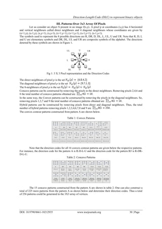
Direction-Length Code (DLC) To Represent Binary Objects
Dr G D Jasmin, M G Justin Raj
Assistant Professor Institute of Aeronautical Engineering Telangana Dundigal, Hyderabad
Assistant Professor Annai Vailankanni College of Engineering Pottalkulam, K K Dist Tamil Nadu
Abstract: More and more images have been generated in digital form around the world. Efficient way of
description and classification of objects is a well needed application to identify the objects present in images.
Shape is an important visual feature of an image. Searching for images using shape features has also attracted
much attention. In this paper the Direction-Length Code which is also called a knowledge vector that gives the
information about the direction and length of pixels in every direction in an object is generated to represent
objects. The formal language attempts to simulate the structural and hierarchical nature of the human vision
system. Here, sentences are strings of symbols and languages correspond to pattern class. The patterns over a 3
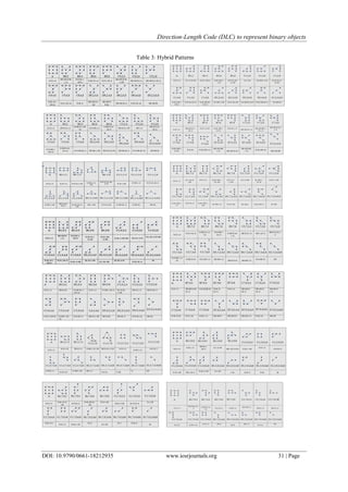
x 3 array of vertices have been generated which form the basic alphabet of the digital picture language. That is,
one can visualize any digital image as a spatial distribution of these patterns. The Direction-Length code (DLC)
compresses the bi-level images by preserving the information at the same time allowing a considerable amount
of data reduction. Furthermore, these codes acts as a standard input format for numerous shape-analysis
algorithms.
I. Introduction
Pattern recognition could be formally defined as categorization of input data into identifiable classes
via extraction of significant features or attributes of the data from the background of irrelevant detail.
The encoding efficiency to represent shapes of objects is very important for image storage and
transmission [1]. It is also important for shape analysis and shape recognition of objects in pattern recognition.
Various methods such as colour based representation, texture based representation, shape based representation
and appearance based representation have been developed to represent objects [2-4]. More studies on these
methods are being carried out and advanced techniques are being developed [5,6]. Shape based representation of
objects gives more clarity about the shape of the objects that acts as a more unique and important feature of
objects for the further identification process [7-9].
II. Object Recognition System
The problem of object recognition is divided into the following sub problems:
1. Image pre-processing
2. Object description
3. Image reconstruction
4. Classification
The input image to the system may be a colour image, a gray scale image or a binary image. The
contours are extracted as they give the outlines of shapes of the objects present in the image. Object description
involves running through the contour pixels and finding a code to represent the object. This involves finding the
length of the contour in every possible direction.
Syntactic pattern recognition is inspired by the phenomenon that composition of a natural scene is an
analogue to the composition of a language, that is, sentences are built up from phrases, phrases are built up from
words and words are built up from alphabets, etc. [10]. The matching between shapes can use string matching
by finding the minimal number of edit operations to convert one string into another. A more general method is
to formulate the representation as a string grammar. Each primitive is interpreted as a alphabet of some
grammar, where a grammar is a set of rules of syntax that govern the generation of sentences formed from
symbols of the alphabet. The set of sentences generated by a grammar G is called its language and is denoted as
L(G). Here, sentences are strings of symbols (which in turn represent patterns), and languages correspond to
pattern class. After grammars have been established, the matching is straightforward. For a sentence
representing an unknown shape, the task is to decide in which language the shape represents a valid sentence.
Syntactic shape analysis is based on the theory of formal language [11]. It attempts to simulate the structural and
hierarchical nature of the human vision system. However, it is not practical in general applications due to the
fact that it is not possible to infer a pattern of grammar which can generate only the valid patterns. In addition,
this method needs a priori knowledge for the database in order to define code words or alphabets.](https://image.slidesharecdn.com/e018212935-160704044338/85/E018212935-1-320.jpg)
![IOSR Journal of Computer Engineering (IOSR-JCE)
e-ISSN: 2278-0661,p-ISSN: 2278-8727, Volume 18, Issue 2, Ver. I (Mar-Apr. 2016), PP 29-35
www.iosrjournals.org
DOI: 10.9790/0661-18212935 www.iosrjournals.org 29 | Page
Direction-Length Code (DLC) To Represent Binary Objects
Dr G D Jasmin, M G Justin Raj
Assistant Professor Institute of Aeronautical Engineering Telangana Dundigal, Hyderabad
Assistant Professor Annai Vailankanni College of Engineering Pottalkulam, K K Dist Tamil Nadu
Abstract: More and more images have been generated in digital form around the world. Efficient way of
description and classification of objects is a well needed application to identify the objects present in images.
Shape is an important visual feature of an image. Searching for images using shape features has also attracted
much attention. In this paper the Direction-Length Code which is also called a knowledge vector that gives the
information about the direction and length of pixels in every direction in an object is generated to represent
objects. The formal language attempts to simulate the structural and hierarchical nature of the human vision
system. Here, sentences are strings of symbols and languages correspond to pattern class. The patterns over a 3
x 3 array of vertices have been generated which form the basic alphabet of the digital picture language. That is,
one can visualize any digital image as a spatial distribution of these patterns. The Direction-Length code (DLC)
compresses the bi-level images by preserving the information at the same time allowing a considerable amount
of data reduction. Furthermore, these codes acts as a standard input format for numerous shape-analysis
algorithms.
I. Introduction
Pattern recognition could be formally defined as categorization of input data into identifiable classes
via extraction of significant features or attributes of the data from the background of irrelevant detail.
The encoding efficiency to represent shapes of objects is very important for image storage and
transmission [1]. It is also important for shape analysis and shape recognition of objects in pattern recognition.
Various methods such as colour based representation, texture based representation, shape based representation
and appearance based representation have been developed to represent objects [2-4]. More studies on these
methods are being carried out and advanced techniques are being developed [5,6]. Shape based representation of
objects gives more clarity about the shape of the objects that acts as a more unique and important feature of
objects for the further identification process [7-9].
II. Object Recognition System
The problem of object recognition is divided into the following sub problems:
1. Image pre-processing
2. Object description
3. Image reconstruction
4. Classification
The input image to the system may be a colour image, a gray scale image or a binary image. The
contours are extracted as they give the outlines of shapes of the objects present in the image. Object description
involves running through the contour pixels and finding a code to represent the object. This involves finding the
length of the contour in every possible direction.
Syntactic pattern recognition is inspired by the phenomenon that composition of a natural scene is an
analogue to the composition of a language, that is, sentences are built up from phrases, phrases are built up from
words and words are built up from alphabets, etc. [10]. The matching between shapes can use string matching
by finding the minimal number of edit operations to convert one string into another. A more general method is
to formulate the representation as a string grammar. Each primitive is interpreted as a alphabet of some
grammar, where a grammar is a set of rules of syntax that govern the generation of sentences formed from
symbols of the alphabet. The set of sentences generated by a grammar G is called its language and is denoted as
L(G). Here, sentences are strings of symbols (which in turn represent patterns), and languages correspond to
pattern class. After grammars have been established, the matching is straightforward. For a sentence
representing an unknown shape, the task is to decide in which language the shape represents a valid sentence.
Syntactic shape analysis is based on the theory of formal language [11]. It attempts to simulate the structural and
hierarchical nature of the human vision system. However, it is not practical in general applications due to the
fact that it is not possible to infer a pattern of grammar which can generate only the valid patterns. In addition,
this method needs a priori knowledge for the database in order to define code words or alphabets.](https://image.slidesharecdn.com/e018212935-160704044338/75/E018212935-1-2048.jpg)
![Direction-Length Code (DLC) to represent binary objects
DOI: 10.9790/0661-18212935 www.iosrjournals.org 35 | Page
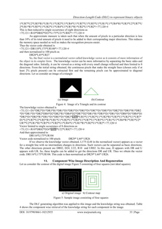
4.
<99,107>/R56*D58*
L56*U57*/<100,107>#
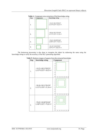
The knowledge base consists of the various components of the image. Large knowledge bases could be
then processed and classified using knowledge manipulation and classification algorithms.
VII. Conclusion
The normalized Direction-Length Code which is also called a knowledge vector that gives the
information of direction and length of pixels in every direction in an object is generated to represent objects. The
reverse process of regeneration of images from the vector code generated is also done. The algorithm shown
good results by generating the same image as its output even when there are more number of components
present.
The Direction-Length code (DLC) that compresses the bi-level images by preserving the information at
the same time allowing a considerable amount of data reduction can act as a standard input format for numerous
shape-analysis and classification algorithms.
References
[1]. H. Freeman, “On the Encoding of Arbitrary Geometric Configurations,” in Proceedings of IRE Translation Elec-tron Computer,
New York, pp-260-268, 1961.
[2]. J.W. Mckee, J.K. Aggarwal, Computer recognition of partial views of curved objects, IEEE Trans. Comput. C-26 790–800 (1977).
[3]. R. Chellappa, R. Bagdazian, Fourier coding of image boundaries, IEEE Trans. Pattern Anal. Mach. Intell. 6 (1) 102–105 (1984).
[4]. C.W. Richard, H. Hemami, “Identi1cation of three dimensional objects using Fourier descriptors of the boundary curve”, IEEE
Trans. System Man Cybernet, SMC-4 (4) 371–378 (1974).
[5]. Torralba, A., Oliva, A., Freeman, W. T., Object recognition by scene alignment [Abstract]. Journal of Vision, 3( 9): 196, 196a
(2003)
[6]. Leordeanu et al., “Beyond local appearance: Category recognition from pair wise interactions of simple features”, IEEE Computer
Society Conference on Computer Vision and Pattern Recognition ( 2007).
[7]. D. Zhang, G. Lu , “Review of shape representation and description techniques”, Pattern Recognition 37 : 1–19 (2004)
[8]. [8] Biederman, I., “Recognition-by-components: A theory of human image understanding”, Psychological Review, 94: 115-147
(1987)
[9]. J. Iivarinen, A. Visa, “Shape recognition of irregular objects”, Intelligent Robots and Computer Vision XV: Algorithms,
Techniques, Active Vision, and Materials Handling, Proc. SPIE 2904 25–32 (1996).
[10]. K.S. Fu, Syntactic Methods in Pattern Recognition, Academic Press, New York, 1974.
[11]. N. Chomsky, Syntactic Structures, Mouton, The Hague, Berlin, 1957.](https://image.slidesharecdn.com/e018212935-160704044338/85/E018212935-7-320.jpg)

This document discusses using a Direction-Length Code (DLC) to represent binary objects. The DLC is a "knowledge vector" that provides information about the direction and length of pixels in every direction of an object. Patterns over a 3x3 pixel array are generated to form a basic alphabet for representing digital images as spatial distributions of these patterns. The DLC compresses bi-level images while preserving shape information and allowing significant data reduction. It can serve as standard input for numerous shape analysis algorithms. Components of images are extracted from the DLC and used to accurately regenerate the original images, demonstrating the effectiveness of the DLC representation.