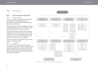
The document summarizes the Dubai Building Code 2021 edition. It includes an introduction to the code and its objectives to unify building design standards in Dubai. The code is organized into different parts covering general regulations, structure, architecture, utilities, accessibility, indoor environment, transportation and more. It references other local regulations and international codes and standards. The hierarchy of these references within the code is also defined.

![Dubai Building Code Part A: General
A 7
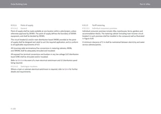
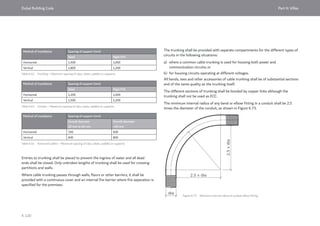
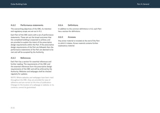
A.4 Relationship of DBC to other local and international regulations
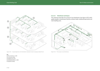
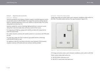
A.4.1 Local regulations
The DBC incorporates, unifies and replaces the
regulations related to building design published
by Dubai Municipality (DM), Dubai Development
Authority (DDA), Department of Planning and
Development – Ports Customs and Freezone
Corporation (Trakhees) and Dubai Silicon Oasis
Authority (DSOA).
Regulations related to building design by Dubai
Electricity and Water Authority (DEWA) and Islamic
Affairs and Charitable Activities Department (IACAD)
are incorporated or cross-referenced by the DBC.
Regulations related to building design by the Security
Industry Regulatory Agency (SIRA) are summarized
and cross-referenced in Part J.
Federal regulations also remain in place. The DBC
follows the Federal regulations of Telecommunications
Regulatory Authority (TRA) and the Ministry of
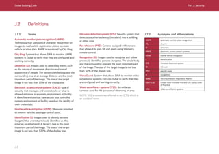
Interior Civil Defence. The TRA regulations are given in
G.11. The UAE Fire and Life Safety Code (UAE FLSC)
[Ref. A.1] is cross-referenced throughout the DBC.
Accessibility requirements of the Dubai Universal
Design Code [Ref. A.2] applicable to building design
are incorporated in Part C and replace these aspects of
the Dubai Universal Design Code.
The Dubai Health Authority (DHA) regulations
[Ref. A.3 and Ref. A.4], along with the relevant Federal
regulations, shall be followed for the design of all
healthcare facilities.
The Department of Tourism and Commerce Marketing
(DTCM) sets out the requirements to achieve star
ratings for hotels, resorts, hotel apartments and
guest houses [Ref. A.5]. Achieving the minimum
requirements of the DBC does not guarantee a rating
from DTCM. DTCM should be consulted at the earliest
stage of design.
The Knowledge and Human Development Authority
(KHDA) and the Ministry of Education both license
education facilities, but they do not provide separate
design requirements. Education facilities are approved
by the main Authorities in accordance with the DBC.
Roads and Transport Authority (RTA) regulations in
relation to the right of way are referenced by the DBC
as appropriate.
Dubai Civil Aviation Authority (DCAA) regulates
maximum building heights within the flight path.
Regulations related to permitting, procedures,
construction and design of non-building elements
such as infrastructure, transportation systems, and
the public realm remain, and can be obtained from, the
relevant Authority.
Planning development regulations published by
Developers or Planning Authorities are not replaced
by the DBC. The DBC contains planning regulations
in Part B, but these shall be followed only where
plot-specific planning development regulations are
unavailable.
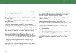
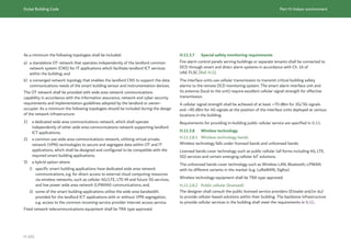
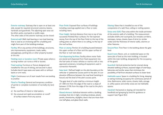
A.4.2 International codes and standards
The DBC relies on international codes and standards,
mainly BS EN and American codes. These codes and
standards shall be used in their latest edition except
where the DBC lists an edition.
NOTE: As an example, Part F (Structures) mandates
the 2016 edition of ASCE/SEI 7.
An edition is mandated in the DBC for one of two
reasons.
a) The DBC refers to sections, tables and figures
within that version of the international code or
standard and therefore the cross-references might
not apply to later editions.
b) The edition has been reviewed for its applicability
to Dubai.](https://image.slidesharecdn.com/dubaibuildingcodeenglish2021editionak-231227052107-72adb61a/85/Dubai-Building-Code_English_2021-Edition_AK-pdf-9-320.jpg)
![Dubai Building Code Part A: General
A 8
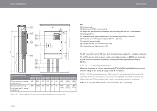
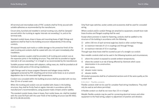
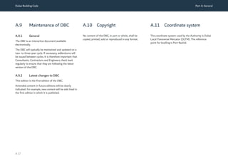
A.4.3 Hierarchy of codes and standards
The hierarchy of the adopted codes and standards is
defined as follows.
a) The DBC and UAE Fire and Life Safety Code of
Practice (UAE FLSC) [Ref. A.1] together form the
main regulations for building design in Dubai. The
UAE FLSC is referenced throughout the DBC.
b) The DBC follows the SIRA regulations for
the design of security. These regulations are
summarized and referenced in Part J.
c) The DBC follows the Federal regulations of TRA
for the design of telecommunications. These
regulations are documented in G.11.
d) The international codes and standards for design,
material and product specification listed under the
heading of “Essential references” in each Part, and
referenced in the relevant sections of each Part, are
also requirements of the DBC.
e) Documents listed under the heading of “Further
reading” in each Part are provided for information
as useful guides to building design.
Where there is conflict between the DBC and reference
model codes or standards, the most restrictive/highest
performance requirements shall be met.
Where there is a conflict between a general
requirement and a specific requirement of the DBC
or its referenced codes/standards then the specific
requirement applies.
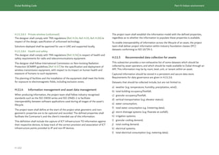
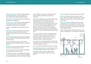
A.4.4 Safe by design
The principle of “safe by design” requires the
Consultant to address the health and safety of all
occupants, Contractors and users of the building.
This includes Contractors, maintenance staff,
occupants, visitors and demolition teams throughout
the building lifecycle.
This process is documented in a risk register where
the Consultant acknowledges the risk, investigates
mitigation measures and provides a design solution
which reduces the risk to a practicable level, while also
taking account of cost, constructability, other project
goals, etc.
Safe by design principles are not mandated by the
first edition of the DBC, but are likely to be enforced
in future revisions. Consultants should familiarize
themselves with these principles by reference to the
Construction Design and Management Regulations
[Ref. A.7].](https://image.slidesharecdn.com/dubaibuildingcodeenglish2021editionak-231227052107-72adb61a/85/Dubai-Building-Code_English_2021-Edition_AK-pdf-10-320.jpg)
![Dubai Building Code Part A: General
A 9
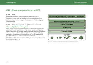
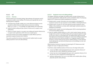
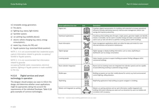
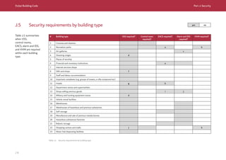
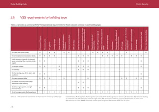
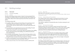
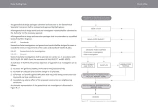
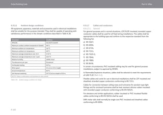
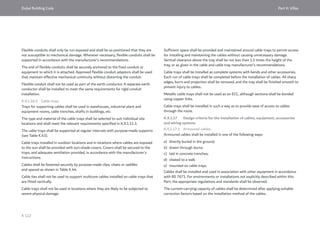
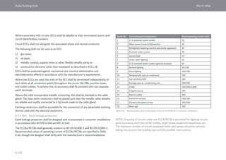
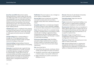
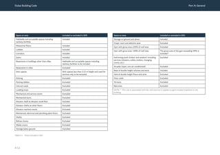
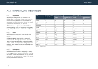
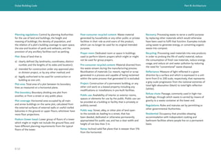
A.5 Scope and application of the DBC
A.5.1 General
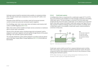
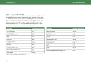
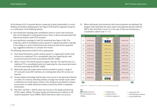
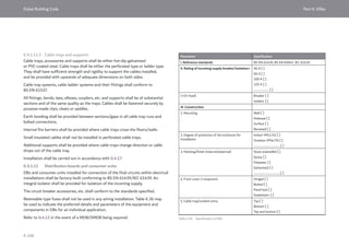
The DBC applies to new buildings and changes to existing buildings as described in
Table A.1, except where an alternative solution is permitted (see A.8).
Change to an
existing building
Description Applicable codes
Renovation Change to linings/finishes or
strengthening of structure. It does not
involve any reconfiguration of internal
spaces.
DBC and UAE FLSC [Ref. A.1] apply
to interior finish changes or building
envelope changes.
Modification Fit-out of a space/unit, or change to a
service system or building element.
DBC and UAE FLSC [Ref. A.1] apply to
the fit-out or change.
Reconstruction Modification that is not stand-alone.
It affects adjacent egress routes
or systems that are not part of the
reconstruction area such that a larger
part of the building might need to
be closed down or not occupied for a
period of time.
DBC and UAE FLSC [Ref. A.1] apply
to the reconstruction and any areas of
the building which are impacted by the
reconstruction.
Change of use Change of use or occupancy of part or
all of the building.
DBC and UAE FLSC [Ref. A.1] apply
to the change of use and any areas of
the building which are impacted by the
change of use, e.g. existing exit stairs
and routes, vertical transport, quantity
and type of sanitary provisions.
Addition An increase in the building’s gross area
or built-up area, and/or height or depth.
DBC and UAE FLSC [Ref. A.1] apply to
the addition.
If the addition relies on the remainder of
the existing building for escape, vertical
transport, etc., the existing building
shall also be assessed against the DBC
and UAE FLSC [Ref. A.1].
Occupancy Use
Assembly Amusement park, theatre, cinema, restaurant, museum, art gallery, place of
worship, library, exhibition and conference centre, etc.
Business Office, professional services, government centre, post office, bank, etc.
Educational University, college, school, kindergarten, nursery, educational institute
Hotel establishment Hotel, resort, guesthouse, hotel apartment
Residential Apartment, studio, student accommodation, labour accommodation, staff
accommodation
Villas and townhouses
Parking Open, enclosed, mechanical
Retail Shopping centre, department store, shop, kiosk, showroom, stores
Mall Open mall, enclosed mall
Industrial Factory, workshop
Storage Warehouse
Table A.1 Existing building and application of the DBC
Table A.2 Occupancies and use types
The DBC applies to the occupancies and use types described in Table A.2.](https://image.slidesharecdn.com/dubaibuildingcodeenglish2021editionak-231227052107-72adb61a/85/Dubai-Building-Code_English_2021-Edition_AK-pdf-11-320.jpg)
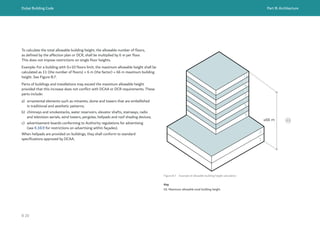
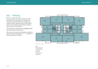
![Dubai Building Code Part A: General
A 13
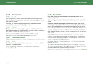
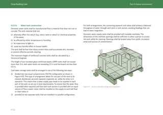
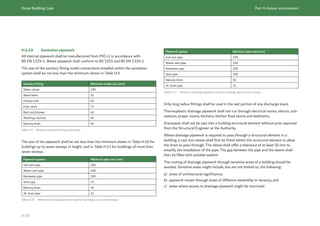
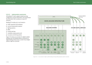
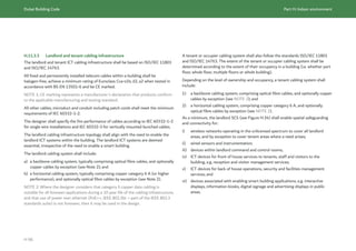
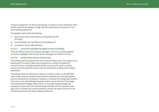
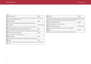
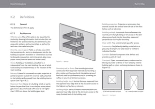
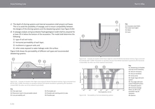
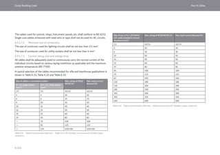
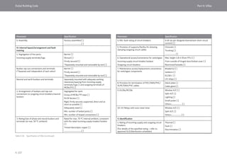
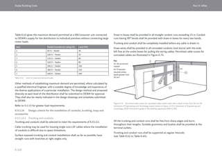
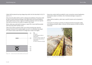
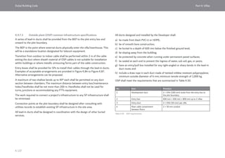
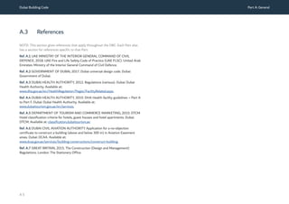
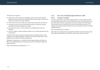
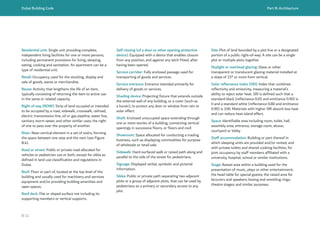
A.5.2.3 Gross area and net area
The terms “gross area” (GA) and “net area” (NA) are
used by the DBC to calculate occupant load in a floor
or space. They are defined in A.2 and further described
and illustrated in Part B.
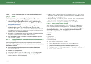
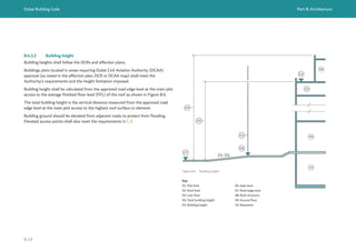
A.5.2.4 Building height
Building height is a key variable that is checked by
the Authorities for compliance with the DBC, DCR/
affection plans, UAE FLSC [Ref. A.1] and, where
applicable, DCAA restrictions on building heights
located in Aviation easement areas due to overhead
flight paths.
Each definition of building height is slightly different
as they are used to regulate different issues. For this
reason, Consultants shall check building height against
the DBC, DCR/affection plans, UAE FLSC [Ref. A.1]
and, where applicable, DCAA regulations [Ref. A.6].](https://image.slidesharecdn.com/dubaibuildingcodeenglish2021editionak-231227052107-72adb61a/85/Dubai-Building-Code_English_2021-Edition_AK-pdf-15-320.jpg)
![Dubai Building Code Part A: General
A 14
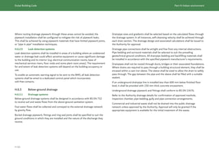
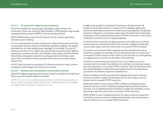
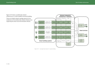
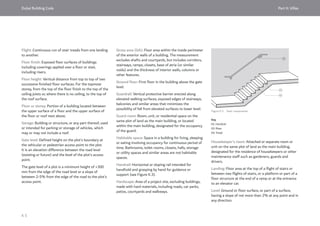
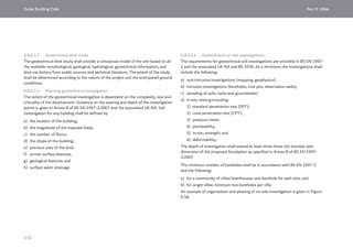
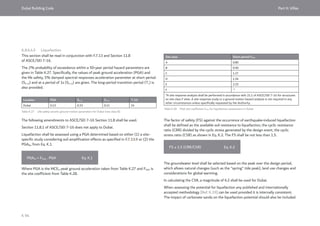
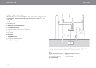
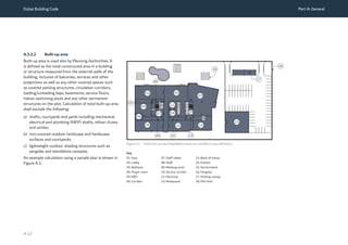
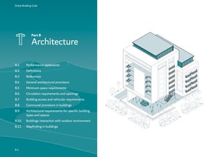
A.6 Navigating the DBC
A.6.1 Division into Parts
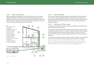
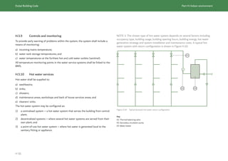
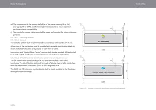
The DBC is divided into Parts as described in Figure A.2.
Each Part is subdivided into sections by topic.
Minimum requirements for sustainability are embedded
within the relevant Parts of the DBC. Developers and
Consultants are encouraged to apply the rating system
adopted by the relevant Authority to assess their
projects and exceed these minimum requirements.
Fire safety requirements are given in the relevant
Parts of the DBC and cross referenced to UAE FLSC
[Ref. A.1]. The aim of this cross-referencing is to help
Consultants navigate and coordinate the requirements
of the two documents. Where an element of UAE FLSC
is not applicable in Dubai, or the DBC contains additional
information not in UAE FLSC, this is indicated in the
text.
Figure A.2 How to use and navigate the DBC
Part H
Indoor environment
Part E
Building envelope
Part J
Security
Part B
Architecture
Part C
Accessibility
Part K
Villas
Part F
Structure
Part D
Vertical transportation
Part G
Incoming utilities](https://image.slidesharecdn.com/dubaibuildingcodeenglish2021editionak-231227052107-72adb61a/85/Dubai-Building-Code_English_2021-Edition_AK-pdf-16-320.jpg)
![Dubai Building Code Part A: General
A 16
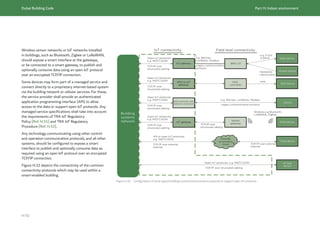
A.7 Adoption of DBC
Projects in design or construction that have a final
approved design from the Authority do not need to
conform to the DBC.
Projects in design without a final approved design shall
conform to the DBC. The requirements of the DBC are
based on regulations enforced prior to its publication
and in many instances the DBC is less stringent. For
example, requirements unrelated to health, safety,
welfare and environment have generally been removed
from the regulations. Therefore, it is expected that
there will be benefits to Developers and Owners in
adopting the DBC.
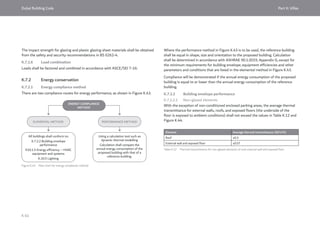
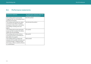
A.8 Alternative solutions
The DBC is intended to be a prescriptive design code.
Performance statements are provided at the start of
each Part to describe the outcomes that the completed
building is expected to achieve.
The performance statements form a set of overarching
regulations that convey the requirements of the
DBC (see A.6.2).
The preferred method of meeting the performance
statements of the DBC is to follow the prescriptive
design requirements in each Part.
The inclusion of performance statements sets out the
intent of the DBC and future-proofs it, supporting
a possible transition to a more performance-based
regulatory system in the future.
Alternative solutions which meet the performance
statements of the DBC are permitted:
a) for projects that cannot reasonably meet the
prescribed requirements; and
b) for changes to existing buildings where the
requirements of the DBC would result in a
disproportionate cost to the Owner/Developer.
The Authority will decide if an alternative solution is
permitted.
An alternative solution shall meet the intent of
the performance statements and provide at least
an equivalent level of performance to all of the
prescriptive design requirements.
Alternative solutions shall be applied to a performance-
based design holistically such that a change from
one Part of the DBC does not reduce the building’s
performance in other aspects.
Alternative solutions for changes to existing buildings
shall demonstrate that the existing conditions are
maintained to the current level of compliance or
improved to meet the safety levels of the DBC and
UAE FLSC [Ref. A.1].
The Authority will decide whether or not a
performance-based design is equivalent to the
prescriptive design requirements. The responsibility
is on the Consultant to demonstrate that the
performance-based design is required and that
it is at least equivalent to the prescriptive design
requirements.
The DBC lists preferred international codes and
standards in each Part (see A.4.2). Where permitted
by the Authority, alternative standards can be used
provided that the comparable standard meets the
intent of the DBC.](https://image.slidesharecdn.com/dubaibuildingcodeenglish2021editionak-231227052107-72adb61a/85/Dubai-Building-Code_English_2021-Edition_AK-pdf-18-320.jpg)
![Dubai Building Code Part B: Architecture
B 7
Hardscape: Area of a project site, excluding buildings,
made with hard materials, including roads, car parks,
patios, courtyards and walkways.
Hazardous waste: Waste material that can cause
substantial harm to humans, properties and/
or the environment due to its inherent hazardous
characteristics. Hazardous waste takes the form of
solid, liquid, sludge, gas or any combination thereof.
Healthcare: Occupancy used to provide medical,
psychiatric, surgical, therapeutic treatment for people.
Helipad: Dedicated structural surface used for the
landing, taking off, taxiing and parking of helicopters.
High-rise building: Building height greater than or
equal to 23 m and up to 90 m, measured in accordance
with the UAE FLSC [Ref. B.1]. A more detailed
definition is given in UAE FLSC.
Hospital: Building or portion thereof used on a 24 h
basis for the medical, psychiatric, obstetrical or surgical
care of four or more inpatients.
Hotel: Building or groups of buildings under the
same management in which there are sleeping
accommodations for lodging with or without meals for
people on a transient basis.
Hotel apartments: Collection of apartments or studios
that are rented to guests by the day, the week, the
month or the year.
Hotel establishment: Hotels, guest houses, hotel
apartments or resorts.
Hotel suite: Separate guest unit in a hotel that
contains one or more bedrooms with a living room and
other services.
Housekeeper’s room: Attached or separate room or
unit on the same plot of land as the main building,
designated for the residence of housekeepers or other
maintenance staff such as gardeners, guards and
drivers.
Hybrid vehicle: Vehicle using two different forms
of power, such as an electric motor and an internal
combustion engine, or an electric motor with a battery
and fuel cells for energy storage.
Illuminance: Amount of light falling onto a surface area.
Industrial/factory/workshop: Occupancy in which
products are manufactured or in which processing,
assembling, mixing, packaging, finishing, decorating, or
repair operations are conducted.
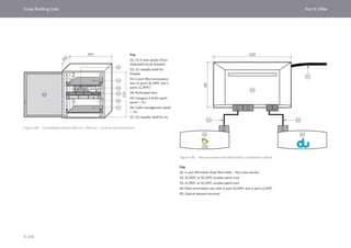
01
02
03
04
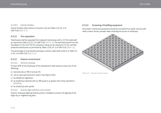
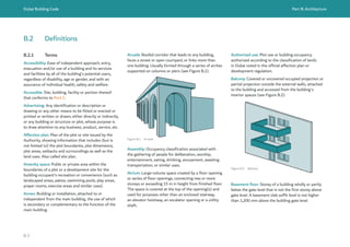
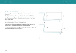
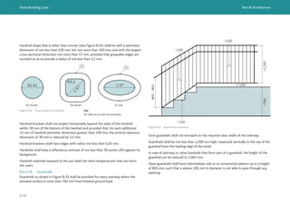
Figure B.4 Stair components
Key
01: Handrail
02: Tactile surface
03: Tread
04: Riser](https://image.slidesharecdn.com/dubaibuildingcodeenglish2021editionak-231227052107-72adb61a/85/Dubai-Building-Code_English_2021-Edition_AK-pdf-27-320.jpg)
![Dubai Building Code Part B: Architecture
B 8
Intersection: Crossing of two or more roads.
Kiosk: Temporary or permanent structure of
lightweight construction occupied as a retail outlet,
food outlet or service outlet. Kiosks are generally
located at malls, shopping centres, assembly areas and
exhibition centres.
Kitchen: Place for the preparation of meals and
beverages.
Labour accommodation: Building used for group
accommodation for workers of a company or a firm,
for which the sanitary facilities and other services are
common.
Landing: Floor area at the top of a flight of stairs or
between two flights of stairs, or a platform or part of a
floor structure at the end of a ramp or at the entrance
to an elevator car.
Land use: Activities, operations, or purposes that are
employed in a particular geographic area; the specific
manner in which a plot of land is utilized. Land use
is usually regulated through zoning and planning
regulations.
Level: Ground or floor surface, or part of a surface,
having a slope of not more than 2% at any point and in
any direction.
Line of sight: Imaginary line from the eye to a
perceived object or view.
Loading area: Area used for loading or unloading
of vehicles, located entirely on private property and
provided with permanent independent access.
Lobby: Entrance or foyer to a space or building which
acts as a transition area.
Local road: A roadway with the primary function
of providing access to adjacent properties and to
roadways of a higher functional classification.
Local species: Local plants and plants adapted to the
local environment.
Low-rise building: Building height less than or up to
15 m, measured in accordance with the UAE FLSC
[Ref. B.1]. A more detailed definition is given in
UAE FLSC.
Low-depth underground building: Building up to 7 m
below or having up to two basements below the level of
exit discharge, measured in accordance with the UAE
FLSC [Ref. B.1]. A more detailed definition is given in
UAE FLSC.
Main building: Building used for the main or prime
functional use within the plot.
Mall: Pedestrian area within a building that serves as
access for multiple tenants with levels that are open to
each other. A covered mall has an enclosed or roofed
common pedestrian way. An open mall has an unroofed
common pedestrian way.
Massing: Overall mass or size of a building or project,
its physical volume or magnitude.
Masterplan: Comprehensive plan to guide the long-
term physical development of a specific area based
on identified objectives, strategies, and timelines
for implementation. Includes plans for land use,
community facilities and utilities, transportation of
goods and people, and energy use and conservation.
Zoning ordinances and policies are developed for
different areas or zoning districts based on the
masterplan.
Means of egress: Continuous and unobstructed route
from any point in a building or structure to a public
way.
Mechanical parking: Parking areas employing parking
machines, lifts, elevators or other mechanical devices
for vehicles moving from and to street level. Public
occupancy is prohibited above street level.
Mezzanine floor: Intermediate level or levels between
the floor and ceiling of any storey equal to or less than
one-third of the floor it is contained in. A partial floor
greater than one-third of the floor it is contained in is a
floor, not a mezzanine.
Mid-rise building: Building height greater than 15 m
but less than 23 m, measured in accordance with the
UAE FLSC [Ref. B.1]. A more detailed definition is
given in UAE FLSC.
Mixed use building: Building or structure containing
two or more occupancies.](https://image.slidesharecdn.com/dubaibuildingcodeenglish2021editionak-231227052107-72adb61a/85/Dubai-Building-Code_English_2021-Edition_AK-pdf-28-320.jpg)
![Dubai Building Code Part B: Architecture
B 12
Stair: Change in elevation, consisting of one or more
risers.
Staircase: Space inside the building within which the
stairs are erected.
Stairway: One or more flights of stairs, either
exterior or interior, with necessary landings and
platforms connecting them to form a continuous and
uninterrupted passage from one level to another.
Structure: Constructed, erected material or
combination of materials which requires being located
on the ground or attached to something located on the
ground.
Student accommodation: Building or part thereof
in which sleeping units are provided for occupancy
by university, school or other educational institute’s
students and which is regulated by such institution.
Studio: Independent residential unit with combined
living room and bedroom and space provision for food
preparation and sanitation.
Super high-rise building: Building height greater than
90 m, measured in accordance with the UAE FLSC
[Ref. B.1]. A more detailed definition is given in
UAE FLSC.
Swimming pool: Constructed pool for swimming,
bathing or wading whether above or below the ground
surface regardless of depth or water surface area.
Tandem parking: Two or more parking bays with one of
the spaces placed behind the other.
Terrace: Covered or uncovered platform or roof,
protected by a guardrail or parapet wall and supported
by the structure of the floor below.
Toilet stall: Cubicle within a public toilet constructed
with demountable partitions or walls surrounding a
water closet.
Tread: Stepping space in a stair flight to set the foot
(see Figure B.4).
Vehicle access: Roadway, usually paved, intended to
provide ingress and egress of vehicular traffic from a
public right-of-way to a building entrance or parking
area.
Vehicle barrier: Component or system of components,
near open sides of a parking floor or ramp or building
walls that act as restraints for vehicles.
Warehouse: Occupancy used primarily for the storage
or sheltering of goods, merchandise, products, or
vehicles.
Waste: Unwanted or unusable materials which are
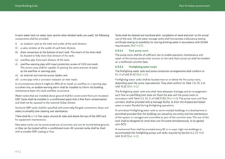
discarded after their primary use.
Waste room: Room dedicated for the purpose of
holding, prior to disposal, waste generated in the
building. This room can be located within the plot limits
or within building enclosure, subject to the approval of
Authorities.
Waste segregation: Separation or sorting of waste
materials into their respective fractions, such as the
separation of recyclables.
Water closet: Toilet bowl and its attached accessories.
Wayfinding: System of providing appropriate
information to assist a person to pass through the built
environment towards a specific destination. Wayfinding
includes orienting oneself, knowing one’s destination,
following the best route, recognizing one’s destination
and finding one’s way back out.
Wind towers: Shelter with 50% of its area open to the
sky usually constructed to enhance the architectural
beauty of a building or to suit a certain climate need.](https://image.slidesharecdn.com/dubaibuildingcodeenglish2021editionak-231227052107-72adb61a/85/Dubai-Building-Code_English_2021-Edition_AK-pdf-32-320.jpg)
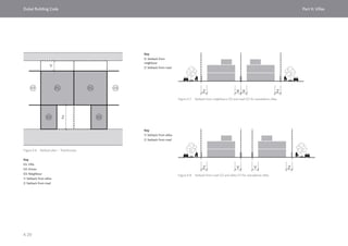
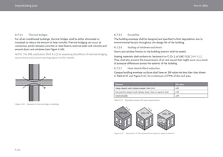
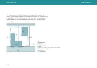
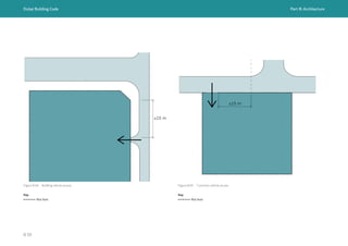
![Dubai Building Code Part B: Architecture
B 22
Setbacks are shown in plan view in Figure B.10.
Setbacks shall also allow for fire separation between
buildings and fire truck access routes. To prevent
external fire spread, the building, shall be physically
separated from adjacent plots/buildings or external
walls and openings of the building shall be fire
resistance rated (see Sections 2.7 and 2.8, Ch. 1 of
UAE FLSC [Ref. B.1]).
Fire truck access shall be provided between buildings
and around buildings as required by Ch. 2 of UAE
FLSC [Ref. B.1]. This vehicle access might need to be
accommodated within the plot limits.
Where high-rise and super high-rise buildings (as
defined by UAE FLSC [Ref. B.1]) are built on a podium
and the distance from fire truck accessway to the
façade of the high-rise/super high-rise exceeds 30 m,
fire truck access to the podium shall be provided as
required by Section 2.8, Ch. 2 of UAE FLSC [Ref. B.1].
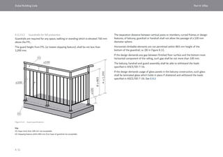
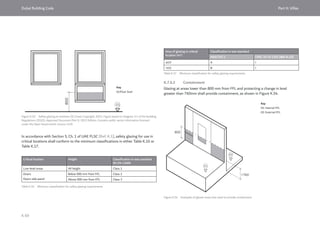
Setbacks from sikkas shall be calculated from the
centre of the sikka (see Figure B.11). When the sikka
width is more than 6 m, the maximum applicable width
from the centre of the sikka is 3 m. If the building
setback from the plot limit is found to be 1.5 m or less,
no setback is required.
Plots neighbouring cemeteries shall provide a minimum
setback of 3 m.
Plots adjacent to metro stations or metro
infrastructure shall conform to the RTA railway
protection code for the emirate of Dubai [Ref. B.2].
X
Y
X
02
01
02
03
04
Figure B.10 Setback plan
Key
01: Building footprint
02: Neighbour
03: Allowable projection
04: Road
X: Setback from neighbour (see Table B.1)
Y: Setback from centre of sikka
Plot limit
Setback line
Figure B.11 Setback from sikka
Key
01: Plot
Y: Setback from centre of sikka
Plot limit
Y Y
01 01](https://image.slidesharecdn.com/dubaibuildingcodeenglish2021editionak-231227052107-72adb61a/85/Dubai-Building-Code_English_2021-Edition_AK-pdf-42-320.jpg)
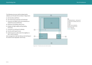
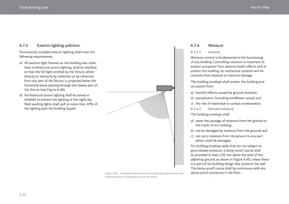
![Dubai Building Code Part B: Architecture
B 27
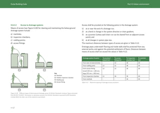
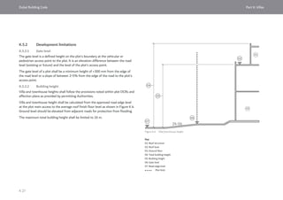
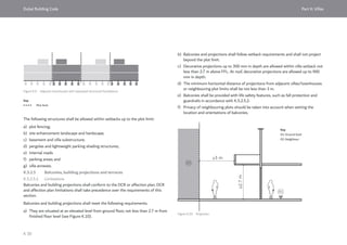
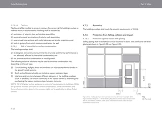
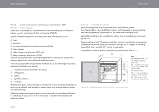
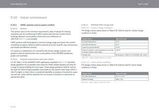
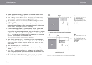
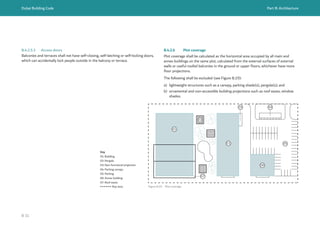
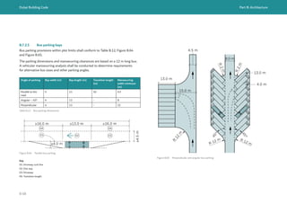
B.4.2.5 Balconies, building projections and terraces
B.4.2.5.1 Limitations
A balcony, building projection or terrace (see Figure B.16 and Figure B.17) can be
provided along the whole or part of the building façade constructed on the side of
the plot that overlooks a road or neighbours. Balconies, building projections and
terraces shall meet the following requirements and limitations.
a) The affection plan or DCR shall take precedence over the provisions in this
subclause.
b) A balcony or projecting building element shall be situated at an elevated level
from ground floor, not less than 3 m from FFL of sidewalks and footpaths as
shown in Figure B.16.
c) Projections from vehicle roads shall be set back a minimum of 0.6 m from
the edge of vehicle road, or a height clearance of not less than 5.5 m shall be
maintained from road level as shown in Figure B.16.
d) Projections above fire truck accessways shall be not less than 4.5 m in height from
road level in accordance with Section 2, Ch. 2 of UAE FLSC [Ref. B.1].
e) Projections outside the plot boundary are permitted on the road-facing side when
the width of road in which the balcony or projection protrudes exceeds 9 m.
f) Balconies and building projections shall be limited to 10% of the facing street
width beyond the plot limit and 1.8 m maximum projection into the ROW as
shown in Figure B.16.
g) The minimum horizontal distance of balconies and building projections from other
adjacent buildings, structures or neighbouring plots shall maintain the minimum
required setback (see Figure B.17).
Plots adjacent to metro stations or metro infrastructure shall conform to the RTA
railway protection code for the emirate of Dubai [Ref. B.2].
Privacy of neighbouring plots should be taken into account when setting the location
and orientation of balconies.
A privacy partition shall be provided between connected balconies of different
residential units.](https://image.slidesharecdn.com/dubaibuildingcodeenglish2021editionak-231227052107-72adb61a/85/Dubai-Building-Code_English_2021-Edition_AK-pdf-47-320.jpg)
![Dubai Building Code Part B: Architecture
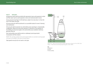
B 32
B
B
A
A
Figure B.20 Building exit separation
Key
A: Building diagonal distance
B: Direct distance between exit doors
NOTE:
B = 1/3 A for sprinklerled buildings
B = 1/2 A for unsprinklered buildings
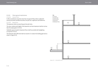
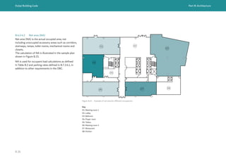
B.4.3 Building floors general requirements
B.4.3.1 Ground floor
Ground floor use allowance shall conform to planning regulations. A building
or facility may have more than one ground floor where a split-level entrance
has been provided and where a building plot has significant level difference.
The ground floor shall be connected to the adjacent public ways by lobbies.
The number and location of exits discharging directly from the building to outside
shall conform to Section 3.10, Ch. 3 of UAE FLSC [Ref. B.1]. The points of exit
discharge shall be separated from each other on plan by one third (sprinklered
buildings) or one half (unsprinklered buildings) of the largest measurements
of the building diagonal distance (see Figure B.20).
An emergency command centre conforming to Table 1.9, Ch. 1 and Section 2.9,
Ch. 2 of UAE FLSC [Ref. B.1] shall be provided in malls, amusement park, high-rise
and super high-rise buildings. The emergency command centre may be shared with
a security room, rest area or control room, provided that it meets emergency
command centre specifications.
The emergency command centre shall be at ground floor and separated from the
remainder of the building by a 1 h fire barrier constructed in accordance with Ch. 1
of UAE FLSC [Ref. B.1]. The entrance to the emergency command centre shall
be on the exterior of the building along the fire accessway or if this is not feasible,
at the main entrance lobby of the building. Emergency command centres shall meet
the minimum room sizes specified in B.5.2.](https://image.slidesharecdn.com/dubaibuildingcodeenglish2021editionak-231227052107-72adb61a/85/Dubai-Building-Code_English_2021-Edition_AK-pdf-52-320.jpg)
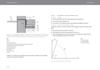
![Dubai Building Code Part B: Architecture
B 33
≤1.2
m
01
02
03
04
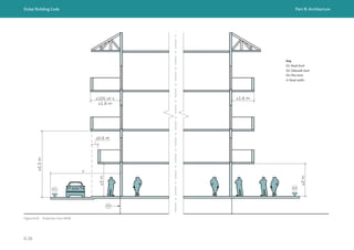
Figure B.21 Basement height from gate level
Key
01: Upper floor
02: Ground floor
03: Basement floor
04: Gate level
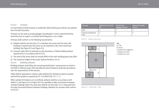
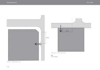
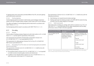
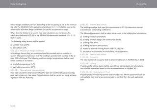
B.4.3.2 Basements
The space use shall conform to planning regulations.
Basement floors shall not extend beyond the plot limits.
The basement shall be connected to the building by means of vertical circulation
(staircases/elevators) in accordance with Ch. 1 to Ch. 10 of UAE FLSC [Ref. B.1].
The basement slab soffit level shall not extend 1.2 m above the building gate level as
shown in Figure B.21.
B.4.3.3 Podium
Building podiums shall conform to planning regulations.
When podium floors are used for habitable and occupiable spaces, these spaces
shall be designed as indoor spaces with building envelope, acoustic treatment
and ventilation/thermal comfort as required by Part E and Part H.](https://image.slidesharecdn.com/dubaibuildingcodeenglish2021editionak-231227052107-72adb61a/85/Dubai-Building-Code_English_2021-Edition_AK-pdf-53-320.jpg)
![Dubai Building Code Part B: Architecture
B 36
Occupancy Use Occupant load factor
(m2
per person unless
otherwise stated)
Area used for
calculation
Retail Retail shops 5.6 GA
Department stores,
multi-level retail
3.7 GA
Floors used for goods
not accessed by public
27.9 GA
Mall Mall – less than
14,000 m2
in area
2.8 Gross leasable area in
accordance with UAE
FLSC [Ref. B.1]
Mall – more than
14,000 m2
in area
3.3 Gross leasable area in
accordance with UAE
FLSC [Ref. B.1]
Industrial Factories 9.3 GA
Storage Warehouse 27.9 GA
Educational Classrooms 1.9 Net area
Laboratories, vocational 4.6 Net area
Residential Accommodation,
shared sleeping spaces
5.0 Net area
Labour accommodation
– sleeping spaces
3.7 Net area
Healthcare Refer to DHA
regulations and
guidelines [Ref. B.3 to
Ref. B.18]
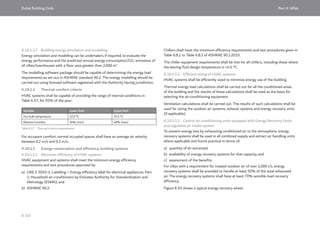
The occupant load factors in Table B.2 generally align with UAE FLSC [Ref. B.1] with
the exception of residential. However, exit widths and number of exits from a room,
space, floor and building shall be calculated using the occupant load factors in Table
3.13, Ch. 3 of UAE FLSC [Ref. B.1].
Any space or building not listed in Table B.2 above shall conform to the occupant load
factors noted in Table 3.13, Ch. 3 of UAE FLSC [Ref. B.1].
Table B.2 Occupant load factor per person (continued)](https://image.slidesharecdn.com/dubaibuildingcodeenglish2021editionak-231227052107-72adb61a/85/Dubai-Building-Code_English_2021-Edition_AK-pdf-56-320.jpg)
![Dubai Building Code Part B: Architecture
B 37
Occupancy/use Minimum area (m2
) Minimum dimension – length
and width of a room (m)
Residential living space
(bedroom, living room)
10.5 3 (See Figure B.23)
Residential studio (including
bathroom and kitchen space)
21 3
Housekeeper’s/guard rooms
(single occupancy only exclusive
of toilet area)
4.5 2.1
Retail shop — 2.4
Retail showroom — 9
Enclosed office — 2.4
Enclosed kitchen 5.4 1.8
Bathroom and toilets Shall meet fixture clearances noted in B.8.1.5
Toilet stalls Shall conform to B.8.1.4
Hotel establishment Refer to applicable DTCM classification criteria
[Ref. B.19 to Ref. B.36]
Healthcare facilities Refer to DHA regulations and guidelines [Ref. B.3 to Ref. B.18]
Fire pump rooms Refer to Table 1.9, Ch. 1 of UAE FLSC [Ref. B.1] for minimum room
sizes dependent upon equipment selected and other requirements
such as proximity to exit stairways.
Emergency command centre 19 3
Table B.3 Minimum room sizes
≥3.0 m
≥3.0
m
A ≥ 10.5 m2
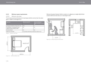
Figure B.23 Minimum residential living space dimensions
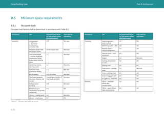
B.5.2 Minimum room sizes
The net area and clear dimension of a room/space shall be not less than the
minimum sizes given in Table B.3. Minimum sizes for some other occupancies are
given in B.9.
Key
A: Room area](https://image.slidesharecdn.com/dubaibuildingcodeenglish2021editionak-231227052107-72adb61a/85/Dubai-Building-Code_English_2021-Edition_AK-pdf-57-320.jpg)
![Dubai Building Code Part B: Architecture
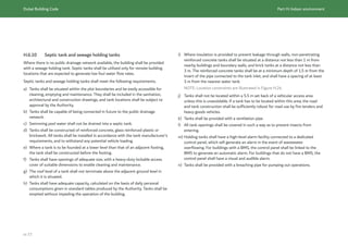
B 38
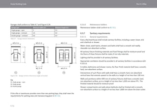
The manoeuvring space between kitchen counters or adjacent to a single-sided
kitchen counter shall be not less than 1.2 m, as shown in Figure B.24.
Figure B.24 Manoeuvring space within kitchen
≥1.2 m
≥1.2 m
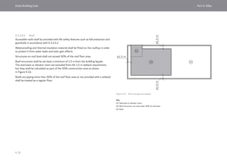
B.5.3 Minimum clear heights
The clear height of a space shall be not less than the minimum values given in
Table B.4.
The clear heights shall be calculated from FFL to any structural suspended element
or ceiling soffits, as shown in Figure B.25.
Occupancy Use Minimum clear heights (m)
Assembly Awqat mosque prayer hall 3.8
Jumaa mosque prayer hall 5.0
Prayer rooms 2.7
Ballrooms, multipurpose assembly halls 2.7
Business Offices 2.5
Retail, mall Retail shops/stores, showrooms 2.5
Educational Schools, nurseries and kindergartens –
classrooms
2.7
Healthcare — Refer to DHA regulations and
guidelines [Ref. B.3 to Ref. B.18]
Residential,
hotel
Living and bedroom spaces 2.7
Table B.4 Minimum clear heights](https://image.slidesharecdn.com/dubaibuildingcodeenglish2021editionak-231227052107-72adb61a/85/Dubai-Building-Code_English_2021-Edition_AK-pdf-58-320.jpg)
![Dubai Building Code Part B: Architecture
B 39
Occupancy Use Minimum clear heights (m)
Industrial Industrial equipment areas Minimum headroom for industrial
equipment access shall conform to
Table 3.4, Ch. 3 of UAE FLSC [Ref. B.1].
Common
areas
Parking – for light vehicles 2.3
Corridors, passageways and elevator lobbies 2.3
Occupiable spaces (other than listed above) 2.3
Washrooms and toilets 2.3
Storage and utility space 2.3
Stairways 2.03 m above the stair treads and
2.3 m above the stair landings
(see B.6.4.1.15)
Means of egress 2.3
In not more than 50% of the ceiling
area, protruding objects may extend
below the minimum clear ceiling height,
where a minimum headroom of 2.03 m
from FFL shall be provided.
Fire pump room 2.5 (see Table 1.9, Ch. 1 of UAE FLSC
[Ref. B.1])
Figure B.25 Clear heights
>
2.7
m
>
2.3
m
Table B.4 Minimum clear heights (continued)](https://image.slidesharecdn.com/dubaibuildingcodeenglish2021editionak-231227052107-72adb61a/85/Dubai-Building-Code_English_2021-Edition_AK-pdf-59-320.jpg)
![Dubai Building Code Part B: Architecture
B 40
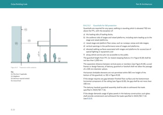
B.6 Circulation requirements and openings
B.6.1 Walking surfaces
All walking surfaces, including accessible routes, shall
conform to the requirements of C.5 & C.7.2.
Changes in level in means of egress of more than 13
mm, but not more than 535 mm, shall be achieved
either by a ramp conforming to C.5.9.1 or by a stair
conforming to B.6.4.1.
B.6.2 Corridors
B.6.2.1 Minimum clear widths
The clear width of corridors shall be not less than
the values given in Table B.5. Where a corridor forms
part of an accessible route, it shall also meet the
requirements specified in C.5.
Occupancy/use Minimum clear corridor width (m)
Assembly, other public use buildings 1.5 for single loaded corridors
1.8 for double loaded corridors
Residential (common corridor) 1.5 for single sided residential units
1.8 for double sided residential units
(See Figure B.26 as example for corridor arrangement
in residential building)
Retail 1.8
Mall and retail areas > 3,600 m2
GA per
floor (pedestrian way)
6 for double sided units
3 for single sided units
Healthcare Refer to Dubai Health Authority’s (DHA) regulation and guidelines [Ref. B.3 to Ref. B.18] for
specific requirements and UAE FLSC [Ref. B.1]
Educational 2.1 for single sided classroom
3 for double sided classroom
Business – Offices 1.5 for single loaded corridors
1.8 for double loaded corridors
Hotel establishment
(common corridor)
1.5 for single loaded corridors
1.8 for double loaded corridors
Refer to DTCM classification criteria [Ref. B.19 to Ref. B.36]
for specific requirements.
Internal corridors inside residential and
hotel apartment units
1.0
(See Figure B.26 as example for corridor arrangement in residential building)
Service corridors 1.2
Corridors in all buildings Section 5, Ch. 3 of UAE FLSC [Ref. B.1] mandates minimum clear corridor widths per
occupancy type.
Exit passageways If applicable, Table 3.8, Ch. 3 of UAE FLSC [Ref. B.1] mandates minimum clear exit passageway
widths.
Table B.5 Minimum clear corridor widths
NOTE: Retail units under a single roof or not fire separated and having a ground floor GA of more than 3,600 m2
, irrespective of the number of storeys,
are treated as a mall in accordance with Ch.1 of the UAE FLSC [Ref. B.1].](https://image.slidesharecdn.com/dubaibuildingcodeenglish2021editionak-231227052107-72adb61a/85/Dubai-Building-Code_English_2021-Edition_AK-pdf-60-320.jpg)
![Dubai Building Code Part B: Architecture
B 42
B.6.2.2 Fire resistance rating
Exit access corridors shall be 1 h fire resistance rated when required by Table 1.11a,
Ch. 1 of UAE FLSC [Ref. B.1].
Exit passageways shall achieve the fire resistance rating and construction
requirements of Table 3.8, Ch. 3 of UAE FLSC [Ref. B.1].
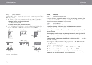
B.6.2.3 Kiosks in mall pedestrian ways
Kiosks are allowed along a mall pedestrian way under the following conditions
prescribed by Table 1.9, Ch. 1 of UAE FLSC [Ref. B.1].
a) The minimum corridor width between the kiosks and the adjacent shop or
construction shall be 3 m as shown in Figure B.27.
b) The minimum horizontal separation distance between 2 adjacent kiosks shall be
not less than 6 m.
c) The maximum area of a single kiosks or group of kiosks shall be 18 m2
collectively,
or 28 m2
in an open mall.
d) Kiosks shall conform to the fire safety system provisions and construction
materials required of Table 1.9 and Section 7.1.40, Ch. 1 of UAE FLSC [Ref. B.1].
B.6.3 Elevator lobbies
Elevator lobby design shall conform to Part D.
Figure B.27 Kiosk provision within malls
Key
01: Kiosk
02: Adjacent construction
03: Corridor width
≥6
m
≥3 m ≥3 m
01
01
01
02
03 03
02](https://image.slidesharecdn.com/dubaibuildingcodeenglish2021editionak-231227052107-72adb61a/85/Dubai-Building-Code_English_2021-Edition_AK-pdf-62-320.jpg)
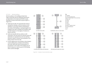
![Dubai Building Code Part B: Architecture
B 43
B.6.4 Vertical circulation in buildings
B.6.4.1 Stairways
B.6.4.1.1 General
The minimum number of exit stairways, stairway width, stairway separation,
exit discharge arrangements and fire resistance rating of the staircase shall
be determined in accordance with Ch. 3 of UAE FLSC [Ref. B.1].
The architectural requirements of a stairway design in this subsection align with
or exceed UAE FLSC [Ref. B.1].
At least one protected exit stairway shall extend to all roofs.
B.6.4.1.2 Exit staircase construction
Exit stairways shall be enclosed in fire resistance rated reinforced concrete (RCC)
staircase construction when required by Table 3.4, Ch. 3 of UAE FLSC [Ref. B.1],
except staircases serving low-rise buildings or low-depth underground buildings
where 2 h fire resistance rated blockwork construction is permitted.
RCC staircases with separate cores but a common RCC divider are acceptable only
in low-rise and mid-rise buildings, provided that the whole staircase conforms
to building construction type and separation distance between exits.
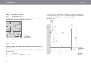
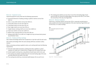
B.6.4.1.3 Stairway width
All stairways shall have a clear width of not less than 1,200 mm. The minimum width
of an exit stair shall be determined in accordance with Section 4, Ch. 3 of UAE FLSC
[Ref. B.1] depending upon the number of occupants it serves.
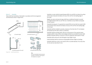
The required width of a stairway shall be measured from wall to the clear available
width of the step (see Figure B.28). The maximum projections of handrails allowed
in this required width is 100 mm on each side, at a height of 865 mm to 965 mm
(see Figure B.28).
> 1,200
≤100
865-965
1,065
01
02
03
04
05
06
07
Figure B.28 Handrail encroachment
Key
01: Handrail
02: Dual guardrail
03: Wall
04: Handrail height
05: Tread
06: Open side
07: Stair](https://image.slidesharecdn.com/dubaibuildingcodeenglish2021editionak-231227052107-72adb61a/85/Dubai-Building-Code_English_2021-Edition_AK-pdf-63-320.jpg)
![Dubai Building Code Part B: Architecture
B 49
Figure B.36 Example stair signage
NO ACCESS TO ROOF
7
DOWN TO GROUND FLOOR
FOR EXIT DISCHARGE
WING A اﻟﺟﮭﺔ
FLOOR اﻟطﺎﺑﻖ
اﻟﺳطﺢ ﻋﻠﻰ ﻣﺧرج ﯾوﺟد ﻻ
اﻹﺧﻼء أﺟل ﻣن اﻷرﺿﻲ اﻟطﺎﺑﻖ اﻟﻰ اﻟﮭروب
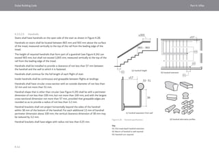
The triangular openings formed by the riser, tread, and bottom element of a guardrail
at the open side of a stair shall be of such size that a sphere 150 mm in diameter
is not able to pass through the triangular opening.
Guardrails at landings or balconies over stairways shall also conform to B.4.2.5.2.
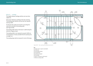
All staircases shall include signage indicating the floor level, wing of the building (if
applicable), and direction of egress (see Figure B.36).
Signage shall be in English and Arabic and shall conform to B.11.4.5.
Signage shall be provided inside the staircase at floor landings. It is not required on
mid-landings and shall not be located on door leaves. It shall be clearly visible for stair
users, located at a height of not less than 1,220 mm from the floor landing to the
bottom of the sign. The top of the signage shall be located not more than
2,135 mm above the floor landing.
Lettering shall be not less than 25 mm high.
B.6.4.1.10 Exterior stairways
An open outside exit stair shall not be provided in any building at more than 15 m
from finished ground level.
Outside stairs more than 11 m above the finished ground level, shall be provided
with an opaque visual obstruction not less than 1,200 mm in height.
Outside stairs shall be separated from the interior of the building by construction
with the required fire resistance rating in accordance with Table 3.4, Ch. 3 of
UAE FLSC [Ref. B.1].
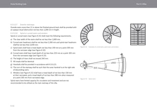
B.6.4.1.11 Scissor or interlocking stairs
In accordance with Ch. 3 of the UAE FLSC [Ref. B.1], interlocking or scissor stairways
(see Figure B.37) shall be counted as a single exit. As such, the two interlocking
sections of a scissor staircase (see Figure B.38) are not required to be separated by
fire resisting construction.
02
01
01
01 02
02
Figure B.37 Scissor stairways in plan
Key
01: Section 1
02: Section 2](https://image.slidesharecdn.com/dubaibuildingcodeenglish2021editionak-231227052107-72adb61a/85/Dubai-Building-Code_English_2021-Edition_AK-pdf-69-320.jpg)
![Dubai Building Code Part B: Architecture
B 52
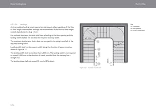
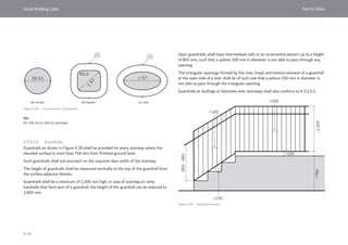
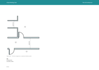
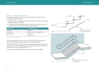
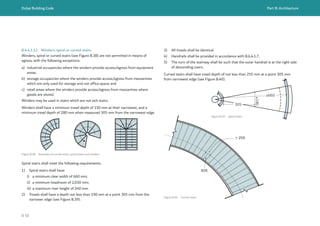
B.6.4.1.16 Examples of compliant stair arrangements
The stairway designs in Figure B.42 are deemed to be compliant with B.6.4.1 for the
following reasons.
a) They have regular flights and consistent dimensions of steps.
b) There is a direct exit at discharge level from under the stair flight.
c) Where two doors on opposite sides are provided, each door swing does not
obstruct more than half of the required landing width.
Straight run stairs are acceptable, provided that the height between landings is not
more than 3,660 mm.
B.6.4.2 Ramps
Pedestrian ramps in buildings shall conform to C.5.9.
Guardrails shall conform to B.6.4.1.8. Handrails shall conform to C.5 or B.6.4.1.7. as
applicable.
Materials of construction and fire resistance of ramps shall conform to Section 3.7,
Ch. 3 of UAE FLSC [Ref. B.1].
B.6.4.3 Elevators
Elevators and vertical transportation systems shall conform to Part D.
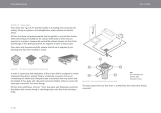
Figure B.42 Examples of compliant stair treads, flights and arrangements](https://image.slidesharecdn.com/dubaibuildingcodeenglish2021editionak-231227052107-72adb61a/85/Dubai-Building-Code_English_2021-Edition_AK-pdf-72-320.jpg)
![Dubai Building Code Part B: Architecture
B 53
≥915
01
02
Figure B.43 Minimum door clear width
Key
01: Door clear width
02: Door
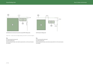
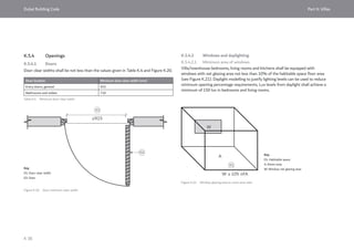
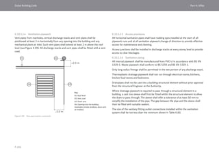
B.6.5 Building openings
B.6.5.1 Doors
The door clear width shall be not less than the minimum values given in Table B.7 and
Figure B.43.
Figure B.44 Clearances between two adjacent doors.
≥1.2
m
The clear distance between two doors openings shall be not less than 1.2 m, as
shown in Figure B.44.
Accessible door requirements are given in C.5.8.
The design of doors as exits shall conform to the applicable requirements of Section
3.2, Ch. 3 of UAE FLSC [Ref. B.1] depending upon the location and purpose of the
door, including:
Door location Minimum door clear width (mm)
Entry doors, general 915
Bathrooms and toilets (excluding toilet stalls) 815
Exit doors, exit access doors 915 or greater depending upon the occupant load
served, as specified in Section 3, Ch. 3 of UAE
FLSC [Ref. B.1]
Table B.7 Minimum door clear width
a) direction of door swing;
b) limitations on when a particular door
type (side hinged, powered, sliding,
revolving, turnstile) can be used;
c) door hardware;
d) encroachment of the door swing into
corridors/stairs;
e) fire resistance rating; and
f) security arrangement.](https://image.slidesharecdn.com/dubaibuildingcodeenglish2021editionak-231227052107-72adb61a/85/Dubai-Building-Code_English_2021-Edition_AK-pdf-73-320.jpg)
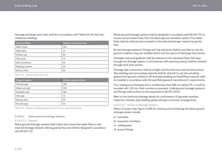
![Dubai Building Code Part B: Architecture
B 54
Table B.8 Minimum percentage of window to floor area
Occupancy Use Minimum window glazing area
(percentage of window net glazing
area to room area)
Business Offices – workstation areas 10%
Residential and hotel Living, bedroom spaces (excluding
kitchen area)
10%
Educational Schools, nurseries and kindergartens
– classrooms
10%
Assembly Mosques 10%
Figure B.45 Window glazing area to room area ratio
A
W
W ≥ 10% ofA
01
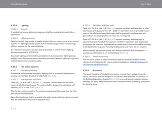
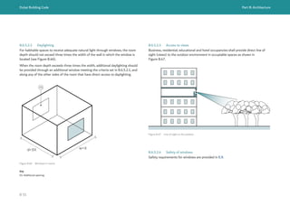
B.6.5.2 Windows and daylighting
B.6.5.2.1 Minimum area of windows
Daylighting provisions for habitable and occupiable spaces shall conform to Table B.8
and Figure B.45. Housekeeper's rooms shall be provided with adequate daylighting
similar to living spaces as shown in Table B.8 and Figure B.45.
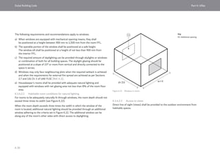
The following requirements and recommendations apply to windows.
a) When windows are equipped with mechanical opening means, this shall be
positioned at a height between 900 mm to 1,200 mm from the room FFL.
Window latches for non-accessible spaces can be positioned higher than 1,200
mm.
b) Operable portion of the window shall be positioned at a safe height and equipped
by means of fall protection, according to E.9.4.
c) The required amount of daylighting can be provided through skylights or windows
or combination of both for all building spaces. The skylight glazing should be
positioned at a slope of 15° or more from vertical and directly connected to the
space it serves.
d) Windows may only face neighbouring plots when the required setback is achieved
and when the requirements for external fire spread are achieved as per Sections
2.7 and 2.8, Ch. 1 of UAE FLSC [Ref. B.1].
Daylighting modelling to justify lightling levels can be used to reduce minimum
opening percentage requirements, provided that minimum lux levels are achieved. Lux
levels from daylight shall achieve a minimum of 150 lux in bedrooms and living rooms.
Key
01: Room
A: Room area
W: Window net glazing area](https://image.slidesharecdn.com/dubaibuildingcodeenglish2021editionak-231227052107-72adb61a/85/Dubai-Building-Code_English_2021-Edition_AK-pdf-74-320.jpg)
![Dubai Building Code Part B: Architecture
B 56
B.6.6 Openings between floors
B.6.6.1 Convenience openings and communicating spaces
Convenience openings and communicating spaces are described in Table 1.9, Ch. 1 of
UAE FLSC [Ref. B.1].
Convenience openings for escalators and stairs shall conform to the fire safety
requirements given in Table 1.9, Ch. 1 of UAE FLSC [Ref. B.1] depending upon
whether or not the building is required to be sprinkler protected.
Floor voids forming a communicating space of maximum 3 floors shall conform to
the fire safety requirements of Table 1.9, Ch. 1 of UAE FLSC [Ref. B.1] depending
upon whether or not the building is required to be sprinkler protected.
B.6.6.2 Atria
In most cases, an atrium shall be separated from the rest of the building by 1 h fire
resisting construction, as required by Table 1.9, Ch. 1 of UAE FLSC [Ref. B.1].
This does not apply if an engineered smoke control system is provided, in accordance
with Section 2.7, Ch. 10 of UAE FLSC [Ref. B.1].
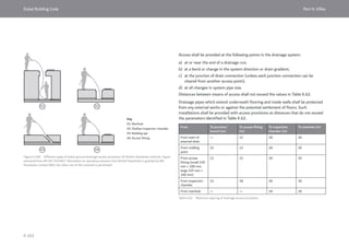
B.6.6.3 Courtyards
Courtyards provided through buildings to give light to habitable or occupable spaces
may be located anywhere within the height of a building.
Courtyards shall be a maximum of 23 m high, measured from the base of the
courtyard to the opening at the top of the courtyard, and achieve a minimum of
6 m x 6 m in plan (see Figure B.48 where "h" is the height of the courtyard).
Buildings with courtyards greater than 15 m high, measured from the base of the
courtyard to the opening at the top of the courtyard, shall be fully sprinkler protected
in accordance with Ch. 9 of UAE FLSC [Ref. B.1].
≥6 m
≥6 m ≥6 m
≥6
m
h
Figure B.48 Courtyard dimensions](https://image.slidesharecdn.com/dubaibuildingcodeenglish2021editionak-231227052107-72adb61a/85/Dubai-Building-Code_English_2021-Edition_AK-pdf-76-320.jpg)
![Dubai Building Code Part B: Architecture
B 57
Courtyards with in plan dimensions less than 6 m x 6 m are not permitted unless the
enclosing walls of the courtyard achieve the same fire resistance rating as the floor
through which they pass, as required by Table 1.9, Ch. 1 and Table 10.2, Ch. 10 of
UAE FLSC [Ref. B.1].
Courtyards may be shaded or covered by a light weight or translucent roofing system,
provided that it is 50% perforate.
B.6.6.4 Shafts
Shafts passing through multiple floors for the passage of MEP services, elevator
hoistways and stairs shall achieve the same fire resistance rating as the floor through
which they pass, as required by Table 1.9, Ch. 1 and Table 10.2, Ch. 10 of
UAE FLSC [Ref. B.1].
Shafts provided through buildings to give light to habitable or occupiable spaces
remote from an external wall are not permitted unless the fire resistance rating of
UAE FLSC [Ref. B.1] is achieved. This means that the shaft construction shall be
fire resistance rated, and any window assemblies in the shaft shall be permanently
closed and fire resistance rated in accordance with the fire testing and certification
requirements given in Table 1.18, Ch 1 of UAE FLSC [Ref. B.1].
Glazed elevators contained entirely within an atrium or communicating space do not
need to be fire resistance rated.](https://image.slidesharecdn.com/dubaibuildingcodeenglish2021editionak-231227052107-72adb61a/85/Dubai-Building-Code_English_2021-Edition_AK-pdf-77-320.jpg)
![Dubai Building Code Part B: Architecture
B 58
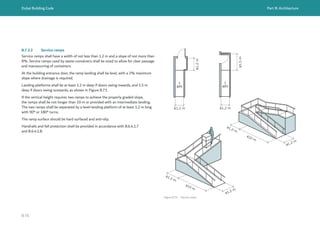
B.7 Building access and vehicular requirements
B.7.1 Building access
The following provisions shall be included when setting the building access strategy
during the design process.
a) Public and service entrances shall be clearly located and identified with signage
as in accordance with B.11. The location of car parking and the main entrance
shall be clearly identified with signage in accordance with B.11.
b) Buildings shall allow for smooth pedestrian access with crossings and pathways.
Pathways shall be provided for building entries from surrounding streets, parking
bays and external sidewalk.
c) Accessible routes shall be provided in accordance with C.5.
d) Buildings providing pick-up and drop-off areas shall conform to Chapter 7.2
of Dubai access management manual requirements [Ref. B.37].
e) For mixed-use buildings containing residential occupancy and other public
or business occupancies, the residential pedestrian access point and lobbies shall
be separated from those serving public/business occupancies. For other mixed-
use buildings, the segregation of pedestrian access points for different building
occupancies is recommended for privacy and security.
f) The number and location of exits discharging directly from the building to outside
shall be in accordance with B.4.3.1.
g) Access routes and accessways for fire trucks shall be provided in accordance
with Ch. 2 of UAE FLSC [Ref. B.1]. Fire trucks shall be able to reach, within the
required distances and as applicable, the building entry points, breeching inlets
and the perimeter façade of the building.
h) Public roadways carrying heavy volumes of traffic shall not be used for access
unless an alternative access point cannot be provided, and it is agreed with RTA
and the Authority.
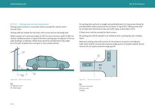
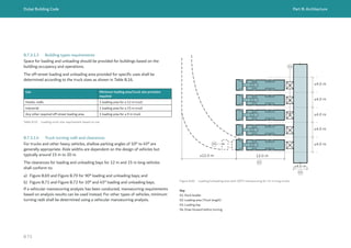
B.7.2 Vehicle access and movement
B.7.2.1 General requirements
Vehicle access shall be located away from any traffic intersections depending on road
type, vehicle type and other factors as approved by RTA.
Vehicle access shall conform to RTA requirements. Public rights of way shall be
designed in accordance with the RTA Dubai access management manual [Ref. B.37]
and RTA Geometric design manual for Dubai roads [Ref. B.38].
Building developments which are deemed by the Authority to have an impact on the
traffic generation for the surrounding roads and properties shall submit a traffic
impact assessment (TIA) or traffic impact study (TIS) to the Authorities.
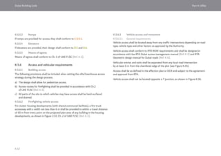
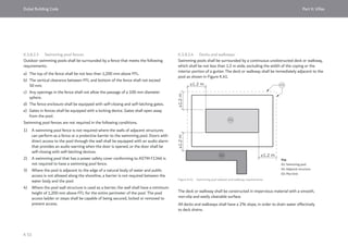
Vehicle access shall be separated from local road intersection or minor T junctions by
not less than 15 m from the chamfered edge of the plot (see Figure B.49 and
Figure B.50). For other road intersections, Dubai access management manual
requirements [Ref. B.37] shall be followed.
If the building is facing more than one road, the vehicle access point should be from
the secondary road, or as specified on the affection plan, as shown in Figure B.49.
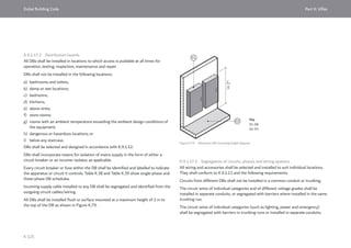
Segregation between light and heavy vehicle parking areas inside plots shall
be provided in accordance with B.7.3.
Vehicle access shall not be located opposite a T junction, as shown in Figure B.50.](https://image.slidesharecdn.com/dubaibuildingcodeenglish2021editionak-231227052107-72adb61a/85/Dubai-Building-Code_English_2021-Edition_AK-pdf-78-320.jpg)
![Dubai Building Code Part B: Architecture
B 60
Internal roads within plot limits shall be not less than:
a) 3 m clear width road or pavement for one-way traffic;
b) 6 m clear width road or pavement for two-way traffic.
All vehicular roadways and parking areas shall be provided with exterior lighting to
illuminate the surface area in accordance with H.7. All internal roads or access to
plots shall be lit to a CIE 115 (lighting class M5, Lav ≥ 0.5 cd/m2
with uniformity
U0 ≥ 0.35) [Ref. B.39]. Lighting shall be designed, arranged and installed to confine
direct rays onto the plots and to direct light away from adjacent structures or streets.
All parts of the site to which vehicles might have access shall be hard surfaced and
drained.
All vehicular manoeuvring to take place within plot limits without impacting ROW
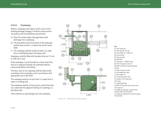
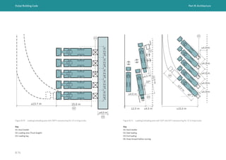
B.7.2.2 Vehicular ramps
Ramps allocated for vehicular access shall conform to Table B.9 and the following.
a) Curved and helical vehicular ramps are not preferred.
b) Any curved portion of vehicular ramps shall conform to the requirements for
curved ramps.
c) Lane separation for ramps shall be provided through curbs, walls or other
structural segregation.
d) Where a curb is used between lanes to separate traffic flows, each lane shall meet
the minimum width requirement. Curbs shall be not less than 300 mm in width,
and not less than 150 mm in height.
Ramp type Maximum slope
percentage
Minimum single
lane width (m)
Minimum inner
circle radius (m)
Minimum vertical
clear height above
any point (m)
Straight
See Figure B.51
12% 3 - 2.4
Curved
See Figure B.52
12% 3.5 4 2.4
Helical
See Figure B.53
8% 5 6 2.4
Table B.9 Ramp slope and width
Figure B.51 Straight ramp
Key
01: Curb or structure
02: Lane separation
≥
3.0
m
≥3.0
m
01
02
01](https://image.slidesharecdn.com/dubaibuildingcodeenglish2021editionak-231227052107-72adb61a/85/Dubai-Building-Code_English_2021-Edition_AK-pdf-80-320.jpg)
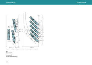
![Dubai Building Code Part B: Architecture
B 61
Figure B.52 Curved ramp
≥
3
.
5
m
≥
3
.
5
m
≥
4
.
0
m
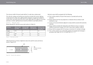
Vehicular ramps shall meet the following requirements.
1) Floor surfaces shall be of broom finish texture or provided with anti-slip
treatment.
2) Ramps shall be free from any projections or obstacles that could obstruct safe
movement or use.
3) Corners of structural elements adjacent to ramps shall be covered with
protective materials.
4) Ramps shall be provided with reflective mirrors that are appropriately sized
to enhance visibility at directional changes, turns and in areas where visibility
is difficult.
5) Ramps shall be equipped with all necessary connections for rainwater drainage.
6) Floor surfaces shall be non-combustible, graded and equipped with drainage
in accordance with Table 3.37, Ch. 3 of UAE FLSC [Ref. B.1].
Vehicular ramps shall not be used for means of egress, as specified in Table 3.37,
Ch. 3 of UAE FLSC [Ref. B.1], with the following exception. For one level below
or one level above discharge level of parking, vehicular ramps may be used as one of
the means of egress, provided that no shutters or doors are installed in such ramps.
Figure B.53 Helical ramp
< 8%](https://image.slidesharecdn.com/dubaibuildingcodeenglish2021editionak-231227052107-72adb61a/85/Dubai-Building-Code_English_2021-Edition_AK-pdf-81-320.jpg)
![Dubai Building Code Part B: Architecture
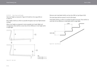
B 62
Ramp design should provide blended transitions to horizontal parking levels.
The transition should be equal to half the percentage of ramp’s slope, according
to the dimensions given in Table B.10 and Figure B.54.
Ramp slope, *R Transition slope, *T Transition length, *L
(minimum) (m)
12% 6% 3.6
10% 5% 3
8% 4% 2.4
Table B.10 Transition and ramp slopes recommendations
Figure B.54 Vehicle ramp slope transition
*T
*T
*L
*L
*R
≥2.4
m
≥2.4
m
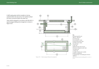
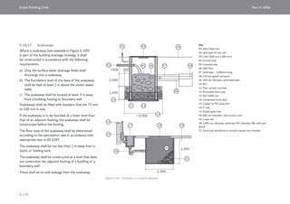
Mechanical parking can substitute for vehicular ramps, provided that following
requirements are met.
i) A TIA shall be submitted.
ii) The system used shall be provided with an inspection certificate for installation
and safety in accordance with BS EN 14010:2003+A1:2009.
iii) Building occupants shall not be able to access the structure. A suitable and
airconditioned waiting area shall be provided adjacent to the parking exits.
iv) An emergency auto response system shall be provided, to enable continuity
of use and avoid impact on ROW and traffic flow in the event of system failure.
v) The system shall be capable of operating at 25% minimum capacity through
a standby generator in case of electrical outage.
vi) The net floor height of the parking levels shall match the system specification
requirements, and may be less than the minimum clear heights given in B.5.3.
vii) The mechanical parking shall meet the fire safety requirements of
UAE FLSC [Ref. B.1].](https://image.slidesharecdn.com/dubaibuildingcodeenglish2021editionak-231227052107-72adb61a/85/Dubai-Building-Code_English_2021-Edition_AK-pdf-82-320.jpg)
![Dubai Building Code Part B: Architecture
B 63
Figure B.55 Parking at slope
≤4% ≤4%
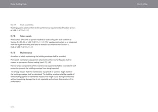
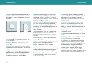
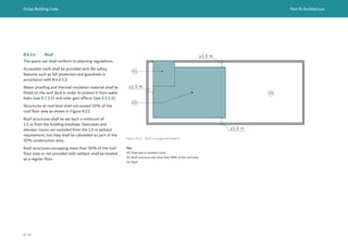
B.7.2.3 Parking floors and structures
B.7.2.3.1 General
Parking areas within a building shall be separated from other occupancies.
Occupiable spaces adjacent to or within parking areas shall be provided with
thermal and acoustic treatment. Ventilation separation conforming to Part H,
and fire separation conforming to Table 1.9, Ch. 1 of UAE FLSC [Ref. B.1], shall be
provided.
Parking areas clear height shall conform to B.5.3.
Floor surfaces shall be non-absorbent, non-combustible, graded and equipped
with drainage in accordance with Table 3.37, Ch. 3 of UAE FLSC [Ref. B.1].
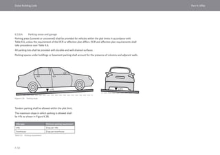
The area of floor used for parking of cars or other vehicles shall be sloped to facilitate
the movement of liquids to a drain or toward the main vehicle entry doorway.
The slope in areas where vehicles are parked shall be not more than 4% (as shown
in Figure B.55). Accessible parking slopes shall be limited to a maximum of 2%.
Vehicle guards not less than 1,200 mm in height shall be placed where the vertical
distance from the floor of a drive lane or parking bay to the ground or surface directly
below is greater than 300 mm, such as parking on podiums roof or adjacent to ramps.
The guards shall conform to Clause 4.5.3 of ASCE/SEI 7-16. Mechanical parking
facilities are exempt from this requirement.
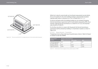
B.7.2.3.2 Open versus enclosed parking
Open parking has permanent wall openings for natural ventilation at each parking
level. The exterior sides of the structure shall have uniformly distributed openings
on two or more sides. The area of such openings in external walls on a level shall
be not less than 20% of the total perimeter wall area of each level. The aggregate
length (i.e. total of widths) of the openings deemed to be providing natural
ventilation shall be not less than 40% of the perimeter of the level. Open parking
facilities shall conform to NFPA 88A for natural ventilation.
Parking facilities that do not meet the definition of open parking shall be designed
as enclosed parking with mechanical ventilation as required by H.4.12.11.](https://image.slidesharecdn.com/dubaibuildingcodeenglish2021editionak-231227052107-72adb61a/85/Dubai-Building-Code_English_2021-Edition_AK-pdf-83-320.jpg)

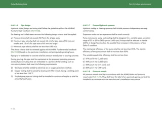
![Dubai Building Code Part B: Architecture
B 70
Occupancy Use Parking ratio
Hotel
establishment
Hotel – Standard room 1 bay for every 5 rooms
Hotel – Suite room 1 bay for every 2 suites
Hotel apartment 1 bay for every 1 apartment up to 150 m2
2 bays for every 1 apartment above
150 m2
Hotel food and beverage, management
office, retail
1 bay for every 50 m2
of related space NA
Hotel meeting, ballroom, function hall 1 bay for every 20 m2
of related space NA
Healthcare Refer to DHA guidelines, Part B [Ref. B.3
to Ref. B.18]
Healthcare centres 1 bay per each patient bed
1 bay per each 50 m2
of NA for internal
clinics, staff offices and all occupiable
spaces
Industrial Light medium industry 1 bay for every 70 m2
of management
office NA
Heavy industry 1 bay for every 70 m2
for office if area
exceeds 10%
Warehouse 1 bay for every 70 m2
of management
office NA
Parking ratios for any building occupancy not listed in Table B.13 should
be determined in accordance with RTA parking rates requirements [Ref. B.40].
When the building includes a mix of occupancies, the parking provided should
conform to the requirement for each specific occupancy.
Parking for sport stadiums and event arenas shall be determined according
to a transport study of the type of sport or event, the number of seats, visitors
and the public parking and transportation network.
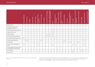
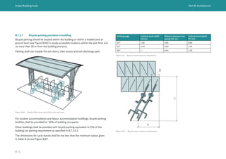
B.7.2.6.2 Preferred parking
For buildings that have more than 20 parking bays, designated preferred parking
shall be provided for a combination of hybrid vehicles, electrical vehicles and carpool
vehicles.
The number of preferred parking bays shall be calculated based on the total
vehicle parking bays required for the building, as defined in B.7.2.6.1.
The percentage required for preferred parking is 5%. This percentage does
not include parking bays provided for people of determination (see C.6.4).
B.7.2.6.3 Charging equipment for electrical vehicles in malls
For shopping malls, where preferred parking bays are provided in accordance with
B.7.2.6.2, necessary charging equipment for electrical vehicles shall be provided for
20% of the total preferred parking bays. Charging equipment shall conform to G.5.
Table B.13 Parking ratios (continued)](https://image.slidesharecdn.com/dubaibuildingcodeenglish2021editionak-231227052107-72adb61a/85/Dubai-Building-Code_English_2021-Edition_AK-pdf-90-320.jpg)
![Dubai Building Code Part B: Architecture
B 78
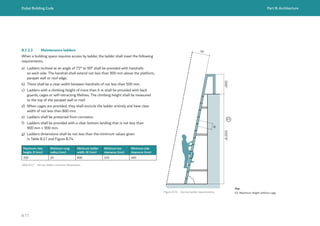
Ladders are permitted to provide access to the following areas only:
1) spaces frequented by personnel for maintenance, repair or monitoring
of equipment;
2) non-occupiable spaces accessed only by catwalks and crawl spaces;
3) raised areas used primarily for purposes of security, life safety or fire safety
including, but not limited to, observation galleries, prison guard towers, fire
lookout towers or lifeguard stands; and
4) non-occupied roofs that are not required to have stairway access.
B.7.3.4 Access to utilities
UAE FLSC [Ref. B.1] does not permit ladder access in lieu of stairs to roofs, to
liquefied petroleum gas (LPG) tanks on roofs, solar power generation systems on
roofs or fire pump rooms.
At least one RCC protected exit stairway shall extend to all roofs.
At least one RCC protected exit stairway shall reach the level of an LPG tank
installation. Cat ladders, alternate stairs and temporary stairs are not permitted
(see Ch. 11 of UAE FLSC [Ref. B.1]).
Solar power generation systems on roofs shall be accessed by one RCC protected exit
stairway in accordance with Ch. 14 of UAE FLSC [Ref. B.1].
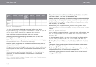
A fire pump room shall be in the basements or the ground floor, within 6 m visibility
of a protected exit stair leading to ground floor in accordance with Table 1.9, Ch. 1
of UAE FLSC [Ref. B.1]. Hatch entry, cat ladders, spiral stairs, winding stairs are not
allowed to access the fire pump room.](https://image.slidesharecdn.com/dubaibuildingcodeenglish2021editionak-231227052107-72adb61a/85/Dubai-Building-Code_English_2021-Edition_AK-pdf-98-320.jpg)
![Dubai Building Code Part B: Architecture
B 80
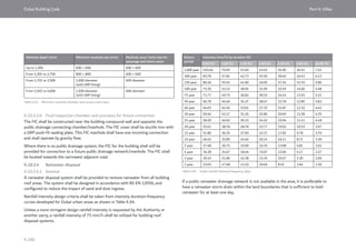
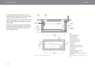
Occupancy Use Water closets Washbasins
Male Female Male Female
Assembly Restaurant, dining areas 1 per 75 for the first 300
occupants
1 per 200 occupants for the
remainder exceeding 300
1 per 50 for the first 200
occupants
1 per 75 occupants for the
remainder exceeding 200
1 per 75 for the first 300
occupants
1 per 200 occupants for the
remainder exceeding 300
1 per 50 for the first 200
occupants
1 per 75 occupants for the
remainder exceeding 200
Ball rooms, multipurpose assembly
hall, exhibition hall, production studios,
art gallery, museums, exercise rooms,
fitness centres, waiting areas
1 per 125 occupants 1 per 65 occupants 1 per 125 occupants 1 per 65 occupants
Fixed seating spaces (cinemas, theatres
and similar).
Conference room, meeting rooms,
library – reading area
1 per 125 occupants 1 per 65 occupants 1 per 125 occupants 1 per 65 occupants
Amusement parks, indoor play areas,
skating rinks
1 per 75 occupants for the first
1,500
1 per 120 occupants for the
remainder exceeding 1,500
1 per 40 occupants for the first
1,600
1 per 60 occupants for the
remainder exceeding 1,600
1 per 120 occupants 1 per 60 occupants
Business Offices 1 per 20 occupants for the first 100
1 per 50 occupants for the remainder exceeding 100
1 per 20 occupants for the first 100
1 per 50 occupants for the remainder exceeding 100
Retail, mall Retail shops and malls 1 per 200 occupants 1 per 100 for the first 500
occupants
1 per 200 occupants for the
remainder exceeding 500
1 per 200 occupants 1 per 100 for the first 500
occupants
1 per 200 occupants for the
remainder exceeding 500
Healthcare Hospitals Requirements to be based on DHA regulations and guidelines [Ref. B.3 to Ref. B.18].
Clinics and outpatients’ facilities Requirements to be based on DHA regulations and guidelines [Ref. B.3 to Ref. B.18].
Industrial and
storage
Factories, workshops and warehouses 1 per 25 occupants 1 per 25 occupants 1 per 25 occupants 1 per 25 occupants
Table B.18 Minimum number of sanitary fixtures](https://image.slidesharecdn.com/dubaibuildingcodeenglish2021editionak-231227052107-72adb61a/85/Dubai-Building-Code_English_2021-Edition_AK-pdf-100-320.jpg)
![Dubai Building Code Part B: Architecture
B 81
Occupancy Use Water closets Washbasins
Male Female Male Female
Educational Schools (students) 1 per one class, sized for children use 1 per one class, sized for children use
Schools (teachers and staff) 1 per 10 classes with minimum 2 for each gender 1 per 10 classes with minimum 2 for each gender
Kindergartens (students) 1 per one class with size suitable to children 1 per one class with size suitable to children
Kindergartens (teachers and staff) 1 per 10 classes with minimum 2 for each gender 1 per 10 classes with minimum 2 for each gender
Nurseries (children) 1 per 1 baby room 1 per 1 baby room
Nurseries (teachers and staff) 1 per 10 rooms with minimum 2 for each gender 1 per 10 rooms with minimum 2 for each gender
Hotels Hotels, resorts and hotel apartments Requirements to be based on DTCM regulations [Ref. B.19 to Ref B.36]
Residential Labour accommodation 1 per 10 occupants 1 per 10 occupants
Water closets shall be separated from wash basins and bathtubs for consolidated services.
Shower facility shall be provided at the rate of 1 per 10 occupants.
Student accommodation 1 per 10 occupants 1 per 10 occupants
1 shower facility per 8 occupants.
Fuel dispensing
facilities
Public and visitors Minimum of 1 male and 1 female toilet with washbasin
Staff 1 per 20 occupants for the first 100
1 per 50 occupants for the remainder exceeding 100
1 per 20 occupants for the first 100
1 per 50 occupants for the remainder exceeding 100
Table B.18 Minimum number of sanitary fixtures (continued)](https://image.slidesharecdn.com/dubaibuildingcodeenglish2021editionak-231227052107-72adb61a/85/Dubai-Building-Code_English_2021-Edition_AK-pdf-101-320.jpg)
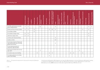
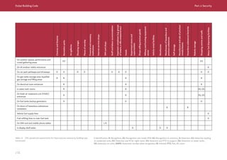
![Dubai Building Code Part B: Architecture
B 82
In all occupancies expect residential, a maximum of 33% of the water closets in male
toilet facilities may be substituted for urinals.
For any occupancy or space not listed in Table B.18, the minimum number of sanitary
fixtures shall be determined in accordance with the IBC [Ref. B.41].
Each residential unit in a building shall be provided with the necessary sanitary
facilities such as bathrooms, toilets, sinks, kitchen sinks. At least one bathroom shall
be provided for every residential unit.
B.8.1.3.2 Mosques and prayer rooms
Sanitary services shall be provided according to the number of worshippers, in
accordance with Table B.19.
Use Water closets Washbasins Ablution
spaces
Male Female Male Female
Mosques,
prayer rooms
1 per 100 worshippers 1 per 100 worshippers 1 per 50
worshippers
Table B.19 Minimum number of sanitary fixtures for mosques and prayer rooms
B.8.1.3.3 Swimming pools
Sanitary services shall be provided in accordance with Table B.20, with the following
exception:
the number of showers in swimming pools intended for residents’ exclusive use in
residential buildings may be reduced by 50%, provided that there is at least one
shower for each gender.
Use Water closets Washbasins Shower and tap for
washing feet
Male Female Male Female Male Female
Swimming
pools
1 per 75
for the
first 1500
occupants
1 per 120
occupants
for the
remainder
exceeding
1,500
1 per 40
for the
first 1,600
occupants
1 per 60
occupants
for the
remainder
exceeding
1,600
1 per 200
occupants
1 per 150
occupants
1 per 10
occupants
1 per 10
occupants
Table B.20 Minimum number of sanitary fixtures for swimming pools](https://image.slidesharecdn.com/dubaibuildingcodeenglish2021editionak-231227052107-72adb61a/85/Dubai-Building-Code_English_2021-Edition_AK-pdf-102-320.jpg)
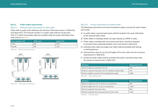
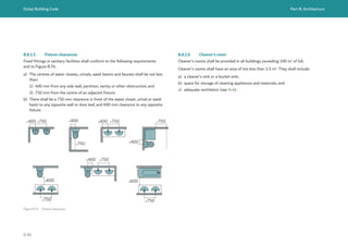
![Dubai Building Code Part B: Architecture
B 85
Occupancy Space type No. drinking fountains per
occupant load
Assembly Mosques and prayer rooms As required by IACAD
Restaurant, dining areas (where water is served
in restaurants, drinking fountains are not
required)
1 per 1,000
Ballrooms, exhibition hall, multipurpose
assembly halls, production studios, art gallery,
museums
1 per 500
Fixed seating spaces (cinemas, theatres and
similar)
Conference room, meeting rooms, library –
reading areas
1 per 500
Amusement spaces, gaming 1 per 1,000
Swimming pools 1 per 1,000
Business Offices 1 per 100
Retail, mall Shops and malls 1 per 1,000
Industrial and storage Factories, warehouse 1 per 500
Educational Schools 1 per 100 students
Kindergartens 1 per 100 students
Nurseries 1 per 100 children
Residential Labour accommodation 1 per 100
Student accommodation 1 per 100
B.8.2 Facilities for building occupants
B.8.2.1 Drinking fountains
Drinking fountains shall be provided as shown in Table B.24. They shall not be
installed in public restrooms. They shall be placed in safe and clean areas where they
will not obstruct building circulation.
Table B.24 Drinking fountain requirements
B.8.2.2 Feeding rooms (lactation rooms)
Feeding rooms shall be provided in all malls and amusement parks exceeding
1,000 m2
of GA and/or designed for more than 250 occupants.
At least one feeding room shall be provided within 300 m of any part of the building.
It is recommended that one feeding room is provided for each block of public toilets.
Dual feeding rooms may be provided to account for up to 50% of the total number
of feeding rooms required in the building.
A feeding room shall meet the following requirements.
a) Feeding rooms shall be designed to have sufficient space to facilitate ease
of movement with a pram and a child in the arms.
b) Feeding rooms shall be accessible.
c) Feeding rooms shall have an area of not less than 4.5 m2
and a dimension
on both sides of not less than 2.1 m.
An example of an individual feeding room is given in Figure B.77 and a dual feeding
room in Figure B.78.
B.8.2.3 First aid facilities
Public and business buildings shall be provided with first aid storage cupboards and
first aid rooms in accordance with Dubai Municipality Health and Safety guidelines
for first aid requirements [Ref. B.42].](https://image.slidesharecdn.com/dubaibuildingcodeenglish2021editionak-231227052107-72adb61a/85/Dubai-Building-Code_English_2021-Edition_AK-pdf-105-320.jpg)
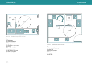
![Dubai Building Code Part B: Architecture
B 87
B.8.3 Building amenities
B.8.3.1 Gymnasiums, exercise rooms and fitness centres
When fitness facilities are provided in buildings, they shall meet the following
requirements.
a) Flooring and walls shall be acoustically insulated (see H.10.3.3), and if the
gymnasium space is located on the roof deck or above the apartments, their
floors and walls shall be treated with effective sound insulation materials.
Acoustic isolation from adjacent habitable spaces and occupiable spaces
shall be attained.
b) Exercise rooms which produce noises of vibrations (such as karate, weightlifting
gymnasiums and similar) should be situated at the lower building levels
or acoustically treated.
c) The number of changing rooms and lockers to be provided shall be determined
according to the expected number of users. At least one changing room/locker
shall be provided for both men and women.
B.8.3.2 Swimming pools
B.8.3.2.1 General requirements
Swimming pool designs shall conform to DM PH&SD guides [Ref. B.43 to Ref. B.45].
Swimming pools and decks shall be constructed of non-toxic, inert, impervious
and durable materials.
A swimming pool shall be configured to be safely patrolled, maintained and cleaned
and to provide good circulation of water.
Swimming pools shall be provided with lighting, both above and under the water
surface in order to provide an adequate illumination for the overall area of the pool.
The design of outdoor swimming pools located at roof, podium roofs and other
elevated locations shall provide privacy to adjacent buildings and shall be provided
with fall protection in accordance with B.4.2.5.2.
Sanitary facilities should be provided in accordance with B.8.1. A minimum of one
from each fixture type and one changing room shall be provided for each gender.
In accordance with Ch.3. of the UAE FLSC [Ref. B.1], two exits shall be provided
from exterior swimming pool decks, jogging tracks and landscaping areas when
the distance to a single exit exceeds 30 m.
B.8.3.2.2 Safety requirements
A suitable place for the lifeguard’s highchair, and notice boards with the guidelines
and policies for the swimmers to follow, shall be provided. A signboard showing water
depth shall be fitted at the pool’s edge. The signboard shall mark the location of
slope changes showing the maximum and minimum depth.
Provide sufficient number of life saving devices (rings, etc.) in the area. All details
shall be in accordance with swimming pools safety guidelines [Ref. B.43 to Ref. B.45].
The slope in the floor of the shallow area of the pool shall not exceed 10%.
The slip resistance of swimming pool floors shall conform to C.7.2.1.2.
Safety signage advising on the danger of diving into shallow areas and on the
prevention of drowning shall be provided as mandated by relevant Authority as
shown in Figure B.79.
Figure B.79 Safety sign (© International Code Council 2014. Figure based on diagram of the 2015 International
swimming pool and spa code. Washington, D.C.: International Code Council. Reproduced with permission. All
rights reserved. www.ICCSAFE.org)
WARNING
RESCUE:
NO DIVING! PREVENT
DROWNING
You can be
permanently injured.
Shallow water.
Watch children
at all time.](https://image.slidesharecdn.com/dubaibuildingcodeenglish2021editionak-231227052107-72adb61a/85/Dubai-Building-Code_English_2021-Edition_AK-pdf-107-320.jpg)
![Dubai Building Code Part B: Architecture
B 88
B.8.3.2.3 Swimming pool fences
Outdoor swimming pools shall be surrounded by a fence to protect against drowning.
The fence shall meet the following requirements:
a) The top of the fence shall be not less than 1,200 mm above FFL.
b) The vertical clearance between FFL and the bottom of the fence shall not
exceed 50 mm.
c) Openings in the fence shall not allow the passage of a 100 mm diameter sphere.
d) The fence enclosure shall be equipped with self-closing and self-latching gates.
e) Gates in fences shall be equipped with a locking device. Gates shall open away
from the pool.
The fence of a swimming pool shall be set back at least 1,200 mm from plot limits
and adjacent structures.
Swimming pool fences are not required in the following conditions.
1) A swimming pool fence is not required where the walls of adjacent structures
can perform as a fence or a protective barrier to the swimming pool. Doors with
direct access to the pool through the wall shall be equipped with an audio alarm
that provides an audio warning when the door is opened, or the door shall be
self-closing with self-latching devices.
2) A swimming pool that has a power safety cover conforming to ASTM F1346 is
not required to have a swimming pool fence.
3) Where the pool is adjacent to the edge of a natural body of water and public
access is not allowed along the shoreline, a barrier is not required between the
water body and the pool.
4) A swimming pool fence is not required where there are full-time lifeguards
patrolling the pool, together with pool supervision systems in accordance with
Public swimming pools safety guidelines [Ref. B.43].
Swimming pools designated for children shall be separated from swimming pools
designated for adults with protective barriers.
Pools and their surroundings shall be free of any dangerous obstacles.
Operable windows adjacent to the pool shall have a sill height of not less than
1,200 mm above the indoor FFL.](https://image.slidesharecdn.com/dubaibuildingcodeenglish2021editionak-231227052107-72adb61a/85/Dubai-Building-Code_English_2021-Edition_AK-pdf-108-320.jpg)
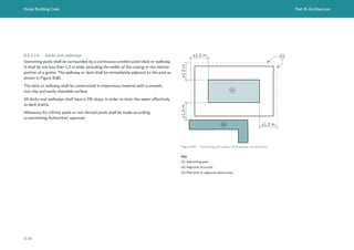
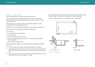
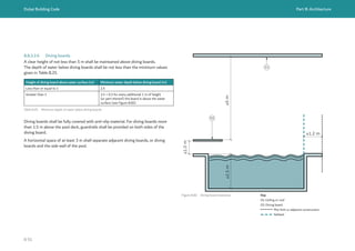
![Dubai Building Code Part B: Architecture
B 93
Prayer rooms should be positioned in proximity to toilet facilities in the building to
minimize travel distance between both facilities. If toilet facilities are not available
nearby, additional toilet facilities may be provided that shall meet the following
requirements.
a) Toilets shall not be set or located toward Qibla direction of the prayer rooms,
according to the Islamic doctrine. No single praying space shall face toilet
facilities.
b) The location and entrance of toilet facilities shall be separated from the prayer
room and ablution areas.
B.8.3.4 Open spaces
When open spaces are provided, landscape species shall be selected in accordance
with B.10.5.
Shading calculations and shading provisions in public areas conform to B.10.5.
B.8.4 Service facilities
Service rooms in the basements of buildings shall meet all of the requirements
in Table 1.9, Ch. 1 of UAE FLSC [Ref. B.1].
Table 1.9, Ch. 1 of UAE FLSC [Ref. B.1] does not permit RMU rooms in the
basements of buildings.
Transformer rooms, low voltage switchgear rooms, high voltage rooms and generator
rooms are preferred at ground level, but are permitted in basements by Dubai
Electricity and Water Authority (DEWA) and Dubai Civil Defence (DCD) provided
that the design conforms to G.7.6 and Table 1.9, Ch. 1 of the UAE FLSC [Ref. B.1].
Waste rooms are preferred at ground level, but are permitted in basements by DCD
provided that the design meets the following criteria.
a) The room is 1 h fire resistance rated, including a 1 h fire door and fire resistance
rated opening protectives.
b) The room is no more than one level below ground level.
c) The room is provided with a dedicated mechanical ventilation system direct
to outside to achieve 10 air changes/h, in accordance with Section 2.17, Ch. 10
of UAE FLSC [Ref. B.1].](https://image.slidesharecdn.com/dubaibuildingcodeenglish2021editionak-231227052107-72adb61a/85/Dubai-Building-Code_English_2021-Edition_AK-pdf-113-320.jpg)
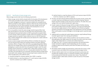
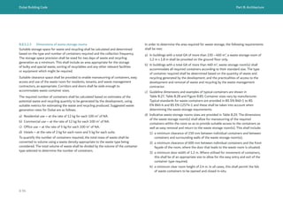
![Dubai Building Code Part B: Architecture
B 100
B.9 Architectural requirements for specific building types and spaces
B.9.1 General applicable requirements
This section details specific requirements for different building types.
These requirements shall be met in addition to all applicable requirements in the rest
of Part B.
The fire safety aspects of building design shall be in accordance with Ch. 1 to Ch.3
of UAE FLSC [Ref. B.1], based on occupancy classification, building height and/
or building depth, together with the occupancy-specific fire separation and egress
requirements given in Section 5, Ch. 3 of UAE FLSC [Ref. B.1].
Building design shall also follow applicable health and safety requirements
[Ref. B.42 to Ref. B.54].
B.9.2 Fire separating construction
Fire separating construction shall be provided in accordance with Table 1.9,
Ch. 1 of UAE FLSC [Ref. B.1].
B.9.3 Cinemas, theatres and auditoria
The architectural design of mezzanines, balconies, aisles and seating arrangements
in cinemas, theatres and auditoria shall conform to the minimum requirements given
in Section 5.1, Ch. 3 of UAE FLSC [Ref. B.1].
Where there is a well-defined main entrance or exit from cinemas, theatres and
auditoria, it shall be designed to accommodate two thirds of the total occupant load.
B.9.4 Mosques
B.9.4.1 General requirements
The following requirements and recommendations apply to the space planning
of mosques.
a) The size of mosques should be sufficient for the population density they serve,
taking into account the number of mosques within proximate locations, as well
as the other plots reserved for mosque construction in the future.
b) Future expansions of mosque facilities should be taken into account.
c) Professionals involved in the design and construction of mosques shall have
knowledge and experience of Islamic architecture.
d) The direction of prayer and flow of movement inside the mosque shall be taken
into account.
e) Vehicular and pedestrian movement inside the mosque plot shall segregated
to avoid interference with the movement of worshippers to and from the
mosque’s buildings and service blocks.](https://image.slidesharecdn.com/dubaibuildingcodeenglish2021editionak-231227052107-72adb61a/85/Dubai-Building-Code_English_2021-Edition_AK-pdf-120-320.jpg)
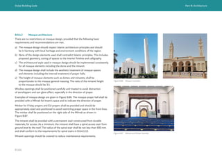
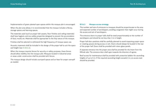
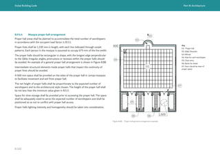
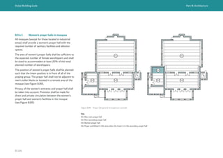
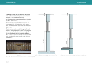
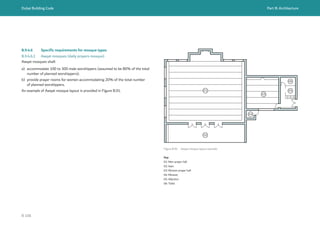
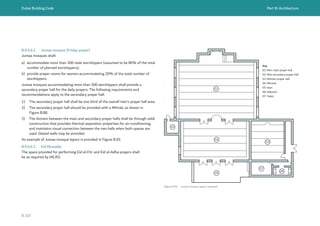
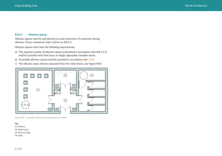
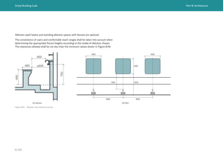
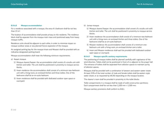
![Dubai Building Code Part B: Architecture
B 111
B.9.5 Restaurants and food facilities
B.9.5.1.1 General
The requirements in this subsection apply to the following spaces:
a) restaurants;
b) food services and beverage sales outlets such as:
1) coffee shops;
2) juice serving outlets;
3) grocery shops;
4) farm and fruit slate outlets;
5) sweet refreshment;
6) flour mills;
7) roasters;
8) frozen and chilled cold stores for food facilities storage;
9) bakeries and pastries;
10) retail supermarkets; and
11) sea food sales outlets.
Spaces shall be equipped with the necessary sanitary, health and safety facilities and
minimum kitchen areas in accordance with health and safety requirements issued
by DM, General Conditions for Licensing of Food Establishments [Ref. B.55].
B.9.5.1.2 Food preparation
Food preparation areas shall be designed based on the food and beverage items
to be offered and the flow of food between the preparation area and the diner.
The design process in PD ISO/TS 22002-2 shall be followed to control the
operational conditions within a food establishment and to promote environmental
conditions that are favourable for the production of safe food.
Operator brand standards (e.g. hotels, schools) shall be followed where applicable.
Food preparation areas in healthcare facilities shall conform to the DHA regulations
and guidelines [Ref. B.3 to Ref. B.18].
The intersection between the walls, the floors and the ceiling shall be sealed and
rounded to facilitate the cleaning process.
B.9.5.1.3 Kitchen requirements
The floors, walls and ceilings of kitchens shall be made of a smooth material that is
non-absorbent, non-combustible, non-toxic, crack-free and easily cleaned.
Floors shall be hard-surfaced, non-absorbent and drained. They shall be constructed
with waterproof, non-absorbent washable materials without fissures or crevices.
Wall finishes shall be smooth, waterproof, resistant to fracture, light-coloured and
readily cleanable.
Working surfaces for preparation of food shall be manufactured from stainless steel
or other approved impervious material to facilitate cleaning and maintenance of
hygienic conditions.
Gas supplies shall be in accordance with Ch. 11 of UAE FLSC [Ref. B.1].
Kitchen hoods and associated kitchen extract ductwork shall be provided to all areas
involving cooking activities, i.e. stoves, gas rings, tandoors, etc.](https://image.slidesharecdn.com/dubaibuildingcodeenglish2021editionak-231227052107-72adb61a/85/Dubai-Building-Code_English_2021-Edition_AK-pdf-131-320.jpg)
![Dubai Building Code Part B: Architecture
B 112
Kitchen hoods and associated kitchen extract duct work shall be designed and
installed in accordance with H.4.12.15 and UAE FLSC [Ref. B.1].
Chimneys installed in bakeries, restaurants and roasteries shall be located on the rear
side of the plot, or inside shafts and ducts.
The position, height and ventilation of chimneys shall be determined in accordance
with H.4.12.18.
Cold stores and freezers doors shall be openable from both sides. Safety releases
shall be provided on the insides of doors to avoid risk of accidental entrapment.
B.9.6 Educational facilities
B.9.6.1 General requirements
The requirements in this subsection apply to all educational facilities.
Educational facilities shall be located in designated plots in accordance with the
affection plan, land use classification and DCRs. Building heights and number of
floors allowed shall conform to planning regulations.
Educational buildings shall be designed in accordance with the DM PH&SD guides
[Ref. B.49, Ref. B.50].
Educational facilities shall meet the following requirements.
a) Daylighting provisions and acoustical treatment shall be prioritized for classrooms
and teaching spaces.
b) Educational facilities shall be equipped with a health clinic conforming to DHA
school clinic regulations [Ref. B.9].
c) Facilities shall include rooms for management staff, teachers, administrators and
supervisors, and waiting areas for parents. The areas of these rooms shall be
suitable for the number of staff in the facility.
d) The number of students permitted in each classroom shall be determined in
accordance with DM planning guidelines for public amenities [Ref. B.56] and the
Ministry of Education requirements.
e) Segregation of vehicular and pedestrian movement shall be provided inside the
facility to avoid intersection with movement of students to and from the facility’s
buildings. Bus pick-up and drop-off areas shall be located in a safe area, away
from vehicular traffic, for student circulation.
f) Separate parking areas should be provided for school buses and cars
g) Sanitary requirements for students shall be based on the fixture dimensions
defined in C.8.3.4.4 and the reach ranges defined in C.5.7.3.
B.9.6.2 Schools
Natural and artificial lighting shall be configured to avoid glare on vertical writing
surfaces and on students’ desks. For window orientation, it is preferable that window
openings face the left side of classrooms.
The school shall have a library, with adequate area to accommodate the number
of students in the school.
The school shall include sports courts according to the requirements applied
by the Ministry of Education.
The school shall have at least one canteen or dining hall. The canteen shall
be of an adequate size to serve the students.
The school shall have adequate number of laboratories, computer rooms,
and activities hall (multipurpose hall or auditorium).
School shall have allocated area for playing fields and open spaces. These areas
should not be less than 200% of the area allocated to classrooms, with 30% of these
spaces shaded. A mast for the flag should be provided.
First grade student classrooms shall be located on the ground floor.](https://image.slidesharecdn.com/dubaibuildingcodeenglish2021editionak-231227052107-72adb61a/85/Dubai-Building-Code_English_2021-Edition_AK-pdf-132-320.jpg)
![Dubai Building Code Part B: Architecture
B 113
Laboratory facilities shall be distanced from classroom areas.
Laboratories shall be provided with sufficient means of exhaust systems when the
facility is planned to be used for conducting chemical experiments.
Stairways for regular use by school students shall conform to B.6.4.1.6.
Minimum fire separation and egress requirements for schools are provided in Section
5.3.2, Ch. 3 of UAE FLSC [Ref. B.1].
B.9.6.3 Kindergartens
Kindergartens shall have playgrounds and open space of an area not less than 200%
of the area allocated to classrooms. At least 30% of this area shall be shaded. Part of
this area shall be planted and part of it shall be provided with sand/playground areas.
Play equipment and recreational facilities shall be provided for children.
Kindergartens shall have at least one canteen and a multipurpose hall. The canteen
shall be of an adequate size to serve the students and shall conform to health and
safety requirements [Ref. B.50, Ref. B.55].
Kindergarten classrooms shall be provided at ground level only.
Minimum fire separation and egress requirements for kindergartens are provided
in Section 5.3.1, Ch. 3 of UAE FLSC [Ref. B.1].
B.9.6.4 Nurseries
The clear distance between beds in the nursery rooms shall be not less than
1,000 mm.
Nurseries shall be provided with a large shaded and planted playground including
a sand pit, covering an area that is suitable in proportion to the number of children
enrolled, with a minimum area of 0.6 m2
per child
Nurseries shall be located at the ground level only.
Minimum fire separation and egress requirements for nurseries are provided
in Section 5.3.1, Ch. 3 of UAE FLSC [Ref. B.1].
B.9.7 Residential buildings
B.9.7.1 Apartment buildings
Apartment buildings shall be located in designated plots in accordance with the
affection plan, land use classification and DCRs.
Minimum fire separation and egress requirements for apartment buildings are
provided in Section 5.5.1, Ch. 3 of UAE FLSC [Ref. B.1].
All dwelling units in apartments shall be separated by 1 h fire resisting construction
as required by Table 1.9, Ch. 1 of UAE FLSC [Ref. B.1].
B.9.7.2 Labour accommodation
B.9.7.2.1 General building requirements
Labour accommodation shall be located in designated plots in accordance with the
affection plan, land use classification and DCRs.
Labour accommodation shall be constructed from permanent use, durable and
sustainable materials. Temporary installations shall not be used.
The accommodation buildings shall be separated from kitchens, workshops and
stores in accordance with UAE FLSC [Ref. B.1].
Prayer rooms shall be provided in accordance with B.8.3.3. Prayer rooms shall be
accessible to all occupants, with proximity to other communal amenities.
All residential rooms, kitchens, dining rooms and halls shall be provided with
ventilation and air conditioning according to H.4.
Minimum fire separation and egress requirements for labour accommodation are
provided in Section 5.5.3, Ch. 3 of UAE FLSC [Ref. B.1].](https://image.slidesharecdn.com/dubaibuildingcodeenglish2021editionak-231227052107-72adb61a/85/Dubai-Building-Code_English_2021-Edition_AK-pdf-133-320.jpg)
![Dubai Building Code Part B: Architecture
B 114
B.9.7.2.2 Labour accommodation rooms
The number of workers in each room shall not exceed 8 workers.
A supervisor’s room shall be provided for every 40 labourers. The room shall include
separate sanitary facilities for the supervisor.
Doors to rooms shall not open directly into the road or sikka. The building’s main
entrance shall be accessible within plot limits.
If double-deck bunks are used, the clear distance between the lower and upper bunk
shall be not less than 0.9 m. Triple-deck bunks shall not be used.
Toilets and bathroom blocks shall be provided with all necessary fixtures. Water tanks
shall be covered with sun protection to provide room temperature water in summer.
All sleeping units in labour accommodation shall be separated by 1 h fire resisting
construction as required by Table 1.9, Ch. 1 of UAE FLSC [Ref. B.1].
B.9.7.2.3 Labour accommodation amenities
Labour accommodation amenities shall meet the following requirements.
a) Multipurpose halls (dining and TV) shall have areas proportionate to the number
of workers, accommodating at least 30% of building occupants at a single time.
These halls shall be provided with furniture and equipment for its intended
purpose, as follows.
1) An adequately sized kitchen shall be provided for food preparation with a total
area not less than one third of the dining hall area. Kitchens shall be located
such that they are accessible to all users on the ground floor of the building.
2) The dining halls shall be located on the ground floor and connect directly to
the kitchen. The design and furnishings of the kitchen shall meet the general
criteria for licensing food facilities [Ref. B.55].
b) Indoor recreational facilities shall occupy not less than 25% of the total net area.
c) Space provisions for each of these amenities shall conform to B.5.1.
d) The travel distance between water fountains shall be not more than 30 m.
e) A first aid room with an area of not less than 10 m2
shall be provided at the rate
of one per thousand workers and at a minimum of one per labour accommodation
building. The room shall conform to the DM PH&SD guidelines for first aid
[Ref. B.42].
f) A room for workers’ equipment shall be provided at the rate of 0.1 m2
per worker
and an area of not less than 10 m2
.
g) A laundry tray or tub for every 30 persons shall be provided, along with places
for drying laundry.
B.9.7.3 Staff accommodation
Staff accommodation shall be located in designated plots in accordance with the
affection plan, land use classification and DCRs.
Staff accommodation shall be of permanent construction. Temporary structures shall
not be used.
Each floor for staff accommodation shall be provided with communal kitchen, dining
area, and lounge. The dining and lounge area shall be able to accommodate one third
of the floor occupants at a single time. At least one kitchen and one lounge shall be
provided for every 400 m2
of NA. The kitchen area shall be not less than 25 m2
.
Rooms shall be limited to single or double occupancy. Each room shall have an
attached toilet.
Rooms sizes for staff accommodation shall conform to Table B.31.
Room type Minimum area (m2
) Minimum dimensions (m)
Single occupancy – inclusive of en-suite toilet 13 2.7
Double occupancy – inclusive of en-suite toilet 20 2.7
Table B.31 Rooms sizes for staff accommodation](https://image.slidesharecdn.com/dubaibuildingcodeenglish2021editionak-231227052107-72adb61a/85/Dubai-Building-Code_English_2021-Edition_AK-pdf-134-320.jpg)
![Dubai Building Code Part B: Architecture
B 115
Minimum fire separation and egress requirements for staff accommodation are
provided in Section 5.5.2, Ch. 3 of UAE FLSC [Ref. B.1].
All sleeping units in staff accommodation shall be separated by 1 h fire resisting
construction as required by Table 1.9, Ch. 1 of UAE FLSC [Ref. B.1].
B.9.7.4 Student accommodation
Student accommodation shall be located in designated plots in accordance with
the affection plan, land use classification and DCR.
Rooms sizes for student accommodation shall conform to Table B.32.
The sanitary fixtures numbers specified in Table B.18 shall be provided as a minimum.
Rooms may be provided with separate attached toilets.
Space planning of student accommodation shall take into account safety and security.
Privacy of accommodation shall be provided. Male and female residences shall
be segregated.
Room type Minimum area (m2
) Minimum dimensions – length
and width of a room (m)
Single occupancy – exclusive of
toilet area
7 2.4
Shared occupancy – exclusive of
toilet area
5 for each student 2.4
Table B.32 Rooms sizes for student accommodation
B.9.8 Industrial and warehouse facilities
Industrial/factory/workshop and warehouse/storage buildings shall be located
in a designated industrial plot in accordance with the affection plan, land use
classification and DCRs.
Setbacks for industrial and warehouse plots shall conform to affection plans
and DCRs.
Office space within industrial and warehouse buildings shall be provided according
to planning Authority’s allowance and shall be limited to a maximum of 20% of the
total GA.
When the operation of the building expects a large quantity of heavy vehicle access
of more than one trip per 100 m3
of GA at peak hour [Ref. B.40], segregated access
points should be provided for light vehicles and heavy vehicles or trucks.
No doors shall open directly into roadway side, except for emergency exit doors,
which shall be set at a minimum of 2 m from the roadway edge. A landing shall
be provided on the exterior side of the exit door at the same height as the door
in accordance with Table 3.1, Ch. 3 of UAE FLSC [Ref. B.1].
Vehicular entrances shall lead to loading/unloading areas.
Loading and unloading areas may be open to sky or covered. The manoeuvring area
in the loading and unloading areas shall conform to B.7.3 or be based on specialist
traffic and manoeuvring analysis.
The net internal height of any factory/workshop or warehouse/storage shall
be sufficient to support the processes occurring within.
Adequate space shall be provided for staff dining rooms, pantries and changing
facilities, accommodating at least 25% of staff at the same time.](https://image.slidesharecdn.com/dubaibuildingcodeenglish2021editionak-231227052107-72adb61a/85/Dubai-Building-Code_English_2021-Edition_AK-pdf-135-320.jpg)
![Dubai Building Code Part B: Architecture
B 116
Kitchen facilities shall be separated from factory/workshop or warehouse/storage as
mandated by UAE FLSC [Ref. B.1].
Minimum fire separation and egress requirements for warehouse/storage buildings
are provided in Section 5.14, Ch. 3 of UAE FLSC [Ref. B.1].
Minimum fire separation and egress requirements for industrial/factory/workshop
buildings are provided in Section 5.15, Ch. 3 of UAE FLSC [Ref. B.1].
Multitenant warehouses shall be separated by 1 h fire resisting construction as
required by Table 1.9, Ch. 1 of UAE FLSC [Ref. B.1].](https://image.slidesharecdn.com/dubaibuildingcodeenglish2021editionak-231227052107-72adb61a/85/Dubai-Building-Code_English_2021-Edition_AK-pdf-136-320.jpg)
![Dubai Building Code Part B: Architecture
B 117
B.9.9 Motor fuel dispensing facilities
Motor fuel dispensing facilities shall be located in a
designated plot in accordance with the affection plan,
land use classification and DCRs.
Motor fuel dispensing facilities shall conform to all
applicable requirements of Section 3, Ch. 13 of UAE
FLSC [Ref. B.1] and of the operator. All health and
safety and security design requirements shall be
fulfilled to ensure safety of users, workers and the
facility itself.
Vehicle entrances and exits shall meet requirements for
turning radius and dimensions as shown in Figure B.95.
Figure B.95 Access to fuel facility
03
02
04
01
04
≥20.0 m
01
≥25.0 m
R
≥
1
0
.
0
m
R≥10.0 m
R≥10.0
m
R≥10.0
m
6.0 m
6.0 m
45.0°
6.0 m
45.0°
45.0°
6.0 m
≥15.0 m
45.0°
Key
01: Road
02: Gas station with fuel pump islands
obliquely angled (mainly for one-way traffic)
03: Access to corner gas station](https://image.slidesharecdn.com/dubaibuildingcodeenglish2021editionak-231227052107-72adb61a/85/Dubai-Building-Code_English_2021-Edition_AK-pdf-137-320.jpg)
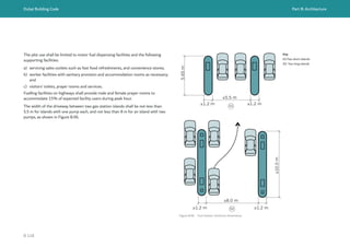
![Dubai Building Code Part B: Architecture
B 119
B.9.10 Healthcare facilities
Healthcare buildings shall be located in a designated plot in accordance with the
affection plan, land use classification and DCRs.
Healthcare buildings, including but not limited to hospitals, outpatients’ facilities,
surgical centres, pharmacies and similar facilities, shall be designed according to DHA
regulations and guidelines [Ref. B.3 to Ref. B.18] in addition to laws set out by the
ministry of health and the DCD in UAE FLSC [Ref. B.1].
Design of healthcare facilities for Dubai Healthcare City Authority shall also follow
the FGI guidelines [Ref. B.56].
The following requirements shall be met in the design of healthcare facilities.
a) The healthcare facility shall be designed ensuring independent access, amenities
and building service systems. The same requirements apply to facilities located
within mixed-use buildings and malls.
b) Prayer rooms shall be provided in healthcare facilities in accordance with B.8.3.3.
c) Privacy of treatment facilities and segregation of men and women shall be
provided.
B.9.11 Hotel establishments
Hotels establishments should adhere to the classification criteria set by the
Department of Tourism and Commerce Marketing (DTCM) according to the level
of classification pursued [Ref. B.19 to Ref. B.36].
Minimum room areas and space provisions shall conform to DTCM requirements
[Ref. B.19 to Ref. B.36].
Minimum fire separation and egress requirements for hotel accommodation
are provided in Section 5.9, Ch. 3 of UAE FLSC [Ref. B.1].
Hotel suites and standard rooms shall be separated by 1 h fire resisting construction
as required by Table 1.9, Ch. 1 of UAE FLSC [Ref. B.1].
Hotel apartments shall be separated by 1 h fire resisting construction as required
by Table 1.9, Ch. 1 of UAE FLSC [Ref. B.1].
B.9.12 Utility buildings
The design of utility buildings, such as substations, waste water treatment plant
and district cooling buildings, shall conform to the minimum requirements
of Ch. 14 of UAE FLSC [Ref. B.1].
Table 14.1, 5 (viii), Ch. 14 of UAE FLSC [Ref. B.1] is amended by DCD to align with
DEWA requirements for access around equipment. Batteries, relay and control panels
and other equipment in the substation shall be arranged such that a minimum
of 1,000 mm exit access width is available between such arrangements or between
equipment and wall.
Detailed requirements for substations are given in G.7.](https://image.slidesharecdn.com/dubaibuildingcodeenglish2021editionak-231227052107-72adb61a/85/Dubai-Building-Code_English_2021-Edition_AK-pdf-139-320.jpg)
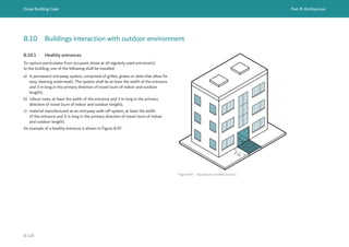
![Dubai Building Code Part B: Architecture
B 121
B.10.2 Screening of building equipment
All outdoor mechanical equipment, including antennas, rooftop equipment and refuse
storage areas, should be concealed from public view by solid walls, screens, fences,
parapet walls, enclosing structures or landscape.
B.10.3 Building fences and boundary walls
Building fences and boundary walls shall be provided according to each building
or occupancy operational needs and as specified in affection plan or DCR.
When fences are provided, the fence height shall be limited to a maximum of 3 m,
except for utility service buildings. Utility service building fences shall be provided
according to the utility operational requirements.
B.10.4 Smoking areas
Smoking is strictly prohibited in all public areas in accordance with Local Order
No 11 – 2003 [Ref. B.57].
Places where smoking is allowed shall be determined in accordance with the
conditions listed in the Manual of regulating smoking in public places issued by the
Authority [Ref. B.58]. This manual defines the public places where smoking is strictly
prohibited and places where smoking is allowed under specific conditions.
Designated smoking areas shall be at least 7.5 m away (see Figure B.98) from
the entrances of the building, doors and operable windows and outdoor air intakes
of ventilation systems.
An annual permit is issued from the competent department of the Authority
for all places where smoking is allowed, upon submission of all required documents
and drawings mentioned in the guideline.
Figure B.98 Illustration of acceptable location of designated smoking area
≥7.5m](https://image.slidesharecdn.com/dubaibuildingcodeenglish2021editionak-231227052107-72adb61a/85/Dubai-Building-Code_English_2021-Edition_AK-pdf-141-320.jpg)
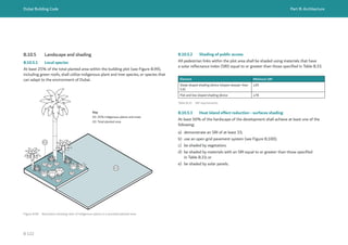
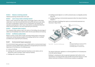
![Dubai Building Code Part B: Architecture
B 125
B.11 Wayfinding in buildings
B.11.1 General
When there is a well-designed wayfinding system, people are able to understand
their environment. This provides users with a sense of control and reduces anxiety,
fear and stress.
From the user perspective, the wayfinding process involves four stages as given
in Table B.34.
Stage of process Description of stage
Orientation The attempt to determine one’s own location in a physical space in
relation to the chosen destination.
Route decision The selection of a course of direction to the destination.
Route monitoring Checking to make sure that the selected route is heading towards to
the destination.
Destination recognition When the destination is recognized.
Table B.34 Wayfinding process
B.11.2 General requirements
The following requirements and recommendations apply to wayfinding elements,
including visual, acoustic and tactile references.
a) People shall be able to identify their location in a building without walking more
than 70 m in open spaces and 30 m inside buildings.
b) All business and administration buildings shall display the name of the building
in the façade and shall provide a directory adjacent to the entrance which lists
all facilities or services contained in the building. This building directory may
be digital/dynamic or static.
c) Orientation signs to the exit, toilet and select destination or amenities shall
be present at corridor intersections and at every 30 m.
d) Fire exit access and fire exits shall be identified by exit signs as mandated
by Ch. 5 of UAE FLSC [Ref. B.1].
e) Visual clutter caused by inappropriately designed or located signage and other
elements in the environment shall be avoided.
f) The environment’s identity shall be clearly and consistently communicated
through the design of graphic elements to increase the users’ recognition during
navigation.
g) Signage should be positioned at key decision-making points on the path of travel.
It should be positioned over the path of travel at a height of not less than 2,100
mm, measured from FFL to the bottom of the sign, and high above head level
in high pedestrian traffic areas. Signage should be positioned to avoid shaded
areas and glare.
h) Information on signs should be kept to a minimum, without duplication.
Complex information should be broken down, beginning with general
information and moving towards more specific information.
i) Standardized nomenclature should be adopted to organize information
in similar environments.
j) Signage should be provided with both English and Arabic text. Arabic,
being the primary language texts, shall be aligned to the right.](https://image.slidesharecdn.com/dubaibuildingcodeenglish2021editionak-231227052107-72adb61a/85/Dubai-Building-Code_English_2021-Edition_AK-pdf-145-320.jpg)
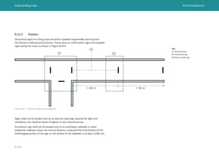
![Dubai Building Code Part B: Architecture
B 127
Table B.35 Sign types
Wayfinding process Sign type Use of the sign
Orientation Information Indicates specific locations
within an environment, helping
in understanding.
Route decision and monitoring Directional Guides users through
the environment to their
destination.
Recognition Identity Displays necessary information
for users to identify a place.
Advice Advisory and regulatory Draws attention to objects,
situations or behaviours that
might affect the wellbeing
and convenience of users or
activities in the environment.
B.11.4 Signage types
B.11.4.1 Types
Fire exit access and fire exits shall be identified by exit signs as mandated by Ch. 5 of
UAE FLSC [Ref. B.1].
Wayfinding signage is classified according to wayfinding processes as shown in
Table B.35.
Figure B.103 Example of a good arrow design
B.11.4.2 Information signs
Information displaying the nearest exit, nearest toilets and the distance to them shall
be displayed at adequate intervals in buildings, but not more than 30 m apart.
All maps presented in open spaces shall be designed with the North in the upper part
and displaying a North symbol.
Maps and directories shall be mounted in entrances to help building occupants to
navigate.
Maps should be easy to understand, without too much information. They shall use
contracted colours and symbols to aid understanding.
A graphic device such as a red star or red target symbol shall be used to indicate the
user’s positioning on the map.
B.11.4.3 Directional signs
Directional signs shall be used to give information to the users about how to reach
their destination.
Arrows shall be designed with the shaft longer than the header stem. The thickness
shall be the same in all arrow lines. Header lines shall have an angle of 45°
(see Figure B.103). Arrow alignment, typology and hierarchy are shown in Table B.36.
Examples of directional signs are given in Figure B.104.](https://image.slidesharecdn.com/dubaibuildingcodeenglish2021editionak-231227052107-72adb61a/85/Dubai-Building-Code_English_2021-Edition_AK-pdf-147-320.jpg)
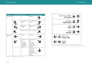
![Dubai Building Code Part B: Architecture
B 129
B.11.4.4 Identity signs
Identity signs are intended to identify a destination. They shall meet the following
requirements.
a) All fenced open spaces, such as parks, golf courses and hotels, shall display their
name at the entrance door.
b) All building façades shall display the name of the building as well as the Makani
number.
c) All doorframes shall present information on the service(s) available in the space.
Raised standardized pictograms and text with contrasted colour shall be used
to identify the different services. Signage shall be mounted at a height between
1,200 mm and 1,600 mm on the left of the door.
B.11.4.5 Advisory signs
Advisory signs shall be mounted to indicate safety procedures such as fire escape
routes, no smoking areas and other regulatory information.
Advisory signs such as evacuation plans, required by Ch. 5 of UAE FLSC [Ref. B.1]
shall be provided.
Advisory signs shall also be placed at rest areas, elevators, access points, etc., to
inform users about giving priority or give way to others (such as the elderly, people
with prams, pregnant women and persons with disabilities).
B.11.4.6 Digital screens
Screens should be matte, with a wide angle of vision and providing a good contrast. In
all instances, screens shall fulfil the following criteria.
a) Whenever installed in walls, screens should be visible at a height between 1,600
mm and 2,000 mm without interfering with the accessible route and with a slight
inclination (15°to 30°).
b) Digital screens should be visible from a distance of not less than 1,000 mm.
c) An interaction space as noted in Part C shall be provided in front of the screen.](https://image.slidesharecdn.com/dubaibuildingcodeenglish2021editionak-231227052107-72adb61a/85/Dubai-Building-Code_English_2021-Edition_AK-pdf-149-320.jpg)
![Dubai Building Code Part C: Accessibility
C 8
C.4.1 General
This Part specifies requirements for building elements, assemblies and components
that make up a building. The requirements relate to building use and circulation, and
to some elements of the exterior building environment, such as the accessibility of
public spaces.
This Part is applicable to common parts of multi-occupancy residential buildings and
accessible residential units within. It is not applicable to individual dwellings, villas or
townhouses. Requirements for individual dwellings are specified in Part K.
Stated dimensions are primarily based on adults, with additional specifications given
to suit children and people of varying heights. Where a facility is intended to serve
children, dimensions and other provisions can be adjusted to make them suitable for
children.
All areas of newly designed and newly constructed buildings and facilities shall
conform to these requirements.
Where a site, building, facility or space contains more than one use, each portion shall
conform to the applicable requirements for that application.
C.4.2 Accessible emergency provisions
People of determination shall be provided with an equal level of emergency
protection as others.
In addition to this Part, the provisions for emergency and alarm systems, refuge,
evacuation and egress shall be in accordance with UAE FLSC [Ref. C.1].
C.4.3 Gender equality
Where a building features segregated use by gender, the same level of accessibility
shall be provided for both genders.
C.4 Accessibility general requirements C.5 Accessible routes and circulation
C.5.1 General principles
Accessible routes shall be provided in accordance with the following requirements.
a) Site arrival points. A minimum of one accessible route shall be provided to each
building or facility’s accessible entrance from any of the following that serve it:
1) accessible parking spaces and accessible passenger loading zones
(see Figure C.1);
2) public streets and sidewalks; and
3) public transportation stops.
b) Within a site. A minimum of one accessible route shall connect accessible
buildings, accessible facilities, accessible elements and accessible spaces that are
on the same site.
c) Building entrances shall be provided in accordance with C.5.4.
d) Multi-storey buildings and facilities. A minimum of one accessible route shall
connect each story and mezzanine. Spaces exempted from the elevator provisions
in C.5.9.3 shall also be exempted from the provision of accessible routes and other
accessibility provisions.
e) Spaces and elements. A minimum of one accessible route shall connect the
accessible entrances of a building or facility with all accessible spaces and
elements within the building or facility.
f) Accessible routes shall be integrated with, or be located adjacent to, general
circulation routes available to building users.
g) Signage indicating accessible and general circulation routes shall be provided in
accordance with C.11.](https://image.slidesharecdn.com/dubaibuildingcodeenglish2021editionak-231227052107-72adb61a/85/Dubai-Building-Code_English_2021-Edition_AK-pdf-158-320.jpg)
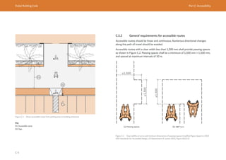
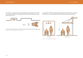
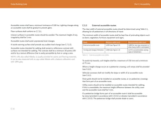
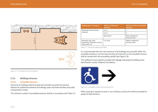
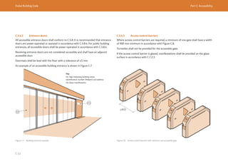
![Dubai Building Code Part C: Accessibility
C 14
C.5.5 Internal accessible routes
The clear width of internal accessible routes should be obtained from Table C.3,
allowing for all pedestrians in all directions of travel.
Route Minimum width (mm) Recommended width (mm)
Internal accessible route 1,000 (see Figure C.9) 1,200
Turning and change of direction 1,500 (see Figure C.2 and
Figure C.10)
1,575 to accommodate varying
types of wheelchairs
Table C.3 External accessible route widths
Access for wheelchair users shall be provided to all accessible rooms, spaces and
elements. Wheelchair users shall be able to pass other people and, where necessary,
turn through 180°. The minimum width of internal accessible routes shall be kept
free of protruding objects such as doors, vegetation, furniture, equipment and signs.
Corridors in buildings shall conform to Part B and Ch. 3 of UAE FLSC [Ref. C.1] in
addition to the accessible route minimum clear width requirements (see Figure C.10).
Figure C.9 Internal accessible route example
≥1,000
Ø1,500
≥1,000
Figure C.10 Accessible route clearances within corridors (© British Standards Institute. Figure extracted from
BS 8300. Permission to reproduce extracts from British Standards is granted by BSI Standards Limited (BSI).
No other use of this material is permitted).](https://image.slidesharecdn.com/dubaibuildingcodeenglish2021editionak-231227052107-72adb61a/85/Dubai-Building-Code_English_2021-Edition_AK-pdf-164-320.jpg)
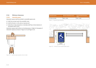
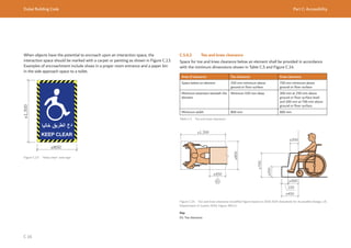
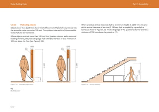
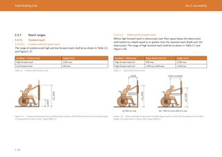
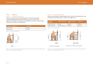
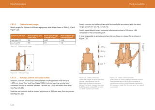
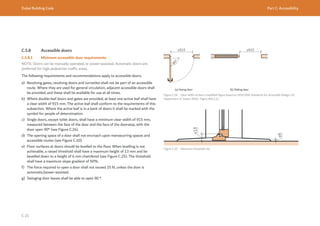
![Dubai Building Code Part C: Accessibility
C 22
C.5.8.2 Hardware requirements
C.5.8.2.1 Door opening hardware
Means of opening and closing (such as door handles, pull handles and push plates)
shall be placed at a height between 865 mm and 1,220 mm. They shall be easy to
grasp and use. Pressure mechanisms or levers shall be automatic, or easy to operate
with the elbow or a closed fist as shown in Figure C.26.
Door levers and handles shall be separated from the door by a minimum of 40 mm
(see Figure C.27 and Figure C.28).
To open sliding doors, a vertical fixed bar or pull handle shall be provided. The vertical
bar or pull handle shall be installed between 865 mm and 1,220 mm above the floor
(see Figure C.28).
Figure C.26 Lever mechanism operated by a closed fist
865-1,220
Figure C.27 Door lever
≥865
≤1,220
Figure C.28 Pull handle
Round knobs and thumb latches shall not be used because they require tight grasping
and finger control. Doors equipped with closers shall have a minimum closing time
of 5 s.
In high pedestrian traffic areas (such as washrooms), minimum 250 mm high kick
plates are recommended.
C.5.8.2.2 Vision panels
It is recommended that vision panels are provided for doors in entrance lobbies and
high traffic areas. Vision panels should be a minimum of 100 mm wide and should be
positioned vertically in the viewing range of wheelchair users (as described in C.7.1).
The provision of vision panels in fire doors shall conform to Ch. 1 and Ch. 3 of UAE
FLSC [Ref. C.1]. The guidance given in BS 8300 for door hardware, access control
systems and vision panels should be followed.](https://image.slidesharecdn.com/dubaibuildingcodeenglish2021editionak-231227052107-72adb61a/85/Dubai-Building-Code_English_2021-Edition_AK-pdf-172-320.jpg)
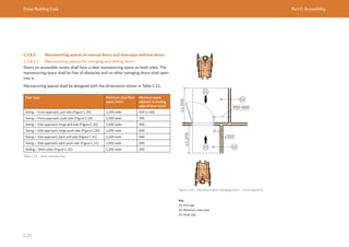
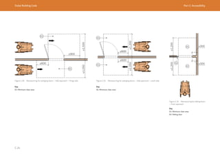
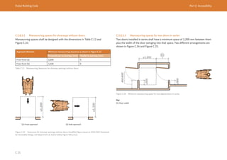
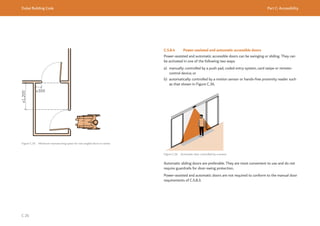
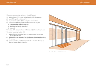
![Dubai Building Code Part C: Accessibility
C 28
C.5.9 Vertical circulation
C.5.9.1 Ramps
C.5.9.1.1 Accessible and pedestrian ramp requirements
The following requirements and recommendations apply to accessible and pedestrian
ramps.
a) Where ramps are used for means of egress, the width and number of ramps
required shall conform to with Section 3.7, Ch.3 of UAE FLSC [Ref. C.1].
b) Ramps shall be provided when a change in level has a gradient greater than 5%.
c) When ramps are provided, it is recommended that stepped access is also provided
for use by people with an ambulant disability.
d) The slope of a ramp shall meet the specifications given in Table C.13.
e) The maximum cross-slope gradient shall be 2%.
f) Ramp landings shall be provided if the ramp run exceeds 10 m (see C.5.9.1.3).
g) If a series of ramp runs rises more than 2.4 m, an alternative means of step-free
access, such as an enclosed elevator or a lift platform conforming to C.5.9.3,
should be provided.
Ramp rise Slope Length between landings
Recommended
(%)
Maximum
(%)
Recommended
(m)
Maximum
(m)
More than 1,000 mm 5 to 6 8.33 4 10
500 mm to 1,000 mm ≤7 8.33
Less than 500 mm ≤8 8.33
Table C.13 Ramp rises
C.5.9.1.2 Ramp runs
Ramp runs shall be designed in accordance with Figure C.38 and Figure C.39. The
following requirements and recommendations apply to ramp runs.
a) The usable clear width shall be a minimum of 1,000 mm when measured between
handrails.
b) The ramp level change should be indicated through a tactile warning surface or
change in the floor surface material with a difference of 30 points LRV.
c) Open ramps shall have outside edge protection as shown in Figure C.39.
d) Guardrails shall be provided in accordance with B.6.4.1.8.](https://image.slidesharecdn.com/dubaibuildingcodeenglish2021editionak-231227052107-72adb61a/85/Dubai-Building-Code_English_2021-Edition_AK-pdf-178-320.jpg)
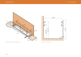
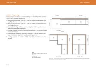
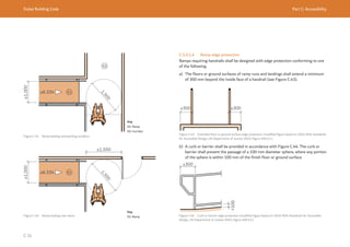
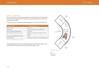
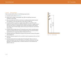
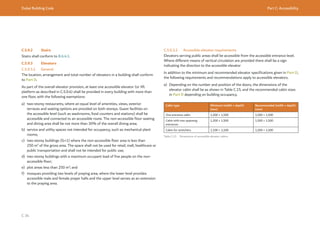
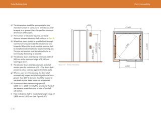
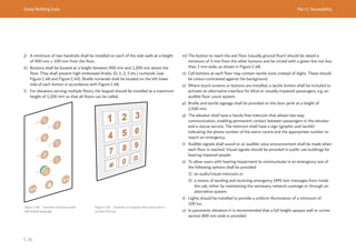
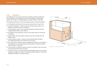
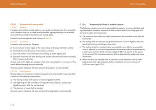
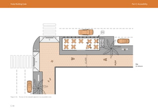
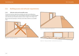
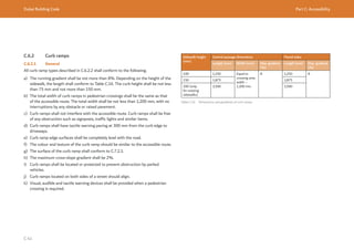
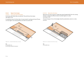
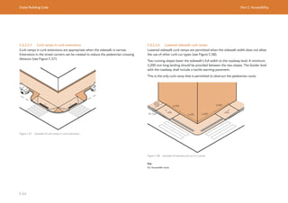
![Dubai Building Code Part C: Accessibility
C 44
C.6.3 Pickup and drop-off areas
Drop-off areas shall comply with Dubai Access Management manual requirements
[Ref. C.16] Chapter 7.2. Accessible drop-off areas shall include curb ramps
conforming to C.6.2.
Passenger drop-off and pickup areas shall provide a vehicular pull-up space in
accordance with [Ref. C.16].
C.6.4 Accessible parking
C.6.4.1 Accessible parking provision
Public or private parking areas associated with a public street, open space or building
shall have accessible parking spaces. These parking spaces shall be reserved for
holders of accessible parking stickers issued by any authorized jurisdiction.
The number of accessible parking spaces shall be obtained from Table C.17.
For hospitals and healthcare facilities, 10% of the overall parking capacity should be
accessible.
Accessible van parking should be provided at a rate of 10% of overall accessible
parking count. At least one accessible van parking space should be provided for each
building or facility.
Accessible parking spaces shall conform to the minimum dimensions in Table C.18.
Use of the building, establishment or area Minimum number of accessible spaces
All buildings except private housing 25 to 500 total parking
spaces
2% of the total, and a
minimum of one
More than 500 total
parking spaces
1% for additional
parking spaces over
500
Buildings with reserved seating space for
wheelchair users, such as cinemas and sport
facilities
One for every two reserved seating spaces for
wheelchair users
Buildings and open spaces without parking
facilities but with the following uses:
a) administration headquarters;
b) hospitals;
c) education buildings;
d) sport facilities;
e) beaches with accessible routes;
f) rehabilitation and day care centres; and
g) clinics.
Two bays in the public areas, as close as possible
to the building entrance (maximum 50 m)
Table C.17 Minimum number of accessible parking spaces
Parking type Parking space dimensions (m)
Car – angled and perpendicular 2.5 m × 5.5 m
Car – parallel – along the sidewalk 2.5 m × 6.0 m
Accessible van 3.35 m × 5.5 m
Table C.18 Parking dimensions](https://image.slidesharecdn.com/dubaibuildingcodeenglish2021editionak-231227052107-72adb61a/85/Dubai-Building-Code_English_2021-Edition_AK-pdf-194-320.jpg)
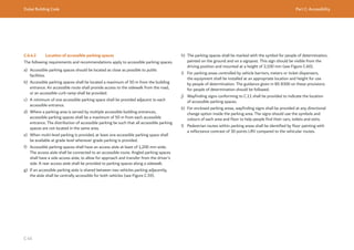
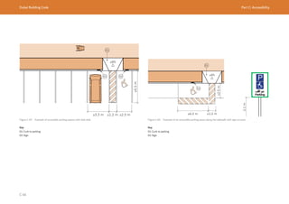
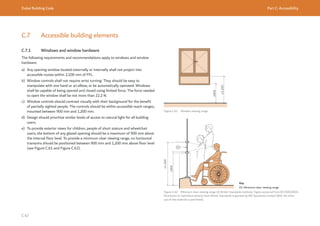
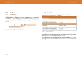
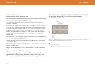
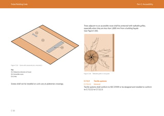
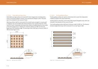
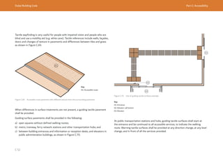
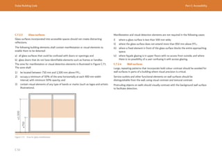
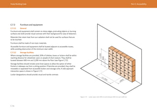
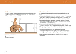
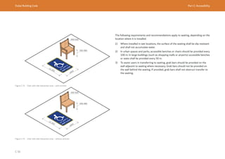
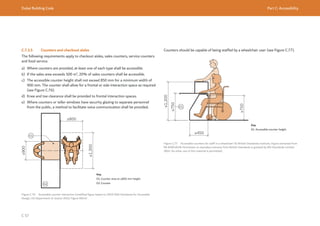
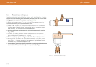
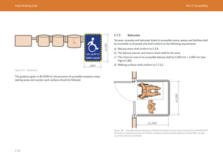
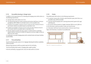
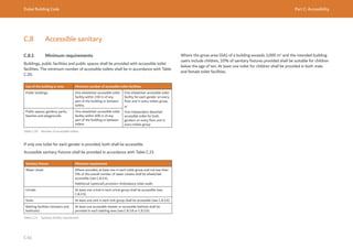
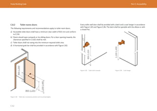
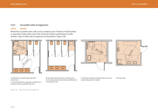
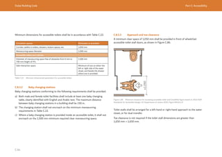
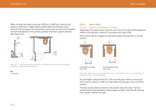
![Dubai Building Code Part C: Accessibility
C 66
C.8.3.4.2 Wheelchair accessible water closets
Wheelchair accessible water closets shall have a minimum clear interaction space
measuring 800 mm perpendicular from the water closet edge, and 1,300 mm
perpendicular from the rear wall [Figure C.89(a)].
Two side transfer water closets can also be used, provided an interaction space of
1,300 mm × 800 mm is provided on both sides of the water closet [Figure C.89(b)].
Figure C.89 Clearance for water closets
(a) Single side transfer (b) Double side transfer
≥1,300
≥800
≥1,300
≥800 ≥800
C.8.3.4.3 Grab bars for water closets
Grab bars shall conform to the general requirements of C.8.3.9.
For the provision of grab bars, either a single-sided transfer approach or a double-
sided transfer approach shall be used.
The following requirements and recommendations apply to single-sided transfer.
a) The minimum dimensions for toilets with single-sided transfer shall be in
accordance with Figure C.90.
b) Transfer horizontal grab bars shall be provided on both the back side of the water
closet and wall side, and shall:
1) have a support length of 750 mm to 900 mm; and
2) be mounted at a height of 700 mm to 850 mm.
c) The side wall grab bar shall have a maximum distance of 300 mm from the rear
wall and shall extend 300 mm minimum in front of the water closet
d) An additional foldable horizontal bar should be provided, mounted at 400 mm
to 450 mm from the water closet centre line, with a minimum length of 750 mm
to 900 mm, and mounted between 700 mm and 850 mm from floor level. When
a foldable horizontal bar is provided, the length of grab bar at the back of water
closet can be reduced to 600 mm.
e) A vertical bar on the side wall shall be provided with a support length of 600 mm
located at a minimum height of 800 mm from the floor as shown in Figure C.91.
The vertical grab bar shall be positioned at a maximum distance of 300 mm in
front of the toilet.
Ø
1
,
5
0
0
Ø
1
,
5
0
0
≥800
≥800
≥1,300
700-850
600
Figure C.90 Minimal dimensions for toilets with single-sided transfer](https://image.slidesharecdn.com/dubaibuildingcodeenglish2021editionak-231227052107-72adb61a/85/Dubai-Building-Code_English_2021-Edition_AK-pdf-216-320.jpg)
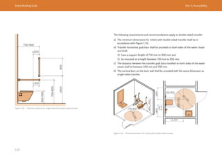
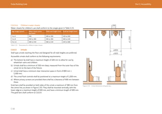
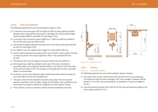
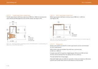
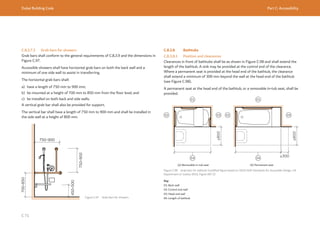
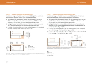
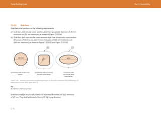
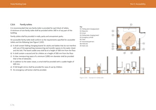
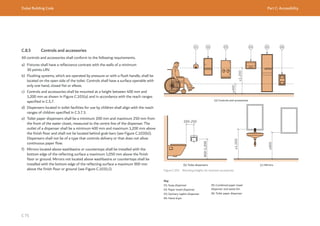
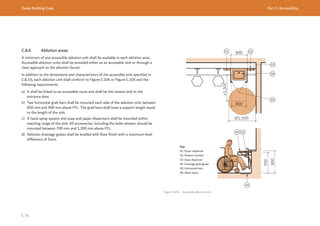
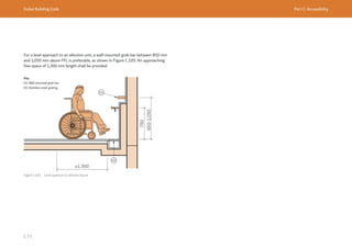
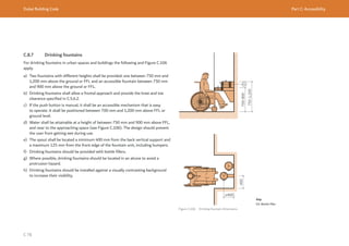
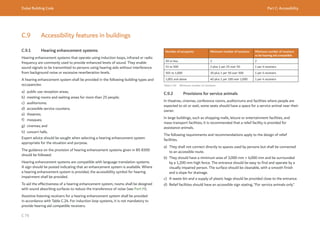
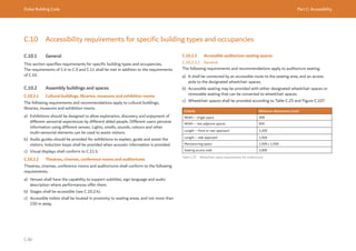
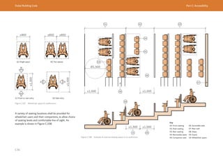
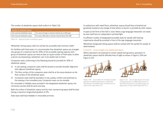
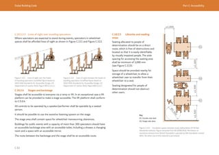
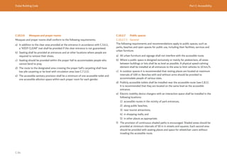
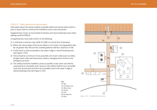
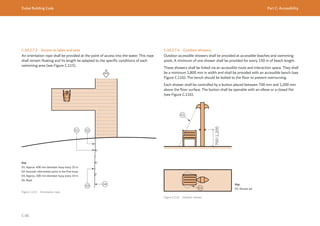
![Dubai Building Code Part C: Accessibility
C 87
C.10.2.7.5 Playgrounds
Playgrounds that offer a variety of play options (visual, auditory and tactile) are
preferred. To be accessible, a playground shall conform to the following requirements.
a) Each playground shall conform to the basic requirements for accessibility of fixed
accessible furniture (see C.7.3).
b) Playground surfaces shall consist of rubber or compacted sand.
c) The surfaces shall be smooth, firm and free of any sharp objects or projections, in
order to avoid injuries.
d) Playgrounds shall be designed to allow all children, regardless of their functional
limitations, and according to the age group for which the playgrounds are
intended, to enjoy and use a minimum of 50% of individual and group expected
activities.
e) All materials exposed to sun radiation shall not reach temperatures that can harm
the users.
f) Materials used to construct children's games (especially sliding ones) shall
not contain plastics or metals that produce electrostatic discharges that can
deprogram hearing aids. Any existing playground that produces this effect shall be
marked with a magnetic warning sign (see Figure C.117).
The provisions of the Americans with Disability Act (ADA) [Ref. C.2] should
be followed.
Figure C.117 Example of ISO and ANSI
magnetic warning signs
C.10.2.8 Swimming pools
C.10.2.8.1 General
For a public use swimming pool, an accessible deck shall be provided on at least two
sides of the pool. An accessible route shall link the pool with facilities and common
areas.
For a residential pool serving multiple units, the pool deck and amenities should
be accessible. Other private use swimming pool accessibility provisions should be
according to operation and users’ needs.
Public use swimming pools longer than 25 m, and other bathing pools, shall have a
minimum of one accessible means of entering the water.
Access to the water shall be by sloped entry or assisted elevation chair if the pool
length exceeds 25 m.
Communication shall be provided in visual and audio format simultaneously.
The ADA [Ref. C.2] requirements for accessible swimming pools should be followed.
The following accessibility features shall also be provided:
a) a safety ladder;
b) underwater illumination if the pool will be used at night; and
c) connection of the swimming pool to an accessible changing room for each gender
in accordance with C.7.6.](https://image.slidesharecdn.com/dubaibuildingcodeenglish2021editionak-231227052107-72adb61a/85/Dubai-Building-Code_English_2021-Edition_AK-pdf-237-320.jpg)
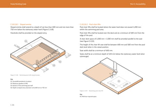
![Dubai Building Code Part C: Accessibility
C 89
C.10.2.9 Recreational buildings and amusement parks
The following requirements and recommendations apply to recreational buildings and
amusements parks.
a) When the nature of the facility requires auditorium seating places, accessible
seating spaces shall be provided. These seating spaces shall conform to the
requirements for auditorium seating spaces in C.10.2.3.
b) Amusement facilities should provide equal use for people of determination.
c) Where providing different amusement facilities in the same recreational building
or amusement park, at least 50% of them should be accessible.
d) Amusement facilities shall have wheelchairs or other personal mobility devices
available for users.
The ADA [Ref. C.2] requirements for the provision of recreational facilities, including
amusement rides, boating facilities, fishing piers, golf facilities and spas, should be
followed.
C.10.2.10 Dining spaces
The following requirements and recommendations apply to dining rooms.
NOTE: An example accessible dining room is shown in Figure C.120.
a) An accessible route shall be provided to at least half of the dining areas.
b) Illumination of a minimum 100 lux shall be provided in at least 10% of the dining
room.
c) Acoustic treatment should be incorporated into dining rooms.
d) At least 10% of the tables shall conform to C.7.3.3 and shall be connected by an
accessible route.
e) An accessible route with a minimum clear width of 1,000 mm shall be provided to
reach the accessible tables, all food service areas, condiments and utensils.
f) Where self-service aisles or counters are provided, all food, condiments and
cutlery shall be within the reach ranges specified in C.5.7. Counters shall conform
to C.7.3.5.
g) For heavy traffic areas and expected two-way passage, a minimum clear passage
of 1,500 mm should be maintained.
h) Space for children strollers and mobility devices shall be provided.
i) A minimum of 10% of seats shall be movable.
Figure C.120 Example of an accessible dining space
≥1,000](https://image.slidesharecdn.com/dubaibuildingcodeenglish2021editionak-231227052107-72adb61a/85/Dubai-Building-Code_English_2021-Edition_AK-pdf-239-320.jpg)
![Dubai Building Code Part C: Accessibility
C 90
C.10.2.11 Kitchen and kitchenettes
C.10.2.11.1 General
Kitchen work surface shall have sections of a maximum depth of 600 mm and
maximum height of 850 mm above finish floor for wheelchair users. These sections
shall be kept clear of floor-mounted cupboards, equipment or legs.
Kitchens shall conform to the clearances specified in either C.10.2.11.2 or
C.10.2.11.3.
C.10.2.11.2 Pass-through kitchen
In pass-through kitchens (see Figure C.121) a minimum clearance of 1,200 mm shall
be provided.
Figure C.121 Clearanceforpass-throughkitchens(modifiedfigurebasedon2010ADAStandardsforAccessible
Design, US Department of Justice 2010, Figure 804.2.1.)
≥1,200
C.10.2.11.3 U-shaped kitchen
In U-shaped kitchens (see Figure C.122) a manoeuvring clearance of 1,500 mm shall
be provided.
Figure C.122 Manoeuvring clearance for U-shaped kitchens (modified figure based on 2010 ADA Standards for
Accessible Design, US Department of Justice 2010, Figure 804.2.2. )
Kitchens should be designed in accordance with the ADA [Ref. C.2] and BS 8300.
Ø1,500 Ø1,500](https://image.slidesharecdn.com/dubaibuildingcodeenglish2021editionak-231227052107-72adb61a/85/Dubai-Building-Code_English_2021-Edition_AK-pdf-240-320.jpg)
![Dubai Building Code Part C: Accessibility
C 91
C.10.2.12 Transport buildings, stations and terminals
C.10.2.12.1 General
This subsection specifies general accessibility requirements for transport related
buildings such as:
a) railway and metro stations;
b) underground railway and rapid transit stations;
c) airports and terminals; and
d) sea terminals.
All platforms and waiting areas shall be connected by accessible routes. Accessible
ticket sales and information counters and seating areas shall be provided. Audio and
visual communication systems shall be provided.
In addition, accessible transportation facilities should be designed in accordance with
the ADA [Ref. C.2] and BS 8300.
C.10.2.12.2 Bus shelters
A bus shelter shall conform to the following requirements.
a) The location of the shelter shall not encroach upon the accessible pedestrian
route, public space or transportation platform.
b) An accessible route shall be provided, free of protruding obstacles on both sides
and with a minimum clear height of 2,100 mm. The route shall have a minimum
clear width of 1,200 mm.
c) There shall be no obstacle between the space covered by the bus shelter and the
transport vehicle.
d) Any glazed walls shall be marked (see C.7.2.3).
e) A minimum of one fixed bench shall be provided.
f) A minimum of one standing support shall be provided, located at a height
between 700 mm and 750 mm above the floor surface and separated from the
wall or vertical enclosure by a minimum of 200 mm.
g) The bus shelter shall have a minimum average illumination of 50 lux, measured at
ground level, during off-service hours. The minimum average illumination shall be
100 lux at the boarding time.
h) The boarding area platform shall have a detectable warning surface.
i) Bus signposts shall not obstruct the accessible routes. No elements shall protrude
below the accessible route clear height requirement.
C.10.2.12.3 Gangways
A gangway shall be used for embarking and disembarking from a berth and to and
from a vessel.
A gangway shall have a maximum gradient of 8%, measured from the vessel or berth
surface to the gangway’s intersection with the berth surface or vessel landing deck
(see Figure C.123).
The width of the gangway should be appropriate to the vessel infrastructure, but
shall be not less than 1,000 mm. It is recommended that this is increased to
1,800 mm for vessels with high pedestrian traffic (see Figure C.124).
The gangway/ramp interface with the berth surface and the vessel landing deck
should be levelled and not exceed a vertical gap of 13 mm chamfered.
A gangway/ramp run with a rise greater than 150 mm should have handrails on both
sides and be of a uniform height above the floor.
The handrails should extend horizontally at least 300 mm beyond the top and
bottom of the gangway/ramp and return to the wall, or post.](https://image.slidesharecdn.com/dubaibuildingcodeenglish2021editionak-231227052107-72adb61a/85/Dubai-Building-Code_English_2021-Edition_AK-pdf-241-320.jpg)
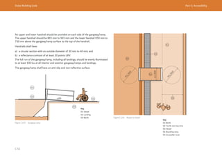
![Dubai Building Code Part C: Accessibility
C 93
C.10.2.13 Sport buildings and exercise rooms
C.10.2.13.1 Exercise rooms
An accessible route shall be provided between equipment in sports and exercise
rooms.
Exercise machines and equipment shall have a clear interaction space. Interaction
spaces shall be provided on the access side of the equipment to allow transfer. One
interaction space can be shared between two pieces of equipment.
C.10.2.13.2 Sport buildings
Accessible sports facilities shall conform to the International Paralympics
Committee’s requirements [Ref. C.3].
For sports facilities, an accessible route shall be provided to connect the boundary of
each activity area.
For court sports, at least one accessible route shall connect both sides of the court.
Where bowling lanes are provided, a minimum of 5%, but not less than 1, shall be on
an accessible route conforming to C.5.
Tiered auditorium seating for sports facilities shall conform to C.10.2.3.
C.10.3 Residential buildings
C.10.3.1 General
Apartment buildings, staff accommodation and labour accommodation buildings shall
have an accessible route for accessing the buildings and residential amenities.
A video doorbell should be provided to facilitate communication with residents for
people of determination.
C.10.3.2 Adaptable units in residential buildings
For new housing developments with more than ten units, a minimum of 2% of the
total units and all common spaces in the building should be adaptable to meet the
accessibility needs and conform to the accessibility requirements of this Part.
This allows low-cost conversion of a house to meet the accessibility needs of any
future residents who are persons of determination.
Volume 1, Section 2 of Approved Document M [Ref C.4] provides guidelines for
designing adaptable accessible units.
All adaptable accessible units in new housing buildings shall conform to the following
requirements.
a) The entrance and internals doors shall conform to C.5.8.
b) Wall-mounted switches and socket outlets shall conform to C.5.7.4.
c) The bathroom shall contain sufficient space clearances to contain a minimum
of one accessible bathtub or shower, accessible sink and water closet with
appropriate space clearances.
d) All walls, ducts and boxings shall be strong enough to support grab rails, seats or
other adaptations that could impose a load up to 1.5 kN/m2
.](https://image.slidesharecdn.com/dubaibuildingcodeenglish2021editionak-231227052107-72adb61a/85/Dubai-Building-Code_English_2021-Edition_AK-pdf-243-320.jpg)
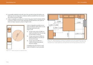
![Dubai Building Code Part C: Accessibility
C 95
C.10.4 Hotel buildings
C.10.4.1 General
All common spaces in hotel establishment shall be accessible.
Accessible hotel rooms should be dispersed between different hotel room types as
necessary in accordance with C.10.4.2 and C.10.4.3.
C.10.4.2 Accessible guest room with mobility features
A minimum number of accessible guest room with mobility features shall be provided
in accordance with Table C.27.
Hotel rooms count Accessible guest rooms with mobility features
50 to 500 2% of total number of rooms
Above 500 1% for additional rooms over 500
Table C.27 Number of accessible guest room with mobility features
Accessible rooms should be located at the lower levels of the hotel, preferably in the
first three guest room floors of the building.
An accessible toilet with grab bars, an accessible shower and a sink shall be provided
(see Figure C.127 and Figure C.128).
50% of the accessible hotel rooms shall contain roll-in showers. The other 50% shall
contain accessible bathtubs (see Figure C.129). An alarm string shall be provided at
the shower or tub.
The accessible rooms shall be provided with audible and visual fire alarms in
accordance with Ch. 8 of UAE FLSC [Ref. C.1].
Controls shall be placed at a height of 400 mm to 1,200 mm, except for those to be
used from the bed. These should be placed within ready reach of occupants. Electric
outlets shall conform to the ranges and locations specified in C.5.7.
A clear route shall be provided to the bed with a minimum clear space of 1,500 mm
× 1,500 mm beside the bed not obstructed by any furniture (see Figure C.130).
The bed shall have a maximum height of 500 mm.
A dressing mirror shall be provided, in which the user can see their reflection from a
distance of 250 mm to 2,000 mm.
Shelves and drawers shall be provided between 700 mm and 1,200 mm from the
floor. Clothes hangers should be provided between 1,100 mm and 1,400 mm above
the floor.
A minimum illumination of 200 lux shall be provided in the guest room area.
Connecting rooms shall have accessible doors.
A viewing device should be provided in the door, with its bottom at a height of
between 900 mm and 1,200 mm.
Changes in level or lip in the washroom or shower area shall be limited to a maximum
5 mm.](https://image.slidesharecdn.com/dubaibuildingcodeenglish2021editionak-231227052107-72adb61a/85/Dubai-Building-Code_English_2021-Edition_AK-pdf-245-320.jpg)
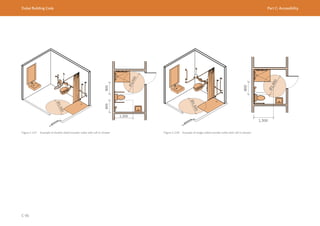
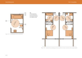
![Dubai Building Code Part C: Accessibility
C 98
C.10.4.3 Accessible guest rooms with communication features
It is recommended that a minimum number of guest rooms with communication
features are provided in accordance with Table C.28. This provision can be separate
from that specified in C.10.4.2 and is not required to conform to C.10.4.2.
Hotel rooms count Accessible guest rooms with communication features
50 to 500 4% of total number of rooms
Above 500 rooms 2% for additional rooms over 500
Table C.28 Number of accessible guest rooms with communication features
Where provided, such a guest room shall:
a) provide compatibility with adaptive equipment used by people with hearing
impairments;
b) contain telephone interface jacks that are compatible with both digital and
analogue signal use;
c) contain visible notification devices to alert room occupants of incoming telephone
calls and a door knock or bell; and
d) contain telephones with volume controls compatible with the telephone system.
The ADA [Ref. C.2] requirements for the provision of guest rooms with
communication features and telephones should be followed.
C.10.5 Education buildings
The following requirements and recommendations apply to education buildings, as
necessary.
a) At building entrances, an accessible route shall be provided, segregated from
vehicle circulation.
b) There should be an accessible route from the bus yard to the building entrance.
c) Seats with different characteristics should be provided dependent on the
students’ needs. Space flexibility shall be provided to guarantee that places can
be provided for wheelchair users, left-handed users, and people of large stature,
limited mobility or breathing, and their communication accessories.
d) Accessible seats at desks shall be removable and the dimensions of the desks
shall allow use by people in wheelchairs.
e) In children’s schools and nurseries, toilets and furniture of the appropriate height
shall be provided (see C.8.3.4.4).
f) Accessible toilets shall be provided for teachers, students and visitors.
g) For students using assistive devices such as computers or optical character
recognition systems, electrical socket outlets should be provided as close as
possible to their seats. The cables between the devices and the socket outlets
shall not obstruct the circulation routes.](https://image.slidesharecdn.com/dubaibuildingcodeenglish2021editionak-231227052107-72adb61a/85/Dubai-Building-Code_English_2021-Edition_AK-pdf-248-320.jpg)
![Dubai Building Code Part C: Accessibility
C 99
C.10.6 Healthcare buildings
In addition to accessibility and design requirements imposed by DHA regulations and
guidelines [Ref. C.5 to Ref. C.15], the following requirements and recommendations
apply to health and social care buildings.
a) Horizontal and vertical circulation should be designed to ease the movement of
beds and gurneys, particularly at changes of directions, at access to rooms from
corridors, and in the dimensions of elevator cabins.
b) Corridors shall have handrails along their entire lengths.
c) All private patient rooms shall be accessible.
d) A minimum of one accessible toilet room for each gender shall be provided in each
department or area.
C.10.7 Business and industrial buildings
All offices, industrial and laboratory facilities including common areas shall be
accessible.
Accessible workstations shall be provided and adapted individually for employees
with functional limitation. Offices, industries and laboratory facilities shall conform to
the following requirements for accessible working areas.
a) The access aisles to workstations shall allow for an accessible route with a
minimum clear width of 1,000 mm.
b) Manoeuvring space shall be provided for persons in wheelchairs to approach the
accessible working area.
c) Work counters used by people of determination shall conform to C.7.3.5.
d) Lighting levels at work areas shall be a minimum of 200 lux.
e) Information on visual displays shall be supplemented by tactile and/or auditory
information, colour contrasted, and located on a glare-free surface.](https://image.slidesharecdn.com/dubaibuildingcodeenglish2021editionak-231227052107-72adb61a/85/Dubai-Building-Code_English_2021-Edition_AK-pdf-249-320.jpg)
![Dubai Building Code Part C: Accessibility
C 100
C.11 Signage and wayfinding accessibility requirement
C.11.1 Wayfinding guidance for accessibility
Wayfinding can be particularly challenging for some people of determination.
EXAMPLE: Someone who has hearing impairment will rely on visual information but
might not be able to hear someone providing directions. Someone who is blind will
not be able to see a directory, but if it is in a predictable location and has information
in a tactile format, they can read it and use sound and even smell to gather more
information about their environment.
It is important to provide wayfinding information in a variety of different formats:
visual, auditory, olfactory and physical. All people use different forms of information
gathering to find their way to their destination, but this is especially important for
people of determination.
Depending on the diversity of the population, visual, acoustic and tactile references
shall be used to guide a person to avoid risks and to reduce confusion.
C.11.2 General requirements
Signs with texts and symbols, visual references and tactile information like high-
embossed characters or Braille text shall be provided.
Signs provided to assist a person in the wayfinding process shall conform to the
following requirements.
a) Colour coding shall be used to differentiate zones or hierarchies of text messages.
Colours that create confusion for the colour-blind should be avoided. For example,
red and green should not be used together where contrasting colours are
required.
b) Signage shall be positioned in a manner that wheelchair users or children can see
it easily.
c) Letters, numbers, symbols and pictographs shall be glare-free and presented in
high reflectance contrast.
d) Signage with text shall be provided in English and Arabic languages.
e) The colour contrast between text and its background shall have a minimum clear
reflectance contrast of 50 points LRV.
f) Accessibility pictograms shall conform to ISO 7000.
The ADA [Ref. C.2] requirements for accessible signage and wayfinding should be
followed.
C.11.3 Tactile maps and signage
C.11.3.1 General features
Tactile maps that offer embossed visual information and acoustic information should
be provided when possible.
Tactile maps should include only essential information: location of services and
routes, and position of elements such as information, main services and toilets.
Terms and concepts used should be easy to understand.
Graphic plane representation (lines, surfaces) should be defined through
embossment, textures and colour contrasts.
The signs and lettering of the map shall be represented through visual contrast
between fonts and background colours. The font size should be a minimum of 20 mm
in a sans serif type font. The information shall also be represented in Braille.
The maximum area of horizontal fixed tactile maps should be 800 mm × 450 mm.
The symbols used shall be clearly differentiated (by form, colour and texture) and
shall be easily associated with their representation.
For complex tactile maps, buttons for oral information shall be provided.](https://image.slidesharecdn.com/dubaibuildingcodeenglish2021editionak-231227052107-72adb61a/85/Dubai-Building-Code_English_2021-Edition_AK-pdf-250-320.jpg)
![Dubai Building Code Part C: Accessibility
C 101
C.11.3.2 Location of tactile maps
When a tactile map is provided, it shall be located
within the accessible route and its location shall be
indicated with a tactile orientation and warning surface.
A map should be located in a well-lit area. Obstacles in
front of a tactile map, such as glass protections, shall
be avoided.
When mounted in a busy public place, a tactile map
shall include sound information.
In a large building or open space for public use (park,
beach), a tactile map shall be located in proximity to
the main entrance area. In a building with more than
one floor, it shall be located near the stairs or the
elevator.
When fixed to a vertical surface, a tactile map shall be
centred between 1,250 mm and 1,750 mm above the
floor. On horizontal or inclined surfaces, the height
shall be between 900 mm and 1,200 mm from the
floor and the inclination shall be between 30º and 45º
from the horizontal level.
C.11.3.3 Raised characters for tactile signage
Tactile signage should be provided. Letters, numbers,
symbols and pictographs should be raised a minimum
of 0.8 mm and should be between 16 mm and 50 mm
high. If a tactile sign is mounted on a wall, its centre
should be at a maximum height of 1,500 mm above the
floor.
Long messages should be avoided for letters and
symbols in high embossment.
Raised characters should be provided for rooms’
or spaces’ identification signage. This signage shall
preferably represent a single icon or character, for
example, the number of an elevator floor, restrooms
icon.
High embossment characters shall be sans serif upper
case.
The tactile signage shall be in high embossment and
not engraved.
Symbol height shall be not less than 30 mm. The
embossment thickness shall be between 2 mm and 5
mm for letters and 2 mm for symbols.
Tactile surfaces shall have a reflectance contrast with
the surrounding surfaces of a minimum 50 points LRV.
C.11.4 Braille
Braille dots shall have a domed or rounded shape (see
Figure C.131).
The indication of an upper case letter or letters shall
only be used before the first word of sentences, proper
nouns and names, individual letters of the alphabet,
initials and acronyms.
Braille characters should be located beneath the
corresponding text, at a minimum distance of 10 mm
from the edge of the sign.
Braille characters shall be separated 10 mm minimum
from any other tactile characters or borders.
The ADA [Ref. C.2] requirements for Braille signage
may be followed.
Figure C.131 Example of Braille characters
Top view
Side view](https://image.slidesharecdn.com/dubaibuildingcodeenglish2021editionak-231227052107-72adb61a/85/Dubai-Building-Code_English_2021-Edition_AK-pdf-251-320.jpg)
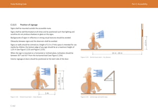
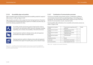
![Dubai Building Code Part D: Vertical transportation
D 3
Door opening time: Period of time (s) measured from
the instant the car doors start to open until they are
800 mm apart.
Door pre-opening time: Time-saving feature allowing
the elevator doors to open in the safe zone while
arriving at landing within 200 mm from the landing
level.
Flight time: Time between the instant the car doors are
locked and the time when the elevator is level at the
next adjacent floor.
Grouping: Elevators in a common lobby serving all or
part of the floors as one group.
Gross area (GA): Floor area within the inside perimeter
of the exterior walls of a building. The measurement
excludes shafts and courtyards, but includes corridors,
stairways, ramps, closets, base of atria (or similar
voids) and the thickness of interior walls, columns or
other features.
Handling capacity (HC5): Average number of
passengers that an elevator or group of elevators can
transport in a period of 5 min.
Handling capacity (HC5%): Percentage of the
occupant load that an elevator group can transport in a
period of 5 min.
High depth: A building more than 7 m below or more
than two basements below the level of exit discharge,
measured in accordance with the UAE FLSC [Ref. D.1].
A more detailed definition is given in UAE FLSC.
D.2 Definitions
D.2.1 Terms
Acceleration: Rate of change of speed or velocity of an
elevator (m/s2
).
Arrival rate: Rate at which passengers arrive for
service by an elevator system, in persons per 5 min or
percentage of building population per 5 min.
Average time to destination: Average period of time (s)
from when a passenger either registers a landing call
or joins a queue until the responding elevator begins to
open its doors at the destination floor.
Average waiting time: Average period of time (s) from
when a passenger either registers a landing call or joins
a queue until the responding elevator begins to open its
doors at the boarding floor.
Boarding floor: Floor that provides entry into a
building, including ground floors, basements, parking,
podium parking, and connections between towers and
car parks at high level.
Capacity factor: Filling rate of an elevator during each
trip, measured in percentage to rated load.
Door closing time: Period of time (s) measured from
the instant the car doors start to close until the doors
are locked.
Door dwell time: Period of time (s) the elevator doors
are open for a fixed length of time (dwell) after an
elevator arrives at a floor. Passengers can then alight or
board. These times are different to the landing calls and
car calls.
High-rise building: Building height greater than or
equal to 23 m and up to 90 m, measured in accordance
with the UAE FLSC [Ref. D.1]. A more detailed
definition is given in UAE FLSC.
Jerk: Rate of change of acceleration (m/s3
).
Occupant load: Total number of persons that might
occupy a building or portion thereof.
Occupiable floor: Floor designed for human occupancy
in which individuals congregate for accommodation,
amusement, work, educational or similar purposes.
Rated capacity: Load (kg and number of people) for
which an elevator has been built and at which it is
designed to operate.
Rated speed (v): Speed (m/s) for which an elevator has
been built and at which it is designed to operate.
Super high-rise building: Building height greater than
90 m, measured in accordance with the UAE FLSC
[Ref. D.1]. A more detailed definition is given in
UAE FLSC.
Swing mode elevator: Elevator that is used for multiple
purposes, e.g. passenger/service, passenger/fire/
service, or fire/service.
Zoning: Virtual separation of the floors in the buildings
based on the elevator groups, such that the elevators
serving one zone do not serve the other zone.](https://image.slidesharecdn.com/dubaibuildingcodeenglish2021editionak-231227052107-72adb61a/85/Dubai-Building-Code_English_2021-Edition_AK-pdf-256-320.jpg)
![Dubai Building Code Part D: Vertical transportation
D 7
D.4 General
Vertical transportation includes elevators, escalators and moving walks. This section
prescribes the international standards to be followed for the safety, reliability and
energy conservation of vertical transportation (VT) systems.
It also sets out the following acceptable design methods for establishing the
minimum number of passenger elevators in different building types:
a) design method 1 – prescriptive design using predefined numbers of passenger
elevators for single occupancy building types (e.g. an apartment building with
associated parking and retail at ground floor) (D.8); and
b) design method 2 – design parameters for use in performance-based vertical
transportation design by VT Consultants (D.9).
The accessibility requirements for vertical circulation, including the provision of
accessible elevators, are defined in C.5.9.3.
D.5 Safety and reliability
Vertical transportation shall be designed, installed, tested, commissioned and
maintained in accordance with one of the following suites of standards:
a) ASME A17 suite of standards; or
b) BS EN 81 suite of standards.
One suite of standards shall be selected for a project. The suites of standards shall
not be used interchangeably.
Elevators required for firefighting shall conform to Section 2.9, Ch. 2 and Section
3.9, Ch. 3 respectively of UAE FLSC [Ref. D.1], in addition to the chosen suite of
standards.
In addition, enhanced handrail protection shall be provided at the entry to escalators
and moving walks as shown in Figure D.1.
Figure D.1 Escalator with enhanced protection to handrail](https://image.slidesharecdn.com/dubaibuildingcodeenglish2021editionak-231227052107-72adb61a/85/Dubai-Building-Code_English_2021-Edition_AK-pdf-260-320.jpg)
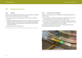
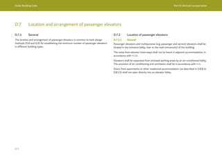
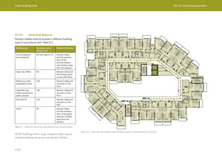
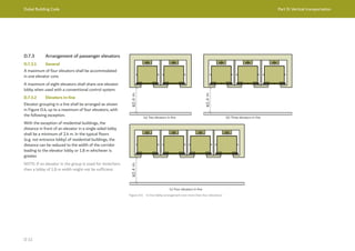
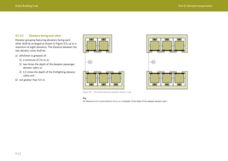
![Dubai Building Code Part D: Vertical transportation
D 13
D.8 Design method 1: prescriptive design using predefined numbers of passenger elevators
D.8.1 General
Design method 1 allows designers to establish the minimum number of passenger
elevators required for different single-occupancy building types, based on the
following parameters:
a) building type;
b) population;
c) number of floors occupied by people;
d) number of boarding floors;
e) elevator grouping.
NOTE 1: Design method 1 is appropriate for single occupancy buildings with
associated facilities such as parking or ground floor retail. Design method 2 is
required for mixed use buildings such as a tower comprising 50% hotel and 50%
office.
NOTE 2: The minimum number of passenger elevators can be influenced by other
parameters. It is the design team’s responsibility to include elevators for other
services, not limited to firefighting elevators (see Section 2.9, Ch. 2 of
UAE FLSC [Ref. D.1]), evacuation elevators (see Section 3.9, Ch. 3 of
UAE FLSC [Ref. D.1]), service elevators (D.8.2) and waste elevators, as required
by building operators, the DBC and the Authorities.
NOTE 3: Design method 2 is required for buildings whose height or population
exceeds those given in the method 1 tables.
NOTE 4: Report templates for design method 1 and design method 2 are given in
D.10.1 and D.10.2. A summary of the minimum information required in the design
method 2 report is given in D.10.3.
Firefighting and service elevators are permitted to be used as passenger elevators
provided that they are located within a group of passenger elevators.
D.8.2 Service elevators
D.8.2.1 Number of service elevators
The minimum number of service elevators serving all floors shall be selected using
Table D.2. Any additional elevators to meet the design intent or the requirements of
relevant Authorities shall be included as necessary.
Any authority requirement for clean and dirty elevators shall be met accordingly.
Building type Classifications Minimum Remarks
Residential — One The firefighting elevator or one of the
passenger elevators could be used as
a service elevator. Where a passenger
elevator is used as a service elevator,
scheduled operation for service mode is
required.
Hotel 1- and 2-star One For keys more than 250, add one elevator
for every 200 keys.
3-star Two —
4- and 5-star Two For keys more than 500, add one elevator
for every 200 keys.
Hotel apartment — One —
Office — One The firefighting elevator or one of the
passenger elevators could be used as
a service elevator. Where a passenger
elevator is used as a service elevator,
scheduled operation for service mode is
required.
Retail/shopping
centres/malls
— One For buildings with more than 75 outlets,
add one elevator for every 100 retail
outlets.
NOTE: Minimum and recommended specifications for service elevators in different buildings types are
given in D.8.8 to D.8.18.
Table D.2 Number of service elevators](https://image.slidesharecdn.com/dubaibuildingcodeenglish2021editionak-231227052107-72adb61a/85/Dubai-Building-Code_English_2021-Edition_AK-pdf-266-320.jpg)
![Dubai Building Code Part D: Vertical transportation
D 14
D.8.2.2 Rated speed
The rated speed of service elevators shall be selected using Figure D.6. Where
a service elevator is grouped with passenger elevators, the rated speed shall be
selected in accordance with D.8.6.
NOTE: It is recommended that service elevators reach the uppermost floor of a
building within 60 s.
Rated
speed
(m/s)
Hotels, hotel apartments
Retail, educational buildings
Travel distance (m)
D.8.3 Firefighting elevators
D.8.3.1 Firefighting elevators
Section 2.9, Ch. 2 of UAE FLSC requires at least one firefighting elevator in a mall, a
multi-storey amusement park and any building which is high-rise, super high-rise or
high depth. Firefighting elevators in super high-rise shall comply with D.8.3.3.
Section 2.9, Ch. 2 of UAE FLSC [Ref. D.1] requires each firefighting elevator to have
access to every floor of the building.
As specified in Ch. 1 Table 1.9 of UAE FLSC [Ref. D.1], either the firefighting elevator
hoistway shall be located within a fire rated shaft constructed of reinforced concrete
(RCC) or all elevators in a common RCC shaft shall be designed as firefighting
elevators.
Firefighting elevators are permitted to be used as passenger elevators provided
that they are located within their own dedicated RCC shaft and are in a group of
passenger elevators (see D.8.7).
Section 2.9, Ch. 2 of UAE FLSC [Ref. D.1] permits firefighting elevators to be used as
service elevators. Firefighting elevators are not permitted to be used as goods lifts.
D.8.3.2 Rated speed of firefighting elevators
The travel time for firefighting elevators to reach the uppermost floor of a building
shall be determined using the suite of standards chosen in D.5.
UAE FLSC [Ref. D.1] requires that firefighting elevators serve all floors of a building.
D.8.3.3 Firefighting elevators in super high-rise buildings
A firefighter’s elevator lobby [minimum gross area (GA) of 9 m2
] shall be provided to
the firefighting elevator in super high-rise buildings (see Section 2.9, Ch. 2 and Table
1.9, Ch. 1 of UAE FLSC [Ref. D.1]). The firefighting elevator lobby shall have direct
access to the firefighting elevator and a fire-rated exit stair.
Where a firefighting elevator has two doors, the second entrance is not required to
open into the firefighting lobby, but it shall be protected by an alternate 1 h
fire-rated lobby.
Figure D.6 Rated speed selection for service elevators
Key
Residential
Hotels, hotel apartments
Offices
Retail, educational buildings](https://image.slidesharecdn.com/dubaibuildingcodeenglish2021editionak-231227052107-72adb61a/85/Dubai-Building-Code_English_2021-Edition_AK-pdf-267-320.jpg)
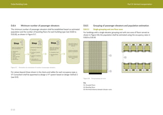
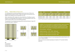
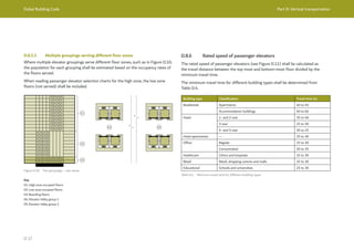
![Dubai Building Code Part D: Vertical transportation
D 18
Figure D.11 Rated speed selection for passenger elevators
Rated
speed
(m/s)
Hotel apartments
Retail, educational buildings
Travel distance (m)
D.8.7 Passenger elevators serving as multipurpose or swing mode
elevators
Some elevators are designed as passenger elevators, while also meeting the
requirements for a firefighting elevator or the functional requirements of a service
elevator. When these elevators are part of a passenger elevator grouping, they shall
be included in calculations for the minimum number of passenger elevators.
Figure D.12 shows a multipurpose elevator in a passenger elevator grouping.
Figure D.12 Passenger, service and fire-fighting elevator in a passenger elevator grouping
Key
01: Firefighting passenger-service elevator
Table 1.9, Ch. 1 of UAE FLSC [Ref. D.1] requires that the firefighting elevator is
located within its own fire-rated RCC shaft.
Key
Residential
Hotels, hotel apartments
Offices
Retail, educational buildings](https://image.slidesharecdn.com/dubaibuildingcodeenglish2021editionak-231227052107-72adb61a/85/Dubai-Building-Code_English_2021-Edition_AK-pdf-271-320.jpg)
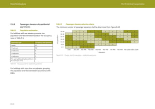
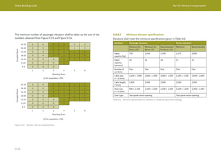
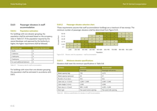
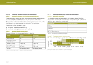
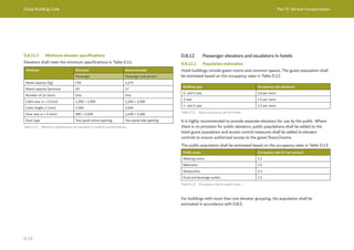
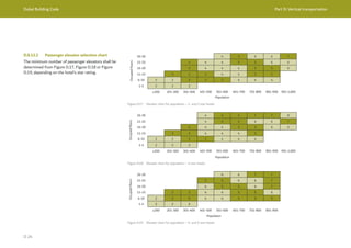
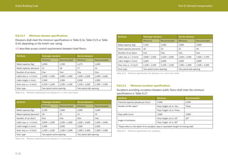
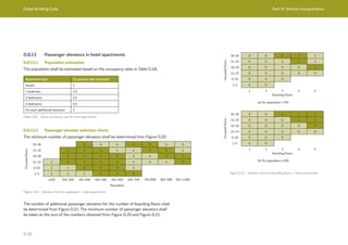
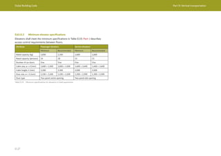
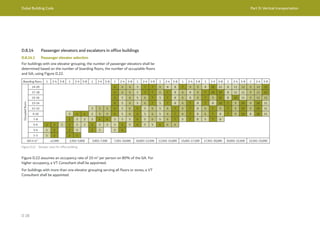
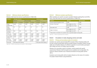
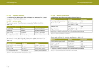
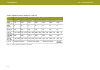
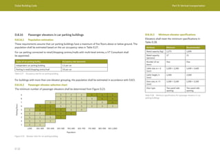
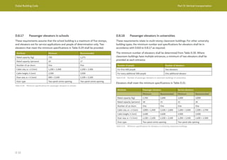
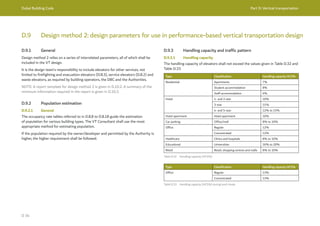
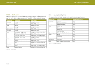
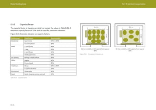
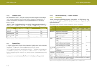
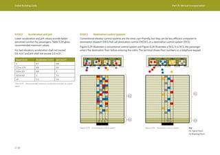
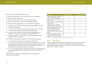
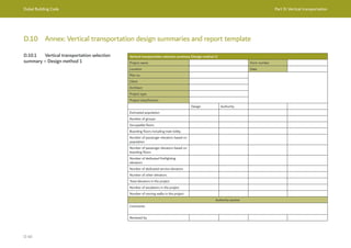
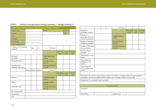
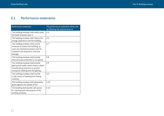
![Dubai Building Code Part E: Building envelope
E 3
E.2 Definitions
E.2.1 Terms
Building elevation: View showing the image of one side
of the building. A flat representation of one façade.
Building envelope: Physical barrier between the
exterior and the conditioned environment of a building
to resist air, water, moisture, heat, cold, light, and noise
transfer. For an air-conditioned building, the building
envelope comprises the elements of a building that
separate conditioned spaces from the exterior. Crown
extensions to the façade to cover plant screen cladding
are part of the building envelope. The building envelope
does not include the physical barrier below ground.
Building maintenance unit: Permanently installed
unit that provides easy and safe access to the building
envelope for maintenance, inspections and cleaning.
Containment: Glass barrier resisting penetration and
preventing people from falling even after failure or
breakage.
Damp-proof course: Layer of waterproof material or
construction in the wall of a building near the ground,
primarily to prevent rising damp.
Damp-proof membrane: Material applied to prevent
moisture transmission.
Drained air space: Air layer within a wall that allows
any entering water or moisture to be drained out.
Glazed element: Individual element within a building
envelope that lets in light, including windows, plastic
panels, clerestories, skylights, doors that are more than
one half glass, and glass block walls.
Glazing: Glass that is installed as one of the
components of a wall, floor, ceiling or roofing system.
Gross wall area: Area of the wall that provides the
thermal barrier of the building. It includes the solid
area and any openings in the wall, such as doors
or windows. It is the actual measured area, not the
projected area on a drawing.
Groundwater pressure: Pressure of groundwater held
within a soil or rock, in gaps between particles.
Guardrail: Vertical protective barrier erected along
elevated walking surfaces, exposed edges of stairways,
balconies and similar areas that minimizes the
possibility of fall from elevated surfaces to lower level.
High-rise building: Building height greater than or
equal to 23 m and up to 90 m, measured in accordance
with the UAE FLSC [Ref. E.1]. A more detailed
definition is given in UAE FLSC.
Interstitial condensation: Condensation which occurs
within or between layers of a construction.
Light transmittance: Percentage of incident light
that passes through the glazed elements. When this
percentage increases, the amount of daylight that
passes into the building will increase.
Low-rise building: Building height less than or up to
15 m, measured in accordance with the UAE FLSC
[Ref. E.1]. A more detailed definition is given in
UAE FLSC.
Manifestation: Clear markings on transparent glazing
to enable occupants to see the glazing as a hazard to
be avoided.
Mid-rise building: Building height greater than 15 m
but less than 23 m, measured in accordance with the
UAE FLSC [Ref. E.1]. A more detailed definition is
given in UAE FLSC.
Moisture: Water or other liquid diffused in a small
quantity as vapour, within a solid, or condensed on a
surface.
Mould: Type of fungus that grows on damp or decaying
material surfaces.
Operational forces: Forces sustained by the building
envelope during operation of the building, e.g. impact
from equipment or occupants.
Rope access or abseiling: Form of work positioning
that allows rope access technicians to descend,
ascend and traverse ropes for access and work while
suspended by their harness.
Shading coefficient (SC): Ratio of solar heat gain at
normal incidence through glazing to that occurring
through an approximately 3 mm thick clear float glass.](https://image.slidesharecdn.com/dubaibuildingcodeenglish2021editionak-231227052107-72adb61a/85/Dubai-Building-Code_English_2021-Edition_AK-pdf-298-320.jpg)
![Dubai Building Code Part E: Building envelope
E 4
Shading device: Projecting fixture that extends outside
the external wall of any building, or a cover (such as
a louver), to protect any door or window from rain or
solar effect.
Skylight or overhead glazing: Glass or other
transparent or translucent glazing material installed at
a slope of 15° or more from vertical.
Solar reflectance index (SRI): Index that combines
reflectivity and emissivity, measuring a material’s
ability to reject solar heat. SRI is defined such that a
standard black (reflectance 0.05 and emittance 0.90) is
0 and a standard white (reflectance 0.80 and emittance
0.90) is 100. Materials with higher SRI absorb less heat
and can reduce heat island effect.
Solid metal panels: factory manufactured panel
consisting of solid metal skin or skins without a core.
Solid metal panels could be aluminium, steel, copper,
zinc, stainless steel, titanium, etc.
Surface condensation: Condensation which occurs on a
visible surface within a building.
Super high-rise building: Building height greater than
90 m, measured in accordance with the UAE FLSC
[Ref. E.1]. A more detailed definition is given in
UAE FLSC.
Thermal bridge: Component or assembly of
components penetrating through an otherwise
continuous thermal line through which heat is
transferred at a substantially higher rate than through
the surrounding envelope areas. Examples could be a
metal fastener, concrete beam, balcony slab or column.
Thermal insulation: Materials/products or the
methods and processes used to reduce heat transfer.
Heat energy can be transferred by conduction,
convection or radiation. The flow of heat can
be delayed by addressing one or more of these
mechanisms and is dependent on the physical
properties of the material employed to do this.
Thermal transmittance: Rate of transfer of heat
through a material(s) or assembly, expressed as a
U-value.
Vapour resistance layer: Material layer within a wall or
roof build-up with a high resistance to moisture vapour.
Window-to-wall ratio (WWR): Percentage determined
by dividing the glazed area by the total external wall
area of the building envelope. WWR can be calculation
per orientation or per entire building.](https://image.slidesharecdn.com/dubaibuildingcodeenglish2021editionak-231227052107-72adb61a/85/Dubai-Building-Code_English_2021-Edition_AK-pdf-299-320.jpg)
![Dubai Building Code Part E: Building envelope
E 9
E.4.1.6 Deflection
Under the action of the most onerous combination of loads, the deflections of
building envelope components shall be limited such that no defect occurs, and
deflections are fully recovered after removal of loads.
The allowable limit deflection shall be determined by material properties, the distance
between points of attachment and the methods of attachment.
NOTE: The deflections given in Table E.1 are generally acceptable in line with Part 3
of the CWCT Standard for systemised building envelopes [Ref. E.2].
Component Measurement Maximum deflection
Storey-height assemblies,
other than masonry
Between points of
attachment to structure
1/200 for span ≤ 3,000 mm
5 mm + 1/300 for
3,000 mm < span < 7,500 mm
1/250 for span ≥ 7,500 mm
Opaque infill panels
in secondary framing,
excluding glass
Between points of support 1/360 for brittle material such as stone
1/90 for non-brittle materials such as
aluminium or steel
Manufacturer recommendation shall also
be sought.
Framing containing glass:
Single glass
Insulating glass units
Between ends of frame
Between ends of unit
1/125 span of member
1/175 span of double-glazed unit
Manufacturer recommendation shall also
be sought.
Table E.1 Maximum recoverable deflection under design load
Deflection limits of main structural elements are given in F.8.
E.4.1.7 Fixings
Fixings to secure the building envelope shall be selected based on the proven
performance of the fixing. Manufacturer test data is generally determined using a
European technical assessment (ETA), a British Standard (BS), a European Norm
(EN) or an ASTM International (ASTM) standard.
The strength of fixings shall be selected based on tests using materials
representative of the material into which the fixing is to be anchored, taking account
of any inherent weaknesses that might affect the strength of the fixing (e.g. cracks in
concrete due to shrinkage and flexure, or voids in masonry construction).
The design of any component shall address the consequences of failure of any
individual fixing.
Fixings shall not be welded.
E.4.2 Structural use of glass
Glass used structurally, or glass that is not supported by load-bearing framing or that
is providing in-plane restraints to components, shall be designed with redundancy
in the system. The redundancy shall be such that if failure or breakage of the glass
occurs, the loading is shared by adjacent components.
NOTE: The Institution of Structural Engineer’s report on structural use of glass in
buildings [Ref. E.3] gives further guidance.
E.4.3 Structural use of silicone
The structural use of silicone in the building envelope shall be in accordance with
ETAG 002 [Ref. E.4].](https://image.slidesharecdn.com/dubaibuildingcodeenglish2021editionak-231227052107-72adb61a/85/Dubai-Building-Code_English_2021-Edition_AK-pdf-304-320.jpg)
![Dubai Building Code Part E: Building envelope
E 10
E.4.4 Materials
Building envelope materials and components shall meet the requirements given in F.6
and IBC [Ref. E.5], Section 1404, Section 1405 and Ch. 23 to Ch. 26.
The properties of glass used in the structural design shall be in accordance with
ASTM E1300.
E.4.5 Impact resistance
The building envelope shall be capable of withstanding applied or transferred impacts
that might occur during normal use (whether accidental, e.g. an object being kicked,
or deliberate, e.g. during maintenance) without sustaining damage that is not
repairable and without deterioration of its performance.
The test energy impacts for opaque areas should be not less than those given in
Table E.2, in accordance with CWCT TN 75 [Ref. E.6].
Soft and hard body testing shall follow the procedures in CWCT TN 76 [Ref. E.7].
Areas of
exposure
Description Soft body Hard body
Safety Serviceability Safety Serviceability
Areas within
1.5 m of ground
or adjacent
finished floor
level (FFL)
Area accessible to the
public and building users.
Chance of accident
occurring and of misuse.
500 J 120 J 10 J 10 J
Other accessible areas.
Some chance of accident
occurring or of misuse.
500 J 120 J 10 J 6 J
Areas between
1.5 m to 6 m
above ground
or above
adjacent FFL
Area liable to impacts
from thrown or kicked
objects.
Might also be subject
to impact during
maintenance which
might impose a higher
impact energy.
350 J 120 J 10 J 6 J
Areas more
than 6 m above
ground or
above adjacent
FFL
Area mainly subject
to impact during
maintenance which
might impose a higher
impact energy.
350 J 120 J 3 J 3 J
Table E.2 Exposure categories and minimum impact test energy for opaque areas](https://image.slidesharecdn.com/dubaibuildingcodeenglish2021editionak-231227052107-72adb61a/85/Dubai-Building-Code_English_2021-Edition_AK-pdf-305-320.jpg)
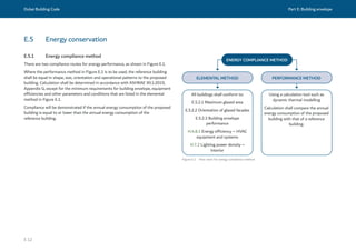
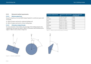
![Dubai Building Code Part E: Building envelope
E 14
E.5.2.3 Building envelope performance
E.5.2.3.1 Non-glazed elements
With the exception of non-conditioned enclosed parking areas, the average thermal
transmittance for external walls, roofs, and exposed floors (the underside of the floor
is exposed to ambient conditions) shall not exceed the values in Table E.4 and
Figure E.3.
Figure E.3 Thermal transmittance for non-glazed elements of roof, external wall and exposed floor
≤0.57 W/m2
K
1 m
≤0.57 W/m2
K
≤0.3 W/m2
K
Table E.4 Thermal transmittance for non-glazed elements of roof, external wall and exposed floor
Element Average thermal transmittance (W/m2
K)
Roof ≤0.3
External wall and exposed floor ≤0.57
While the U-value for external walls can be achieved using aerated concrete blocks,
the use of insulation for the entire building envelope is recommended. Insulation
materials shall conform to Sections 4 to 7, Ch. 1 of UAE FLSC [Ref. E.1].
For the floor area that is in contact with the ground, the thermal transmittance
requirement shall be achieved by installing 1 m of perimeter insulation as shown in
Figure E.3.](https://image.slidesharecdn.com/dubaibuildingcodeenglish2021editionak-231227052107-72adb61a/85/Dubai-Building-Code_English_2021-Edition_AK-pdf-309-320.jpg)
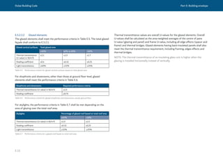
![Dubai Building Code Part E: Building envelope
E 16
01
02
01
02
Key
01: Vertical shading
02: Horizontal shading
E.5.3 Shade effect calculation
The use of external shading is recommended. The impact of external shading
(where used) and adjacent buildings can be taken into account when calculating
external load criteria. Examples of shading devices are shown in Figure E.4.
Figure E.4 Examples of shading arrangements
The impact of external shade factors on the building’s thermal load shall be
calculated when the performance method (see E.5.1) is used to verify energy
compliance.
E.5.4 Thermal bridges
For all new air-conditioned buildings, thermal bridges shall be either eliminated
or insulated to reduce the amount of heat transfer. Thermal bridging can occur at
connection points between concrete or steel beams, external walls and columns, and
around doors and windows (see Figure E.5).
NOTE: The BRE publication on assessing the effects of thermal bridging at junctions
and around openings [Ref. E.8] gives further details.
Figure E.5 Example of linear thermal bridge in buildings](https://image.slidesharecdn.com/dubaibuildingcodeenglish2021editionak-231227052107-72adb61a/85/Dubai-Building-Code_English_2021-Edition_AK-pdf-311-320.jpg)
![Dubai Building Code Part E: Building envelope
E 17
E.5.5 Durability
The building envelope shall be designed and specified to limit degradation due to
environmental factors throughout the design life of the building.
E.5.6 Sealing of windows and doors
Doors and window frames on the building exterior shall be sealed.
Sealing materials shall conform to Sections 4 to 7, Ch. 1 of UAE FLSC [Ref. E.1]. They
shall also prevent the transmission of air and sound that might occur as a result of
pressure differences across the exterior of the building. Air leakage shall be controlled
in accordance with Part H.
Element SRI value
Steep sloped roofs (slopes steeper than 1:6) ≥29
Flat and low sloped roofs (slopes lower than or equal to 1:6) ≥78
External walls ≥29
Table E.8 Building envelope SRI value requirements
SRI≥29
>1:6
≤1:6
SRI≥78 SRI≥78
SRI≥29
Figure E.6 Illustration of SRI value requirements based on slope of roof
E.5.7 Heat island effect reduction
Opaque building envelope surfaces shall have a solar reflectance index (SRI) value
not less than that shown in Table E.8 and Figure E.6, for a minimum of 75% of the
roof area.](https://image.slidesharecdn.com/dubaibuildingcodeenglish2021editionak-231227052107-72adb61a/85/Dubai-Building-Code_English_2021-Edition_AK-pdf-312-320.jpg)
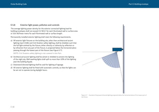
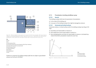
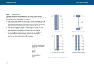
![Dubai Building Code Part E: Building envelope
E 23
E.9 Protection from falling, collision and impact
E.9.1 Protection against impact with glazing
Safety glazing shall be installed in critical locations in doors, side panels and low level
glazing, as shown in Figure E.11 and Figure E.12.
Figure E.11 Safety glazing at door and adjacent areas (© Crown Copyright, 2013. Figure based on Diagram
5.1 of the Building Regulations (2010), Approved Document Part K, 2013 Edition. Contains public sector
information licensed under the Open Government Licence v3.0)
800
01
Figure E.12 Safety glazing at windows (© Crown Copyright, 2013. Figure based on Diagram 5.1 of the Building
Regulations (2010), Approved Document Part K, 2013 Edition. Contains public sector information licensed
under the Open Government Licence v3.0)
Key
01: FFL
Key
01: FFL
In accordance with the Section 5, Ch. 1 of UAE FLSC [Ref. E.1], safety glazing for use
in critical locations shall conform to the minimum classifications in either Table E.9 or
Table E.10.
Critical location Height Classification in test standard
BS EN 12600
Low level areas All heights Class 1
Doors Below 900 mm from FFL Class 2
Doors side panel Above 900 mm from FFL Class 3
Table E.9 Minimum classification for safety glazing
Area of glazing in critical
location (m2
)
Classification in test standard
ANSI Z97.1 CPSC 16 CFR 1201 [Ref. E.9]
≤0.9 A I
>0.9 B I
Table E.10 Minimum classification for safety glazing](https://image.slidesharecdn.com/dubaibuildingcodeenglish2021editionak-231227052107-72adb61a/85/Dubai-Building-Code_English_2021-Edition_AK-pdf-318-320.jpg)
![Dubai Building Code Part E: Building envelope
E 25
E.9.4 Safe opening and closing of windows
Sliding and operable windows shall be located at a height not less than 900 mm from
FFL.
Operable windows shall be restrained to limit the opening to 100 mm to prevent falls.
There shall not be any construction features at the bottom of the window that can be
exploited as a ladder or climbing feature.
Operable windows, skylights and ventilators shall be constructed or equipped such
that they can be opened, closed and adjusted safely. Wherever practicable, the height
of controls or handles shall be in accordance with Part C as indicated in Figure E.14.
If controls or handles cannot be positioned as indicated in Figure E.14, a manual or
electrical means of remote operation shall be provided in that location instead.
Figure E.14 Height of controls or handles
Key
01: FFL
E.9.5 Overhead glazing
Overhead glazing shall be laminated. It shall include a post-breakage containment
system, such that if the glass breaks, the glass is held in place until it can be replaced.
The safety and fragility of overhead glazing shall be determined in accordance with
CWCT TN 66 [Ref. E.10].
Overhead glazing shall be tested in accordance with CWCT TN 67 [Ref. E.11].](https://image.slidesharecdn.com/dubaibuildingcodeenglish2021editionak-231227052107-72adb61a/85/Dubai-Building-Code_English_2021-Edition_AK-pdf-320-320.jpg)
![Dubai Building Code Part E: Building envelope
E 26
E.10 Fire safety
E.10.1 General
The fire safety of the façade and roof elements of the building envelope shall conform
to Ch. 1 of UAE FLSC [Ref. E.1] and the specific requirements of this section.
To prevent external fire spread, the building shall be physically separated from
adjacent plots/buildings or the building envelope shall be fire resistance rated (see
Sections 2.7 and 2.8, Ch. 1 of UAE FLSC [Ref. E.1]).
The requirements for guardrails and balustrades as described in Section 2.17, Ch. 1
of UAE FLSC [Ref. E.1] are superseded by B.4.2.5.2.
The requirements for safety glazing in Sections 5.4.2 to 5.4.4, Ch. 1 of
UAE FLSC [Ref. E.1] are superseded by E.9.
E.10.2 Sprinklers
Sprinklers on balconies, as mentioned by Ch. 9 of UAE FLSC [Ref. E.1], are not
mandated by Dubai Civil Defence (DCD), provided that the materials of construction
of the balcony conform to Ch 1. of UAE FLSC [Ref. E.1].
Sprinklers on the inside of rainscreen/glazing/curtainwall, as mentioned by
Ch. 9 of UAE FLSC [Ref. E.1], are not mandated by DCD.
E.10.3 Spandrels
The fire resistance rated spandrel required by Section 2.8.10, Ch. 1 of
UAE FLSC [Ref. E.1] may be less than 915 mm, provided that the perimeter barrier
system in Section 3.2.4d is tested, certified and listed with the intended spandrel
specifications, complete with installation guidelines.
E.10.4 Fire testing of non-fire resistance rated, non-loadbearing
façades and aesthetic features/mashrabiya
The requirements in Section 4.2.1, Ch. 1 of UAE FLSC [Ref. E.1] shall be met, with
the following amendments.
a) The exceptions listed in Section 4.2.1, Ch. 1 of UAE FLSC [Ref. E.1] are expanded
to include concrete, terracotta, glass, ceramics and mineral wool.
b) In addition to the materials listed in Section 4.2.1, Ch. 1 of UAE FLSC [Ref. E.1],
solid metal panels conforming to E.10.5 may be used.
The requirements in Section 4.5, Ch. 1 of UAE FLSC [Ref. E.1] shall be met, with the
following amendments.
1) Steel flashing is not required around window openings.
2) Flashing shall match the flashing included in the NFPA 285 fire test(s) forming
the basis of the fire safety design(s) of the façade.](https://image.slidesharecdn.com/dubaibuildingcodeenglish2021editionak-231227052107-72adb61a/85/Dubai-Building-Code_English_2021-Edition_AK-pdf-321-320.jpg)
![Dubai Building Code Part E: Building envelope
E 27
Table E.11 Fire test requirements for solid metal panels on non-fire resistance rated and non-load-bearing
building envelope and aesthetic features/mashrabiya
Occupancy and
type of building
Fire testing required for solid
metal panel
Fire testing required for façade assembly
Super high-rise
buildings
High-rise buildings
Malls
Theme parks
Schools
Hospitals
Assembly
Panel shall be tested in the
thickness intended to be used,
including any coatings to
BS EN 13501-1 with pass criteria
A1 or A2-s1-d0.
BS 8414-1 or BS 8414-2
with pass criteria in accordance with
BR 135 [Ref. E.12]
or
NFPA 285 with pass criteria “pass”
or
FM 4881 with pass criteria “pass”
or
ISO 13785-2 with pass criteria “pass”
Low-rise buildings
Mid-rise buildings
Warehouses
Industrial
Panel shall be tested in the
thickness intended to be used,
including any coatings to
BS EN 13501-1 with pass criteria
B-s1-d0.
BS 8414-1 or BS 8414-2
with pass criteria in accordance with
BR 135 [Ref. E.12]
or
NFPA 285 with pass criteria “pass”
or
FM 4881 with pass criteria “pass”
or
ISO 13785-2 with pass criteria “pass”
E.10.5 Solid metal panels
Solid metal panels (including any coatings) shall conform to Sections 4 to 7, Ch. 1
of UAE FLSC [Ref. E.1]. They shall also achieve the fire safety classifications and fire
safety performance criteria shown in Table E.11 to Table E.13 where applicable.
Table E.12 Fire test requirements for solid metal panel on a fire resistance rated exterior wall assembly
Occupancy and
type of building
Fire testing required for solid
metal panel
Fire testing required for façade assembly
Any building with
any height and any
occupancy
Panel shall be tested in the
thickness intended to be used,
including any coatings to
BS EN 13501-1 with pass criteria
A1 or A2-s1-d0.
ASTM E119
with pass criteria 1 h or 2 h or 3 h as per
required fire rating of the wall
or
UL 263
with pass criteria 1 h or 2 h or 3 h as per
required fire rating of the wall
or
BS EN 1364-3
with pass criteria 1 h or 2 h or 3 h as per
required fire rating of the wall
or
BS EN 1364-4
with pass criteria 1 h or 2 h or 3 h as per
required fire rating of the wall](https://image.slidesharecdn.com/dubaibuildingcodeenglish2021editionak-231227052107-72adb61a/85/Dubai-Building-Code_English_2021-Edition_AK-pdf-322-320.jpg)
![Dubai Building Code Part E: Building envelope
E 28
Table E.13 Fire test requirements for solid metal panel in roofing
Applications Exterior fire exposure to
roofing assemblies
Interior or under deck fire exposure to
roofing assemblies
Roofing in sprinklered buildings
Roofing in buildings protected with fire
suppression systems.
NFPA 256
with pass criteria Class B
or
ASTM E108
with pass criteria Class B
or
BS EN 13501-5
with pass criteria Class BROOF(t4)
or
UL 790
with pass criteria Class B
Roofing in non-sprinklered buildings
Roofing in buildings without fire
suppression.
Roofing in buildings less than 6 m from an
adjacent building.
Roofing in malls, assembly, hospitals and
educational.
NFPA 276
with pass criteria Class 1
or
ASTM E108
with pass criteria Class A
or
BS EN 13501-5
with pass criteria Class BROOF(t4)
or
UL 790
with pass criteria Class A
or
FM 4470 or FM 4471
with pass criteria “Pass”
FM 4450 with pass criteria Class I
or
UL 1256 with pass criteria "pass"
Structural metal panel roof systems shall be
tested with FM 4471
Roof systems with modified bitumen and
other types of membrane roof systems shall
be tested with FM 4470
E.10.6 Fire resistance rated glazing
assemblies
Fire resistance rated glazing assemblies shall conform
to Sections 5.3 and 5.4, Ch. 1 of UAE FLSC [Ref. E.1].
E.10.7 Roof assemblies
Roof assemblies shall conform to the performance
requirements of Section 6, Ch. 1 of
UAE FLSC [Ref. E.1]. They shall have the fire resistance
periods specified in Section 6, Ch. 1 of
UAE FLSC [Ref. E.1].
E.10.8 Roof and façade assemblies
Materials used both on the façade and the roofing shall
be fire tested in both configurations in accordance with
Sections 4 and 6, Ch. 1 of UAE FLSC [Ref. E.1].
If the roof is not horizontal then it shall be fire tested
as a façade system in accordance with Section 4, Ch. 1
of UAE FLSC [Ref. E.1].](https://image.slidesharecdn.com/dubaibuildingcodeenglish2021editionak-231227052107-72adb61a/85/Dubai-Building-Code_English_2021-Edition_AK-pdf-323-320.jpg)
![Dubai Building Code Part E: Building envelope
E 29
E.10.9 Signboards and billboards
Signboards and billboards on façades shall conform to Section 4, Ch. 1 of
UAE FLSC [Ref. E.1].
When the cumulative surface area of signboards/billboards on a façade is greater
than 50 m2
, or the signboard/billboard straddles more than one storey, then they
shall be fire tested as part of the façade system in accordance with Section 4, Ch. 1 of
UAE FLSC [Ref. E.1].
E.10.10 Solar panels
Photovoltaic (PV) cells or panels installed on roofs or façades shall conform to
Section 2.2, Ch. 14 of UAE FLSC [Ref. E.1]. If PV panels are attached to or integrated
with the façade then they shall also be tested in accordance with Section 4, Ch. 1 of
UAE FLSC [Ref. E.1].
In accordance with B.10.2, all outdoor mechanical equipment (including antennas,
rooftop equipment and refuse storage areas) should be concealed from public view by
solid walls, screens, fences, parapets, enclosing structures or landscaping.
E.11 Screening of building equipment](https://image.slidesharecdn.com/dubaibuildingcodeenglish2021editionak-231227052107-72adb61a/85/Dubai-Building-Code_English_2021-Edition_AK-pdf-324-320.jpg)
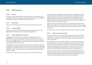
![Dubai Building Code Part E: Building envelope
E 31
E.12.6 Protection from impact on building envelope
Hard or sharp components of the maintenance equipment shall be covered with soft
protection to prevent the building envelope from being impacted.
The energy impact that the maintenance equipment or operator might exert on
the building envelope shall be calculated. The building envelope shall be capable of
withstanding applied or transferred impacts that might occur during maintenance
without sustaining damage that is not repairable and without deterioration of its
performance.
NOTE: CWCT TN 96 [Ref. E.13] gives guidance to assess cradle and suspended
access equipment loads.
E.12.7 Health and safety
E.12.7.1 Rope access
Rope access systems shall follow safety guidelines such as IRATA [Ref. E.14].
A back-up fall arrest system shall be provided.
Back-up fall arrest system may be achieved by using two ropes: a working line and a
safety line.
E.12.7.2 Power-operated systems
Means shall be provided to traverse all carriages and their suspended equipment to
a safe area for maintenance and storage. The working platform shall, as part of its
normal operation, be capable of being lowered to a safe surface for access and egress
of the personnel. The working platform shall be provided with a safe means of access
and egress to the lower safe surface.
The following non-exhaustive list of safety features shall be included before
installation of building maintenance unit/glass cleaning cradle:
a) provisions in case of power failure;
b) overload safety device;
c) wire rope equalizer limit switch;
d) emergency stop;
e) secondary brake with over-speed protection (mechanical);
f) slack rope device;
g) lanyard restraint trip assembly;
h) rotational slew limits;
i) factor of safety for wire rope;
j) cradle details (i.e. anti-collision bar, handrail/mid rail height, etc.);
k) horizontal traversing wheel locking device; and
l) working environment (i.e. weather conditions such as temperature, humidity, wind
speed, etc.).](https://image.slidesharecdn.com/dubaibuildingcodeenglish2021editionak-231227052107-72adb61a/85/Dubai-Building-Code_English_2021-Edition_AK-pdf-326-320.jpg)
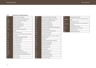
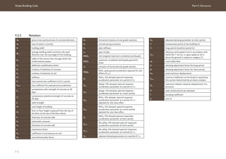
![Dubai Building Code Part F: Structure
F 6
F.3 References
F.3.1 Essential references
F.3.1.1 General
ASCE/SEI 7-16, Minimum design loads and associated
criteria for buildings and other structures
ASCE 37, Design loads on structures during
construction
ASCE 41, ASCE 41, Seismic evaluation and retrofit of
existing buildings
ISO 10137, Bases for design of structures –
Serviceability of buildings and walkways against
vibrations
Ref. F.1 UFC 4-023-03:2009. Design of buildings to
resist progressive collapse, with change 3, revision
2016. Whole building design guide [online database].
Available from: www.wbdg.org.
Ref. F.2 UAE MINISTRY OF INTERIOR GENERAL
COMMAND OF CIVIL DEFENCE, 2018. UAE Fire and
Life Safety Code of Practice (UAE FLSC). United Arab
Emirates: Ministry of Interior General Command of
Civil Defence.
Ref. F.3 INTERNATIONAL CODE COUNCIL, 2018.
International Building Code. Washington: International
Code Council.
Ref. F.4 National Centre for Meteorology and
Seismology [online database]. Available from:
www.ncm.ae/en/climate-reports-yearly.html?id=26.
Ref. F.5 KILPATRICK, J., SIFTON, V. and GIBBONS
M., 2020. Dubai wind design parameters review. Final
Report. RWDI.
Ref. F.6 KWOK, K.C.S., BURTON, M.D. and
ABDELRAZAQ, A.K., 2015. Wind-induced motion of
tall buildings: Designing for habitability. Virginia: ASCE.
Ref. F.7 BRITISH GEOLOGICAL SURVEY, 2006.
Geology and geophysics of the United Arab Emirates.
London: British Geological Survey.
Ref. F.8 CRSI, 2008. Design handbook, 10th edition.
Concrete Reinforcing Steel Institute.
Ref. F.9 IDRISS, I.M. and BOULANGER, R.W., 2008. Soil
liquefaction during earthquakes. California: Earthquake
Engineering Research Institute.
F.3.1.2 Concrete
ACI 89-S15, Shrinkage cracking in fully restrained
concrete members
ACI 117-10, Specification for tolerances for concrete
construction and materials and commentary
ACI 209.2R, Guide for modelling and calculating
shrinkage and creep in hardened concrete
ACI 215R, Considerations for design of concrete
structures subjected to fatigue loading
ACI 216.1, Code requirements for determining fire
resistance of concrete and masonry construction
assemblies
ACI 224R, Control of cracking in concrete structures
ACI 315R, Guide to presenting reinforcing steel design
details
ACI 318-19, Metric building code requirements for
structural concrete
ACI 363R-10, Report on high-strength concrete
ACI 408.2R, Report on bond of steel reinforcing bars
under cyclic loads
ACI 435R, Control of deflection in concrete structures
BS EN 206, Concrete – Specification, performance,
production and conformity
BS 8500-1:2015, Concrete – Complementary British
Standard to BS EN 206 – Part 2: Method of specifying
and guidance for the specifier
Ref. F.10 CIRIA C766, 2018, Control of cracking caused
by restrained deformation in concrete. 3rd edition.
London: CIRIA.
Ref. F.11 TR43, 2005. Post-tensioned concrete floors
– Design handbook, 2nd Edition. Camberley: Concrete
Society.
Ref. F.12 PRECAST/PRESTRESSED CONCRETE
INSTITUTE, 2017. Design handbook – Precast and
prestressed concrete, 8th edition and errata vol. I and
II, 2019. Chicago: PCI.
Ref. F.13 APPLIED TECHNOLOGY COUNCIL, 1999.
Design Guide 1 – Minimizing floor vibration.
California: ATC.](https://image.slidesharecdn.com/dubaibuildingcodeenglish2021editionak-231227052107-72adb61a/85/Dubai-Building-Code_English_2021-Edition_AK-pdf-332-320.jpg)
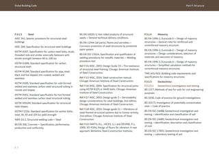
![Dubai Building Code Part F: Structure
F 9
F.3.2 Further reading
F.3.2.1 Concrete
ACI 301, Specifications for structural concrete
ACI 350, Code requirements for environmental
engineering concrete structures
F.3.2.2 Geotechnics
ACI 543R, Guide to design, manufacture, and
installation of concrete piles
CIRIA, 2017. C760, Guidance on embedded retaining
wall design. London: CIRIA.
INSTITUTION OF CIVIL ENGINEERS, 2016.
Specification for piling and embedded retaining walls
(SPERWall), 3rd edition. London: ICE Publishing.
F.3.2.3 Seismic
NA to BS EN 1998-1, UK National annex to Eurocode
8 – Design of structures for earthquake resistance –
General rules, seismic actions and rules for buildings
Ref. F.22 MALHOTRA, P.K., 2020. Seismic design
ground motion parameters for Dubai. Report Number:
SMI-93-2019 Revision 6, Prepared for Dubai
Municipality.
Ref. F.23 IRFAN, M., KHAN, Z.H., EL-EMAM, M. and
ABDALLA, J., 2012. Seismic Hazard Assessment and
Spectral Accelerations for United Arab Emirates. 15th
World Conference on Earthquake Engineering, Lisbon:
Portugal.
Ref. F.24 SHAMA, A.A., 2011. Site specific probabilistic
seismic hazard analysis at Dubai Creek on the west
coast of the UAE. Earthquake Engineering and
Engineering Vibration. 10(1). pp. 143- 52.
Ref. F.25 ALDAMA-BUSTOS, G., BOMMER, J.J.,
FENTON, C.H. and STAFFORD, P.J., 2009. Probabilistic
seismic hazard analysis for rock sites in the cities of
Abu Dhabi and Ra’s Al Khaymah, United Arab Emirates.
Georisk: Assessment and management of risk for
engineered systems and geohazards, 3(1), pp. 1-29.
Ref. F.26 PASCUCCI, V., FREE, M.W. and LUBKOWSKI,
Z.A., 2008. Seismic hazard and seismic design
requirements for the Arabian Peninsula Region. 14th
World Conference on Earthquake Engineering, 2008.
Beijing: China.
Ref. F.27 MUSSON, R.M.W., NORTHMORE, K..J,
SARGEANT, S.L., PHILLIPS, E.R., BOON, D., LONG,
D., MCCUE, K. and AMBRASEYS, N.N., 2006. The
geology and geophysics of the United Arab Emirates.
Geological Hazards, British Geological Survey, volume
4, Keyworth.
Ref. F.28 SIGBJORNSSON, R., and ELNASHAI, A.S.,
2006. Hazard assessment of Dubai, United Arab
Emirates, for close and distant earthquakes. Journal of
Earthquake Engineering, 10(5), pp. 749-773.
Ref. F.29 ABDALLA, J.A., and AL-HOMOUD, A.,
2004. Earthquake hazard zonation of eastern Arabia.
Proceedings of the 13th World Conference on
Earthquake Engineering, Vancouver, Canada, August
1-6, Paper No. 1008.
Ref. F.30 GRÜNTHAL, G., BOSSE, C., SELLAMI, S.,
MAYER-ROSA, D. and GIARDIN, D., 1999. Compilation
of the GSHAP regional seismic hazard for Europe,
Africa and the Middle East. Annali di Geofisica, 42(6),
pp. 1215-1223.
Ref. F.31 AL-HADDAD, M., SIDDIQI, G.H., AL-ZAID, R.,
ARAFAH, A., NECIOGLU, A. and TURKELLI N., 1994.
A basis for evaluation of seismic hazard and design
criteria for Saudi Arabia. Earthquake Spectra, 10(2),
pp. 231-257.
Ref. F.32 BEYER, K. and BOMMER, J.J., 2006.
Relationships between Median Values and between
Aleatory Variabilities for Different Definitions of the
Horizontal Component of Motion. Bulletin of the
Seismological Society of America, 97(5).
Ref. F.33 LUCO, N., 2011. Development of Risk-
Targeted Earthquake Ground Motions for use in ASCE
7. NEHRP Advisory Committee Meeting. Available
at: www.nehrp.gov/pdf/ACEHRMar2011_ASCE7.pdf
[viewed 15 September 2020].
Ref. F.34 MURRIS, R.J., 1981. Middle East:
Stratigraphic evolution and oil habitat. Geologie en
Mijnbouw, 60, pp. 467-486.
Ref. F.35 HANCOCK, P.L., AL KADHI, A. and SHA’AT,
N.A., 1984. Regional joint sets in the Arabian Platform
as indicators of intraplate processes. Tectonics, 3(1),
pp. 27-43.](https://image.slidesharecdn.com/dubaibuildingcodeenglish2021editionak-231227052107-72adb61a/85/Dubai-Building-Code_English_2021-Edition_AK-pdf-335-320.jpg)
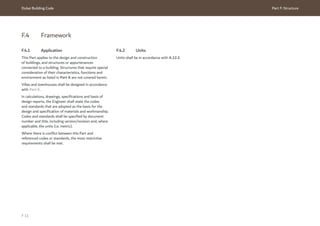
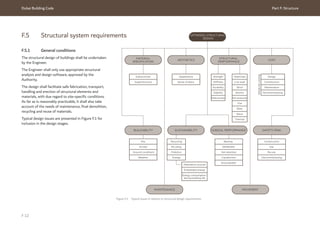
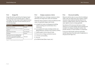
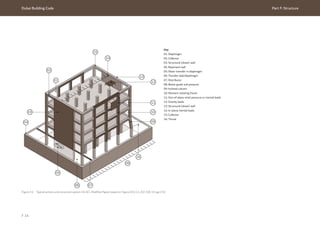
![Dubai Building Code Part F: Structure
F 15
F.5.5 Robustness against disproportionate collapse
Measures shall be taken to ensure that the building is robust and resistant to
disproportionate collapse under the specified load conditions. One of the following
approaches shall be used.
a) Direct design: Explicit consideration of resistance to progressive collapse during
the design process through either:
1) tie forces method (see Figure F.3);
2) alternate path method; or
3) enhanced local resistance method.
Further details on the direct design methods can be found in
UFC 4-023-03 [Ref. F.1].
b) Indirect design: Implicit consideration of resistance to progressive collapse
during the design process through the provision of minimum levels of strength,
continuity, and ductility.
Further details on the indirect design method can be found in Appendix C of
ASCE/SEI 7-16.
It is recommended that the direct design approach is undertaken in accordance with
UFC 4-023- 03 [Ref. F.1], as illustrated in Table F.2.
Table F.2 Risk category and design requirements
Risk category (per table
1.5-1 of ASCE/SEI 7-16)
Design requirement
I No specific requirements.
II Indirect design approach.
OR
Direct design option 1: Tie forces for the entire structure and enhanced
local resistance for the corner and penultimate columns or walls on the
first storey.
OR
Direct design option 2: Alternate path for specified column and wall
removal locations.
III AP for specified column and wall removal locations and enhanced local
resistance for all perimeter first storey columns or walls.
IV Tie forces and alternate path for specified column and wall removal
locations and enhanced local resistance for all perimeter first storey
columns or walls.](https://image.slidesharecdn.com/dubaibuildingcodeenglish2021editionak-231227052107-72adb61a/85/Dubai-Building-Code_English_2021-Edition_AK-pdf-341-320.jpg)
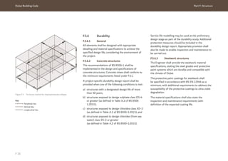
![Dubai Building Code Part F: Structure
F 17
F.5.7 Fire resistance
The construction type and fire resistance rating of structural elements shall
be determined based on the type of building, its height/size and occupancy in
accordance with Section 2, Ch. 1 of UAE FLSC [Ref. F.2].
All proposed fire protection products and systems shall be tested and certified by
accredited laboratories and approved by Dubai Civil Defence (DCD).
The fire resistance rating of the main structural elements shall be taken into account
in the structural design and clearly stated in the structural drawings.
Fire resistance of concrete and masonry elements shall conform to the requirements
of ACI 216.1.
Fire resistance of steel structures shall conform to the requirements of the AISC
Design Guide 19 [Ref. F.14].
F.5.8 Sustainability
Sustainability standards shall be observed when designing the structure, during the
building’s lifecycle.
The design of the permanent works, together with the construction operations
shall fulfil resource efficiency standards in terms of materials. Concrete mixes shall
conform to F.11.
F.6 Materials
F.6.1 General
This section provides the minimum requirements for the design and construction of
building and structural components using reinforced concrete, post-tensioned (PT)
concrete, precast concrete, steel and masonry.
For other materials, such as aluminium, timber, gypsum board, glass and plastic, the
structural requirements stated under Ch. 23 to Ch. 26 of the IBC [Ref. F.3] shall be
followed. These materials shall only be used where also permitted by Sections 2, 4, 6
and 7, Ch. 1 of UAE FLSC [Ref. F.2].
The specification of all constituent materials of the structural system shall be
compatible with the specified codes and clearly detailed in the design documentation.
The design shall take into account how the strength, stiffness and durability of all
materials changes over time.
F.6.2 Structural concrete
F.6.2.1 Design basis
The design of concrete for structural purposes, including plain concrete and concrete
containing non-prestressed reinforcement, prestressed reinforcement or both, shall
conform to the requirements of ACI 318-19 including standards referenced therein.
F.6.2.2 Concrete strength
The concrete used for structural elements shall have compressive strength not less
than fcu = 35 N/mm2
and f’c = 28 N/mm2
.
Concrete for blinding and screeds shall have compressive strength not less
than fcu = 20 N/mm2
.
All concrete in contact with the ground shall be designed for the aggressiveness of
the contact soil (refer to F.5.6.2).](https://image.slidesharecdn.com/dubaibuildingcodeenglish2021editionak-231227052107-72adb61a/85/Dubai-Building-Code_English_2021-Edition_AK-pdf-343-320.jpg)
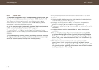
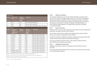
![Dubai Building Code Part F: Structure
F 20
Table F.4 Reinforcement limits requirements
Structural element Reinforcement limits
requirement
Remarks
One-way slab 7.6 of ACI 318-19 -
Two- way slab 8.6 of ACI 318-19 -
Beams 9.6 of ACI 318-19 -
Columns 10.6 of ACI 318-19 -
Walls
11.6 of ACI 318-19
The Engineer should check the effect of creep and
shrinkage.
Diaphragms 12.6 of ACI 318-19 -
Foundations Section 13 of
ACI 318-19
-
The fire resistance of the concrete elements (cover to reinforcing) shall conform to
the reinforcement requirements specified in ACI 216.1.
NOTE: The Engineer and the Contractor are responsible for avoiding reinforcement
congestion that would otherwise lead to poor concrete compaction or similar.
F.6.3 Post-tensioned concrete
F.6.3.1 Design basis
PT concrete elements shall be designed and specified in accordance with ACI 318-19
including standards referenced therein.
NOTE: Further guidance is given in TR43 [Ref. F.11]. The main steps to be followed
are shown in Figure F.4.
CHOOSE
• Structural layout
• Concrete grade
• Member sizes
DETERMINE:
• Loading Tendon profiles
• Force per tendon
• Load to be balanced
• Required pre-stress
• Number of tendons
• Pre-stress losses
CHECK FLEXURAL ADEQUACY AT SLS:
• After all losses
• At transfer of pre-stress
REVISE DESIGN:
• Number and profile of tendons
• Amount of reinforcement
• Floor thickness
• Concrete grade
• Layout
CHECK SERVICEABILITY AT SLS:
• Cracking
• Deflections
• Vibrations
CHECK ULTIMATE CAPACITY:
• Flexure
• Shear
DETAIL STRUCTURE AND
FINALISE DRAWINGS
PERFORM STRUCTURAL ANALYSIS
IF NOT OK
IF NOT OK
IF NOT OK
IF OK
IF OK
IF OK
DESIGN FOR POST-TENSIONED
CONCRETE ELEMENTS
:
Figure F.4 Design flow chart for post-tensioned concrete elements (© The Concrete Society. Post-tensioned
Concrete Floors - Design Handbook, Technical Report 43 2nd Edition, pg.22. The Concrete Society, Camberley,
2005 [Ref. F.11])](https://image.slidesharecdn.com/dubaibuildingcodeenglish2021editionak-231227052107-72adb61a/85/Dubai-Building-Code_English_2021-Edition_AK-pdf-346-320.jpg)
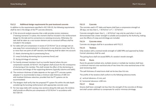
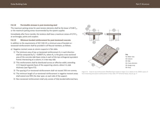
![Dubai Building Code Part F: Structure
F 23
45°
45° 45°
01 02
05
03
04 04
05 05
b) Thermal and shrinkage reinforcement.
1) The minimum thermal and shrinkage
reinforcement shall be in accordance with
ACI 318-19. For slab thicknesses of 200 mm
or less, the minimum reinforcement shall
be provided at the bottom layer. For thicker
slabs, the minimum reinforcement can be split
between top and bottom layers.
2) The bottom reinforcement mesh shall run
through the column location.
c) Integrity reinforcement. At the member supports,
at least one tendon comprising at least two strands
shall pass through the columns or walls. The
following shall be observed.
1) If the tendon is not passing through the
columns or walls, then a minimum amount of
bottom un-tensioned reinforcement shall be
provided for structural integrity.
2) Minimum bottom un-tensioned reinforcement
shall be the lower of either 150% of the
minimum calculated flexural reinforcement,
or (2.1 bw h/fy ) where bw is the width of the
column face through which the reinforcement
passes.
3) Un-tensioned reinforcement bars passing
through the column shall extend beyond the
column or shear cap face by a minimum distance
equal to or greater than the bar development
length.
d) Edge reinforcement.
1) Un-tensioned reinforcement shall be provided
in accordance with ACI 318-19 to resist spalling
and longitudinal edge tension forces induced
by the anchorage devices. The quantity shall be
calculated for the anchorage arrangement. The
effects of abrupt changes in section and the
stressing sequence shall also be included.
2) The area of tension reinforcement (and/or
prestressed tendons) provided parallel to
the slab edge shall resist bending moments
from the ultimate vertical loads calculated
for a continuous slab, spanning “LA”. This
reinforcement shall be evenly distributed across
a width equal to 0.7 LA and shall be continuous
along the edge (see Figure F.6).
Figure F.6 Unstressed areas between tendons requiring reinforcement (© The Concrete Society. Post-tensioned Concrete Floors - Design Handbook,
Technical Report 43 2nd Edition, pg.40. The Concrete Society, Camberley, 2005 [Ref. F.11])
3) The area of reinforcement placed perpendicular
to the slab edge shall be the greater of thermal
and shrinkage minimum reinforcement, or a
quarter of the reinforcement provided parallel
to the edge. It shall be placed evenly between
anchorages and extend the greater of LA or
0.7 LA plus a full anchorage length into the slab.
Key
01- 03: Slab Span LA
04: Unstressed areas
05: Tendons](https://image.slidesharecdn.com/dubaibuildingcodeenglish2021editionak-231227052107-72adb61a/85/Dubai-Building-Code_English_2021-Edition_AK-pdf-349-320.jpg)
![Dubai Building Code Part F: Structure
F 24
> 500
<
500
<
500
01
02
03
04
02
F.6.3.10 Post-tensioned concrete reinforcement
detailing
Reinforcement and PT tendons shall be detailed
in accordance with ACI 318-19 and with the
requirements stipulated herein.
For situations where it is not feasible to place the
prestressing tendons within 0.5 h from the column
face, un-tensioned reinforcement shall be placed to
bridge the vertical force from the adjacent tendon to
the columns, as shown in Figure F.7 and Figure F.8.
At least one reinforcement bar should pass over the
column. Reinforcement bars should be positioned
below the pre-stressed tendon (see Figure F.8).
These un-tensioned reinforcement bars shall extend
beyond the column or shear cap face by a minimum
distance equal to or greater than the bar development.
Figure F.7 Additional reinforcement required where tendons are not within 0.5 h from the column (© The Concrete Society. Post-tensioned Concrete
Floors - Design Handbook, Technical Report 43 2nd Edition, pg.42. The Concrete Society, Camberley, 2005 [Ref. F.11])
Key
01: Reinforcement bars.
02: Tendons
03: Full anchorage length
04: Column](https://image.slidesharecdn.com/dubaibuildingcodeenglish2021editionak-231227052107-72adb61a/85/Dubai-Building-Code_English_2021-Edition_AK-pdf-350-320.jpg)
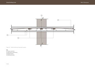
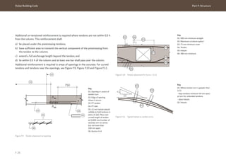
![Dubai Building Code Part F: Structure
F 27
F.6.4 Precast concrete
F.6.4.1 Design basis
Precast concrete elements, including those that
are normally reinforced and/or prestressed, shall
be designed and specified in accordance with this
subsection, supplemented by the requirements given
in ACI 318-19 and Precast/prestressed Concrete
Institute (PCI) design handbook [Ref. F.12].
F.6.4.2 Concrete
Reinforcement and prestressed strands shall conform
to the requirements stated under Section 1 of the PCI
design handbook [Ref. F.12].
The concrete used for precast structural elements shall
have a compressive strength of not less than
fcu = 40 N/mm2
measured at 28 days. A lower strength
may only be used if its suitability can be demonstrated
and it is accepted by the Authority.
The minimum transfer strength (when prestress force
is transferred to the concrete) shall be 25 N/mm2
,
unless the adequacy of a lower strength can be
demonstrated in the design, making sure the effects of
creep and shrinkage are included.
F.6.4.3 Concrete mixes
Concrete mix designs shall be in accordance with
F.6.2.3.
F.6.4.4 Reinforcement and strands
Reinforcement and prestressed strands shall conform
to the requirements stated under Section 1 of the PCI
design handbook [Ref. F.12].
Precast floor slabs acting compositely with topping
concrete shall have reinforcement in the topping not
less than Ф8 at 200 mm mesh.
In order to allow for composite action of the precast
slab and concrete topping, the Engineer shall specify
that any conduits and pipes shall be installed within
the screed rather than within the structural topping.
Where the above conditions are not met, the
composite action shall not be considered in the design.
The Contractor shall ensure that the surface of the
precast slab is prepared and cleaned before concrete
topping is cast on-site.
Integrity ties shall be provided in accordance with 16.2
of ACI 318-19 (see Figure F.12).
Figure F.12 Integrity ties in large precast panel structures
(© ACI. Modified figure based on Figure R16.2.5, ACI 318-19, pg. 221)
Key
01: Vertical ties
02: Longitudinal ties
03: Transverse ties
04: Perimeter transverse ties
05: Perimeter longitudinal ties
02
02
03
01
04
05
04
03](https://image.slidesharecdn.com/dubaibuildingcodeenglish2021editionak-231227052107-72adb61a/85/Dubai-Building-Code_English_2021-Edition_AK-pdf-353-320.jpg)
![Dubai Building Code Part F: Structure
F 28
F.6.4.5 Storage, transportation, handling and erection
Precast and prestressed elements often require a separate analysis of the loading
scenarios during storage transportation and handling. The design under these
conditions shall be undertaken in accordance with Section 5 of the PCI design
handbook [Ref. F.12].
In particular, the following requirements shall be included during the design of the
temporary conditions.
a) Precast units shall be designed to resist all stresses induced by storage, handling,
transport and erection, without permanent deformation. They shall be braced for
handling and transportation when necessary.
b) Each element shall be stable after erection and resist wind, accidental impact and
loads that might be imposed due to other construction operations.
c) Surfaces shall remain free of discernible cracks by limiting the elastic flexural
tension to the modulus of rupture, modified by a suitable safety factor.
d) The arrangement of temporary bracing shall not interfere with adjacent erection
and other construction processes. Bracing shall be maintained until permanent
connections are completed.
e) The method used for transporting precast concrete products shall be included in
the structural design including size and weight limitations and the dynamic effects
imposed by road conditions.
f) Temporary handling load conditions are the responsibility of the Contractor.
However, for structures where construction-stage loads might be particularly
onerous and/or govern, the Engineer shall include the implications of one or more
viable construction procedures on the precast concrete component design.
g) The Engineer shall communicate any assumptions they make for the construction
to the Contractor as part of the submission. This is particularly important when
combining precast concrete with steelwork and/or in-situ concrete.
F.6.4.6 Connections
Typical connections for precast elements shall be designed in accordance with
Section 6 of the PCI design handbook [Ref. F.12] and Ch. 16 of ACI 318-19
(see Figure F.13 for typical bearing support).
Figure F.13 Typical bearing support (© ACI. Modified figure based on Figure R16.2.6, ACI 318-19, pg. 222)
Key
01: Support
02: Precast member
03: Unreinforced edge
04: Bearing length
05: 25 mm minimum and not less than the size of the chamfer
06: Clear span/180 ≥ 55 mm (slabs)
Clear span/180 ≥ 80 mm (beams)
01
03
04
05
06
02](https://image.slidesharecdn.com/dubaibuildingcodeenglish2021editionak-231227052107-72adb61a/85/Dubai-Building-Code_English_2021-Edition_AK-pdf-354-320.jpg)
![Dubai Building Code Part F: Structure
F 29
F.6.5 Structural steel
F.6.5.1 Design basis
The design of structural steel shall be in accordance with AISC 360 including codes
and standards referenced therein. Seismic design shall follow AISC 341.
Compatible materials shall be specified in accordance with standards set by the
ASTM International (ASTM). Welding shall be specified in accordance with standards
set by the American Welding Society (AWS).
F.6.5.2 Steel grades
Table F.5 and Table F.6 summarize the steel grade that shall be adopted in the
design. Steel sections can be selected in accordance with either American or British
specifications. The Engineer is responsible for ensuring compatibility of the material
specification with the design basis, including detailing requirements and ductility in
general.
In particular, the following requirements shall be included during the design of the
permanent and temporary conditions.
a) Connections shall have adequate strength to transfer the forces to which they are
subjected during their lifetime.
b) The stresses across connections caused by restraint of creep, shrinkage and
temperature change (volume change) shall be included in the design.
c) Connections shall meet the durability and fire resistance requirements of the
connecting elements.
d) Connections shall be checked for all load scenarios including horizontal forces
arising from earthquake and wind events.
e) Precast members shall have positive connections (ties) to the supporting
structures unless seating lengths are greater than maximum expected
movements.
F.6.4.7 Precast staircase
Precast staircases may be included in buildings if they are not part of the lateral load
resisting structural frame.
The design of precast stairs shall be in accordance with ACI 318-19 and the
PCI handbook [Ref. F.12]. They shall be designed in such a way that they can be
safely incorporated into the structure. Additional design recommendations are
provided in F.12.](https://image.slidesharecdn.com/dubaibuildingcodeenglish2021editionak-231227052107-72adb61a/85/Dubai-Building-Code_English_2021-Edition_AK-pdf-355-320.jpg)
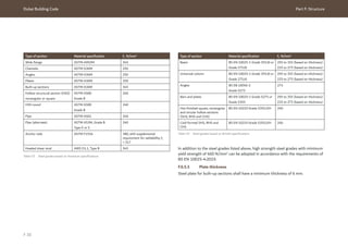
![Dubai Building Code Part F: Structure
F 31
F.6.5.4 Structural connections
F.6.5.4.1 Bolted connections
Bolted connections shall be designed and constructed
in accordance with AISC manual of steel construction
[Ref. F.15] including AISC specification for structural
joints using ASTM A325 or A490 bolts [Ref. F.16].
For higher strength applications (> 60,000 psi),
ASTM A307 shall be followed.
F.6.5.4.2 Welded connections
Welding design and procedures shall be in accordance
with AWS D1.1 or BS EN ISO 15614.
Welding should not be undertaken on-site. If
unavoidable, the detailed method of work with the
necessary certificates and tests shall be submitted
for approval. In addition, welding procedures shall be
implemented by accredited welders in accordance with
relevant AWS requirements.
Connections shall not be detailed to rely on the
combined strength of welding and bolting at the same
time under any circumstances.
F.6.5.4.3 Post-installed anchors
Post-installed anchors into reinforced concrete
elements may be used for the purpose of supporting
steelwork where it is impractical to install cast-in
anchors.
Post-installed anchors shall be designed based on the
provisions of ACI 318-19, with consideration for all
conceivable failure mechanisms (see Figure F.14). Figure F.14 Failure modes for anchors (© ACI. Modified figure based on Figure R17.5.1.2, ACI 318-19, pg. 238)
Key
01: Steel failure
02: Pullout
03: Concrete breakout
04: Concrete splitting
05: Side-face blowout
06: Bond failure – Single
07: Bond failure – Group
08: Steel failure preceded by concrete spall
09: Concrete pryout for anchors far from a free edge
10: Concrete breakout
01 02 03
08
09 10
04 05 06 07
N
N
N
N N
N N N
V
V
N
N
N
N
V
V
V
V
V
V
V
(a) Tensile loading
(b) Shear loading](https://image.slidesharecdn.com/dubaibuildingcodeenglish2021editionak-231227052107-72adb61a/85/Dubai-Building-Code_English_2021-Edition_AK-pdf-357-320.jpg)
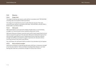
![Dubai Building Code Part F: Structure
F 36
NOTE: For further guidance, the mean monthly
temperatures and relative humidity values for specific
sites are available from the National Centre for
Meteorology and Seismology website
(www.ncms.ae/) [Ref. F.4]. Figure F.15 and Figure F.16
show air temperature data and relative humidity data,
respectively, from the National Centre for Meteorology
and Seismology.
Figure F.15 Air temperature data from National Centre for Meteorology
and Seismology
Figure F.16 Relative humidity data from National Centre for
Meteorology and Seismology
0
10
20
Temperature
(˚C)
30
40
50
Jan
Feb
Mar
Apr
May
Jun
Jul
Aug
Sep
Oct
Nov
Dec
Key
Maximum temperature
Mean maximum temperature
Mean temperature
Mean minimum temperature
Minimum temperature
0
10
20
Temperature
(˚C)
30
40
50
Jan
Feb
Mar
Apr
May
Jun
Jul
Aug
Sep
Oct
Nov
Dec
90
0
10
20
30
40
50
60
70
80
Humidity
(%)
Jan
Feb
Mar
Apr
May
Jun
Jul
Aug
Sep
Oct
Nov
Dec
Key
Mean maximum relative humidity
Mean relative humidity
Mean minimum relative humidity
90
0
10
20
30
40
50
60
70
80
Humidity
(%)
Jan
Feb
Mar
Apr
May
Jun
Jul
Aug
Sep
Oct
Nov
Dec](https://image.slidesharecdn.com/dubaibuildingcodeenglish2021editionak-231227052107-72adb61a/85/Dubai-Building-Code_English_2021-Edition_AK-pdf-362-320.jpg)
![Dubai Building Code Part F: Structure
F 37
F.7.12 Design for wind loading effects
F.7.12.1 Design basis
The Engineer shall calculate the effects of wind loading on buildings. The calculation
shall take into account strength for life safety, and serviceability for buildings
movements affecting cladding or building occupant comfort. Calculations for wind
design shall be based on ASCE/SEI 7-16. The Engineer shall also use supporting
information and additional rules for application in Dubai from the DBC.
NOTE: The rules are intended to fully cover buildings of the kind envisaged in the
writing of a code of practice. For unusual constructions, additional studies are
expected, such as wind tunnel testing, and might result in a need for an appropriate
variation of the rules.
F.7.12.2 Wind pressures
This clause provides the basis for calculation of wind pressures to be used with
ASCE/SEI 7-16. The wind speeds of Table F.10 shall be used instead of the wind
maps in Section 26.5 of ASCE/SEI 7 16.
The 50 MRI wind speed stated in Table F.10 shall only be used in accordance with
Clause 5.3.5 of ACI 318-19.
Table F.10 Reference wind speeds per risk category as defined in Clause 1.5 of ASCE/SEI 7-16 and mean
recurrence interval (MRI) as defined in the RWDI report [Ref. F.5]
ASCE/SEI
7-16 MRI
(years)
Reference wind speed
for 3 s gust at
10 m height on open
terrain, V = Vref (m/s)
Application
1 22 Serviceability – occupancy comfort (refer to F.7.12.4.2)
10 30 Serviceability – displacement (refer to F.7.12.4.1)
50 38 Strength in accordance with Clause 5.3.5 of ACI 318 19
300 44 Strength – category I
700 47 Strength – category II
1,700 51 Strength – category III
3,000 53 Strength – category IV
Where wind tunnel testing is used together with up-crossing or storm-passage
methods to account for directionality, the wind directionality factor (Kd) shall be
taken as 1.0.
In all cases, the design wind pressure shall be not less than 1 kN/m2
.](https://image.slidesharecdn.com/dubaibuildingcodeenglish2021editionak-231227052107-72adb61a/85/Dubai-Building-Code_English_2021-Edition_AK-pdf-363-320.jpg)
![Dubai Building Code Part F: Structure
F 39
F.7.12.4.2 Motions affecting occupant comfort
Accelerations of the uppermost occupied floor shall be assessed for return periods of
1 year and 10 year return with the structural damping described in F.7.12.5.
The motions shall be compared with internationally recognized criteria such as those
of ISO 10137 (see Figure F.17) or as described in ASCE guide wind-induced motion
of tall buildings: designing for habitability [Ref. F.6].
Motions of a building due to the wind might affect occupants directly or cause
motion of contents such as hanging objects and water, which can also cause concern
to some individuals. Motions should be kept within an appropriate limit, noting
that acceptability of motions is subjective and that other factors, including noises
resulting from building movement, can also trigger concerns.
F.7.12.5 Structural damping for assessment of wind responses
Unless design measures or special construction provide additional damping, the
estimates of structural damping of Table F.12 shall be used to assess motions under
serviceability conditions and for strength design. Values are given for buildings
with main lateral load resisting structure of steel or concrete. For composite steel/
concrete constructions, intermediate values should be used.
50
30
20
14
10
8
6
4
2
0.06 0.1 0.2 0.3 0.5 1 2 3 5
Acceleration
(milli-g)
Natural frequency (Hz)
Office
Residential
Figure F.17 Horizontal motion limits from ISO 10137 (Modified figure based on ISO 10137:2007, Bases
for design of structures - Serviceability of buildings and walkways against vibration. Reproduced with the
permission of the International Organization for Standardization, ISO.
Table F.12 Percentage of critical damping for normal buildings
Design condition Percent of critical damping
Concrete structures Steel structures
Serviceability 1% to 2% 0.75% to 1%
Strength design 1.5% to 2.5% 1% to 1.5%](https://image.slidesharecdn.com/dubaibuildingcodeenglish2021editionak-231227052107-72adb61a/85/Dubai-Building-Code_English_2021-Edition_AK-pdf-365-320.jpg)
![Dubai Building Code Part F: Structure
F 40
The final damping values chosen shall be based on studies carried out by the
Engineer and wind specialist.
Where additional damping is provided by moving mass dampers, strength shall be
verified taking account of the risk of non-operation. The motions of the damper at
beyond service design limits shall be limited in order to maintain safety in extreme
events.
F.7.13 Design for earthquake effects
F.7.13.1 Scope
Every structure, and portion thereof (including non-structural components that are
permanently attached to structures, and their supports and attachments) shall resist
the effects of earthquake motion in accordance with ASCE/SEI 7-16.
Where any building is modified and there is change to the stiffness or mass of
more than 10%, the seismic behaviour shall be reconfirmed and ASCE/SEI 7-16
requirements shall not be followed (refer to F.7.13.13).
F.7.13.2 Seismic performance criteria
Following the requirements of ASCE/SEI 7-16 would meet the life safety structural
performance level for a probabilistic ground motion, with a 2% probability of
exceedance within a 50-year period. The enhanced ground motion parameters given
in Table F.13 shall be used for design of building structures (refer also to F.10).
Where the Owner requires a specific level of seismic performance (such as the
immediate occupancy structural performance objective), the structural and non-
structural components shall be explicitly analysed and evaluated in line with the
requirements of Section 1.3.1.3 of ASCE/SEI 7-16. Both the proposed target
performance level and ground motion parameters shall be accepted by the Authority.
The performance of the building is dependent on the adequate performance of
both the structure and the non-structural components (e.g. MEP system, façade
and vertical transportation systems, etc.). All the structure and the non-structural
components shall be included in the seismic design process, in line with the
requirements of ASCE/SEI 7-16.
F.7.13.3 Seismic ground motion values
F.7.13.3.1 Near-fault sites
There are no known active faults mapped within 15 km of Dubai, so near-fault effects
do not need to be assessed. It is assumed that the West Coast Fault is not an active
seismotectonic structure [Ref. F.7].
F.7.13.3.2 Dubai acceleration parameters
In line with F.7.13.2, the seismic design criteria shall be modified as given in Table
F.13. These are hazard values and shall be used in ASCE/SEI 7-16 directly. No
corrections to adjust for risk-targeted ground motion shall be carried out.
Table F.13 Enhanced performance seismic ground motion parameters for Dubai (site class B)
Location SS S1 TL (s)
Dubai 0.51 0.18 24](https://image.slidesharecdn.com/dubaibuildingcodeenglish2021editionak-231227052107-72adb61a/85/Dubai-Building-Code_English_2021-Edition_AK-pdf-366-320.jpg)
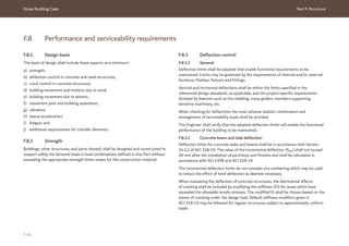
![Dubai Building Code Part F: Structure
F 45
F.8.3.3 Steelwork deflection limits
Deflection limits for steel structures shall conform to the requirements stipulated in
the AISC 360 and AISC design guide 3 [Ref. F.17].
The following points should also be taken into account.
a) For cantilever elements the span length can be equal to double the cantilever
length.
b) The deflection limits do not take into account pre-cambering, which may be used
to reduce the effect total deflection as deemed necessary.
F.8.3.4 Post-tensioned concrete deflection control
Design for strength and serviceability requirements of members shall conform to
ACI 318-19.
Structural calculations shall verify that short- and long-term deflections, camber,
vibration frequency and amplitude are within permissible limits.
Effects of cracking should be included by modifying the stiffness EI properties
as detailed in ACI 318-19.
Most PT concrete structures combine non-prestressed reinforced concrete,
un-cracked PT and cracked PT sections. The design method shall capture the real
behaviour of the structural system by taking into consideration the stiffnesses of the
cracked and un-cracked sections.
F.8.4 Crack control in concrete structure
The significance of cracking is contained within three categories.
a) Cracks that lead to durability problems and consequently a reduction in
structural capacity.
b) Cracks that lead to a loss of serviceability of the structure
(e.g. the leakage of water or damage to finishes).
c) Cracks that are aesthetically unacceptable.
Crack widths shall be controlled in accordance with maximum crack widths defined
in the referenced codes and standards. The Engineer shall perform crack width
calculation checks in accordance with ACI 224R.
It is also recommended that basements and liquid retaining structures be classified in
relation to the degree of protection against leakage. An appropriate limit to cracking
depending on the classification should be selected by the Engineer and Owner’s
representative, paying due regard to the required function of the structure, the
intrinsic durability requirements, and soil and water properties.
CIRIA C766 [Ref. F.10] provides guidance on aesthetically acceptable crack widths.
In the absence of more specific requirements, the following maximum crack width
limits shall be adopted.
1) For sections of the structure in contact with groundwater, the crack width
limits (wk) are defined as a function of the ratio of the hydrostatic pressure, hD
to the wall thickness of the containing structure, hw.
i) For hD/hw <5, wk = 0.2 mm.
ii) For hD/hw >35, wk = 0.05 mm.
2) For intermediate values of hD/hw, linear interpolation between 0.2 mm and
0.05 mm shall be used.
3) Section of the structure not in contact with water, wk = 0.3 mm.
4) Structural elements (such as piles) under permanent tension loads,
wk = 0.1 mm.
The above listed limits may be adopted providing that they do not contradict the
requirements of ACI 224R and that a proprietary waterproofing system is provided
for structural elements in contact with water in accordance with BS 8102.](https://image.slidesharecdn.com/dubaibuildingcodeenglish2021editionak-231227052107-72adb61a/85/Dubai-Building-Code_English_2021-Edition_AK-pdf-371-320.jpg)
![Dubai Building Code Part F: Structure
F 46
F.8.5 Crack control in restrained members
Where structural walls, columns and piles provide significant restraint to shrinkage
and temperature movements, the reinforcement provisions should be verified against
the requirements stated under either ACI 89-S15 (as in R24.4.2 of ACI 318-19)
or CIRIA C766 [Ref. F.10].
F.8.6 Drift and deformation of buildings
F.8.6.1 General
The Engineer shall assess the drift and deformation of the building considering
the whole life of the structure, including the construction stages.
F.8.6.2 Drift due to permanent gravity load
The Engineer and Contractor shall verify that any deviation from plumbs for the
building and cores, under permanent gravity loads only, conforms to the limits stated
in Section 7 of ACI 117-10.
If necessary, the Engineer shall specify any correction in the setting out of the
building. This should be validated by the Contractor, taking into account the sequence
and method of construction.
F.8.6.3 Drift and deformation due to differential vertical shortening
A non-linear static construction sequence analysis should be performed to assess
deflection and drift due to differential vertical shortening. At a minimum, the analysis
shall be performed by the Engineer and/or Contractor for the following structures:
a) multi-storey buildings with different stresses between the core and perimeter
columns;
b) structures with an asymmetrical structural plan layout and/or asymmetrical
massing;
c) buildings with stepped setbacks;
d) buildings with outriggers.
The Engineer shall assess the impact of the following design aspects:
1) elastic shortening;
2) creep and shrinkage of concrete structures where the Engineer shall refer to
ACI 209.2R and the environmental conditions of Dubai as discussed in F.7.11;
3) foundation settlements;
4) transfer elements, as discussed in F.8.10; and
5) construction stages.
The analysis methodology and parameters adopted shall be discussed and agreed
with the Authority. The Contractor shall review and validate the differential vertical
shortening analysis as it is strongly dependent on the construction stages sequence.
The Contractor shall submit the type of corrections to be implemented on-site to the
Engineer and Authority, for review and approval.
F.8.6.4 Drift and deformation due to wind
Drift and deformation due to wind shall be assessed in accordance with F.7.12.4.
F.8.6.5 Drift and deformation due to seismic
Movements of buildings due to earthquake effects shall conform to the requirements
stipulated under Section 12.12 of ASCE/SEI 7-16.](https://image.slidesharecdn.com/dubaibuildingcodeenglish2021editionak-231227052107-72adb61a/85/Dubai-Building-Code_English_2021-Edition_AK-pdf-372-320.jpg)
![Dubai Building Code Part F: Structure
F 47
F.8.7 Movement joints and building separation
Movement joints shall be provided, where necessary, to address the requirements of
expansion and/or deflection under load for above-ground structures. The minimum
separations between a structure and any surrounding obstructions shall not be less
than the total maximum displacement (δMT)as specified in Section 12.12 of
ASCE/SEI 7-16:
F.8.8 Vibration
F.8.8.1 Steelwork
The natural frequency of steelwork floor systems for normal occupancy shall be
evaluated in accordance with AISC design guide 11 [Ref. F.18] or
SCI P354 [Ref. F.19].
F.8.8.2 Concrete
Cast-in-place floor systems designed in accordance with the minimum thickness
and deflection requirements of ACI 318-19, have generally been found to provide
vibration performance suitable for human comfort under typical service conditions.
However, there might be situations where serviceability conditions are not satisfied.
For example:
a) long spans and open floor plans;
b) floors with strict vibration performance requirements such as precision
manufacturing and laboratory spaces; and
c) facilities subject to rhythmic loadings or vibrating mechanical equipment.
Further guidance can be sought in the ATC Design Guide 1 [Ref. F.13].
The performance of PT concrete floors may follow the recommendation of
TR43, Table 1 [Ref. F.11]. For those PT concrete floors that do not follow these
recommendations, their performance should be assessed in accordance with the
dynamic assessment method defined in TR43, Appendix G [Ref. F.11].
Precast concrete structures shall be checked for vibration as detailed in Section 9.7 of
PCI design handbook [Ref. F.12].
δMT=√((δM1 )2
+(δM2 )2
) Eq. F.7
Where δM1 and δM2 are the maximum inelastic response displacements of the
adjacent structures at their adjacent edges.
δM=(Cd δmax)/Ie Eq. F.8
Where:
Cd is the deflection amplification factor in Table 12.2-1 of ASCE/SEI 7-16;
δmax is the maximum deflection at the location required by this section, determined by
an elastic analysis; and
Ie is the importance factor determined in accordance with 11.5.1 of ASCE/SEI 7-16.
Movement joints are a common source of water infiltration. Structures should be
designed below ground level, without movement joints to mitigate the risk of water
ingress. Design for construction without permanent joints below ground level can be
achieved by following the recommendations provided in the CIRIA C766 [Ref. F.10].](https://image.slidesharecdn.com/dubaibuildingcodeenglish2021editionak-231227052107-72adb61a/85/Dubai-Building-Code_English_2021-Edition_AK-pdf-373-320.jpg)
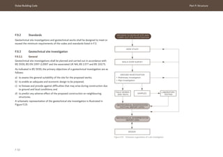
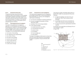
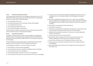
![Dubai Building Code Part F: Structure
F 53
Figure F.21 Typical geological section
Key
01-07: Boreholes
08: Ground fill
09: Sand
10: Sandstone
11: Conglomerate
12: Calcisiltite
The GIR shall include the following details as a minimum when submitted to the
Authority:
1) details of the recommended foundation system, with allowable bearing capacity,
modulus of sub-grade reaction and allowable settlement;
2) provision to mitigate the effects of expansive and collapsible soils in accordance
with the recommendations provided in Ch. 32 and 33 of the ICE Manual of
geotechnical engineering (vol. I) [Ref. F.20];
3) provision to mitigate the effect of soil liquefaction, which shall be assessed as
stipulated in F.9.4.5;
4) provision to mitigate the effect of soil settlement and loads from adjacent plots;
5) various seismic parameters for the uppermost 30 m, in accordance with the
specified codes;
6) piles working load capacity under compression and tension for different sizes, at
varying depths and effective length (all levels should be in DMD);
7) if applicable, recommendations for pile groups with modification factors for load
and settlement;
8) values of modulus of elasticity of soil (Es);
9) horizontal modulus of sub-grade reactions (Kh);
10) constant of horizontal sub-grade reaction (nh);
11) vertical spring constants (Kv);
12) Poisson’s ratio;
13) piles stiffness (Ks);
14) optimal spacing between piles within a pile group;
01 02 03 04 05 06 07
08 09 10 11 12](https://image.slidesharecdn.com/dubaibuildingcodeenglish2021editionak-231227052107-72adb61a/85/Dubai-Building-Code_English_2021-Edition_AK-pdf-379-320.jpg)
![Dubai Building Code Part F: Structure
F 54
15) soil parameters required for shoring and basement wall design, such as:
i) average bulk density;
ii) angle of shearing resistance;
iii) cohesion;
iv) coefficients of soil pressure at rest (K0) pressure; and
v) coefficient of active and passive soil pressure for all soil layers.
16) soil classification and index test results (particle size distribution, plasticity
chart);
17) rock classification and index test results;
18) permeability of soil and rock layers;
19) plan showing boreholes, in-situ test location and coordinates;
20) water table level (in DMD) and temperature;
21) laboratory test results on soil and groundwater samples for the presence
and concentration of pH, sulphate and chloride, or any other chemicals or
components that might affect the structure;
22) type of cement based on the chemical test results of soil types;
23) summary of soil parameters;
24) subsoil conditions and description;
25) recommendation on the earth work, excavation, filling and compaction; and
26) recommendations for suitability of site material to be used as fill material.
F.9.4 Geotechnical design
F.9.4.1 Earthworks (excavation and filling)
Excavation works shall be designed in accordance with BS EN 1997-1:2004 and the
associated UK NA and BS 6031. The design recommendations of Ch.23 of the ICE
manual of geotechnical engineering (vol. I) [Ref. F.20] should also be followed for the
slope stability analysis.
The Geotechnical Specialist Contractor shall provide slope stability analysis for any
open cut excavation (see Figure F.22).
Figure F.22 Open cut excavation](https://image.slidesharecdn.com/dubaibuildingcodeenglish2021editionak-231227052107-72adb61a/85/Dubai-Building-Code_English_2021-Edition_AK-pdf-380-320.jpg)
![Dubai Building Code Part F: Structure
F 55
The Geotechnical Specialist Contractor shall design remedial actions when slopes
display signs of instability or the geotechnical analysis confirms the risk of failing.
The list below presents some of the common slope stabilization techniques which
may be used in Dubai.
a) Regrading of the slope. If the available land plot permits, the slope can be
regraded to reduce the slope angle.
b) Drainage. Deep drains are perforated plastic tubes that can be embedded into the
slope to reduce the pore water pressure.
c) Retaining wall. Retaining walls shall be designed in accordance with F.9.4.3.
d) Soil nailing. An in-situ reinforcement technique consisting of drilling or driving
steel bars into the soil mass (see Figure F.23 and Figure F.24). The soil nails are
secured to steel plates at the surface and optional erosion and vegetation control
geosynthetic mesh can be placed over the slope face. If the soil is loose on the
surface, concrete can be sprayed to cover the slope face (see Figure F.23). Further
guidance can be sought in Ch. 74 of the ICE manual of geotechnical engineering
(vol. II) [Ref. F.20].
e) Filling material. The material used for backfilling purposes shall be of selected fill
composed of a sand/granular mixture. The plasticity index of the backfill material
should not exceed 10%. The maximum particle size of backfill material shall not
exceed 75 mm. The percentage passing through a 75 mm sieve shall not exceed
20%. The organic materials content shall not exceed 2% and the water-soluble
salt content shall not exceed 5%
f) Compaction. The backfill materials shall be placed in layers of thickness 150 mm
to 250 mm and compacted to not less than 95% of the maximum dry density.
The Engineer shall state whether the material available on site could be used for
general backfilling or not after performing the necessary analysis.
Figure F.23 Soil nailing detail (Modified figure based on Figure 2.1 from CIR 7 FHWAO-IF-03-017, Geotechnical
Engineering Circular No.7, Soil Nail Walls, 2003, United States Department of Transportation Federal Highways
Administration)
Key
01: Permanent facing (e.g.
cast-in-place reinforced
concrete)
02: Temporary facing
(shotcrete)
03: Geocomposite strip drain
04: Grout
05: Steel bar
06: Welded wire mesh
07: Reinforcement
08: Bearing plate
09: Washers
10: Nail head
11: Studded head
11
10
09
08
03
06
07
05
01 02
04](https://image.slidesharecdn.com/dubaibuildingcodeenglish2021editionak-231227052107-72adb61a/85/Dubai-Building-Code_English_2021-Edition_AK-pdf-381-320.jpg)
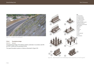
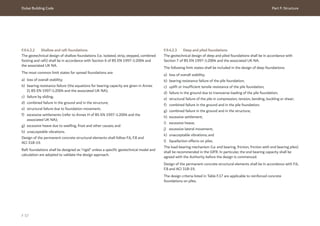
![Dubai Building Code Part F: Structure
F 58
Design criterion Minimum requirement
Pile design: general Ensure pile design allows for both gravity and lateral loads.
Piles to be designed for out of verticality tolerance of 1/75.
Piles to be designed for eccentricity of vertical load of 75 mm.
Factor of safety shall be at least 2.5, unless geotechnical model
and geotechnical calculations based on the geotechnical site
investigation are provided.
Minimum rock socket length of three times pile diameter.
The use of bentonite is not recommended. If it is used, the shaft
capacity shall be reduced.
Pile caps shall be designed in accordance with the requirements
specified under ACI 318-19 and the CRSI design
handbook [Ref. F.8].
Crack width limit for tension
piles (wk)
0.2 mm considering the tension load.
0.1 mm considering the uplift load due to permanent tension load
(i.e. groundwater uplift, out of balance gravity loads).
Geotechnical design parameters The recommendations provided in the GIR shall be followed unless
a specific geotechnical model and geotechnical calculation are
developed.
Materials test reports
(aggregate, steel, concrete, etc.)
To be implemented by laboratories approved by DM or EIAC.
Minimum bar diameter 12mm
Minimum number of bars Six bars evenly spaced.
Minimum percentage of
reinforcement
To be provided for the full length of the piles in order to provide
ductility and in accordance with Table 18.13.5.7.1 of ACI 318-19.
Minimum stirrup reinforcement Bars of 10 mm diameter for all the piles.
The top region of the pile below the caps or raft, shall be confined
effectively with closely spaced stirrups, for a length of three times
the pile diameter.
Stirrup reinforcement shall be in accordance with Table 18.13.5.7.1
of ACI 318-19.
Design criterion Minimum requirement
Minimum design of horizontal/
lateral force
For the lateral pile design, the following requirements shall be
included:
a) minimum 5% of pile capacity and not less than the horizontal
loads resulting from the superstructure and foundation
analysis;
b) moments due to out of position (75 mm) piles; and
c) horizontal force due to verticality (1/75).
The above design (a) may be excluded if geotechnical calculations
and geotechnical models are provided and the following items are
included in the design:
1) isolated temperature changes within raft, and temperature
distribution from column to raft;
2) detailed pile group assessment considering soil-structure
interaction, building stiffness and foundation stiffness;
3) moments due to slab dishing;
4) kinematic effects of earthquake loading;
5) sensitivity checks should piles be constructed out of position;
6) embedment of raft; and
7) lateral load path analysis and load transfer into the raft slab.
Rational study of pile spacing
not available
Minimum pile spacing shall be 2.5 times the diameter.
Pile stress under compression
load
Maximum 25% of concrete strength.
Lateral stiffness of piles 50% to 100% of vertical stiffness.
Any other percentage (such as 10% to 15% of vertical stiffness)
shall be justified by geotechnical models and calculations including
the piles lateral group effect.
Vertical stiffness of piles The impact of subsidence of the piles group on vertical stiffness,
as well as its effect on the raft and piles, shall be validated by
geotechnical models and calculations.
Table F.17 Piles foundation minimum design criteria](https://image.slidesharecdn.com/dubaibuildingcodeenglish2021editionak-231227052107-72adb61a/85/Dubai-Building-Code_English_2021-Edition_AK-pdf-384-320.jpg)
![Dubai Building Code Part F: Structure
F 59
F.9.4.3 Shoring and earth retaining system
F.9.4.3.1 General
The geotechnical design of earth retaining systems shall be performed in accordance
with Section 9 of BS EN 1997-1:2004+A1:2013 and the associated UK NA. Design
of the concrete structural elements shall follow F.6, F.8 and ACI 318-19.
Shoring systems and retaining structures are deemed to be temporary if the design
life of the system is less than two years. They shall not be deemed to be part of
the permanent structures and a physical segregation shall be provided between
temporary and permanent structural systems.
The shoring and retaining systems shall be designed to retain the soil and actual
groundwater pressure (including tidal effect).
NOTE: Shoring and earth retaining systems typically used and accepted in Dubai are
as follows:
a) non-watertight shoring systems:
1) soldier piles with lagging system/king post walls;
2) contiguous pile walls;
3) slurry walls;
b) watertight shoring systems:
1) secant pile walls;
2) diaphragm walls;
3) sheet piles;
c) bracing for temporary earth retaining systems:
1) anchors;
2) rakers; and
3) struts.
Alternative techniques specified in accordance with international codes and
standards may also be accepted.
The shoring and bracing systems are further described in Ch. 62, 63 and 64 of the
ICE manual of geotechnical engineering (vol. II) [Ref. F.20].](https://image.slidesharecdn.com/dubaibuildingcodeenglish2021editionak-231227052107-72adb61a/85/Dubai-Building-Code_English_2021-Edition_AK-pdf-385-320.jpg)
![Dubai Building Code Part F: Structure
F 60
F.9.4.3.2 Required shoring systems
Table F.18 should be followed for different depths of excavation and site conditions.
Type of shoring system Permitted under following criteria
All types up to 5 m deep excavation;
one basement.
All types, except soldier pile
with lagging
up to 9 m depth and no buildings in the adjacent plots.
Shoring system preventing
water leakage
presence of buildings in the adjacent plots;
high groundwater level;
proximity to water bodies.
Table F.18 Type of shoring system
It is possible to adopt shoring systems other than those in Table F.17, based on
the soil examination report, groundwater level, presence of water sources, adjacent
buildings and surrounding constructions.
The minimum requirements listed in Table F.19 shall be included in the design of
temporary shoring systems.
Design criteria Minimum requirement
Minimum additional loads Additional uniform distributed load of 20 kN/m2
shall be taken into
consideration in proximity to roads and land plots. The additional
surcharge load needs to be assessed based on the actual conditions
on-site and adjacent structures.
Minimum distance between
anchors
1.2 m
Maximum length of anchors 10 m
Minimum length of anchors 3 m
Maximum lateral displacement 40 mm
Unplanned excavations Retaining walls shall be designed assuming presence of unplanned
excavations in front of the wall, with depth of not less than 10%
of the total height of vertical walls, or 10% of vertical distance
between the lowest anchor and the bottom of the excavation, but
not less than 0.5 m.
Heave The geotechnical design shall assess heave if swelling and
collapsible soils have been identified in the GIFR. Further guidance
can be sought in Ch. 32 and 33 of the ICE Manual of geotechnical
engineering (vol. I) [Ref. F.20].
Table F.19 Minimum requirements for earth retaining system](https://image.slidesharecdn.com/dubaibuildingcodeenglish2021editionak-231227052107-72adb61a/85/Dubai-Building-Code_English_2021-Edition_AK-pdf-386-320.jpg)
![Dubai Building Code Part F: Structure
F 61
F.9.4.3.3 Permanent earth retaining system
Any retaining structure is deemed to be permanent if the design life of the system is
more than two years. The permanent retaining system shall be designed to retain the
soil and future groundwater pressure (including tidal effect) without allowing for the
temporary retaining system.
The temporary retaining structures listed under the NOTE to F.9.4.3.1 may be
designed as permanent structures, provided they are included in the analysis of the
overall structure. The same design life, performance and durability requirements shall
be applied to both the main structural system and the permanent retaining system.
In addition to the requirements for temporary retaining systems stipulated under
F.9.4.3.2, the Engineer shall design the retaining system with consideration for
the intended design life. In particular, the Engineer shall consider the applicable
performance, serviceability and durability requirements stated in F.5.6 and F.8.
The geotechnical design of permanent earth retaining systems (including
counterfort/buttressed wall systems) shall be performed in accordance with
Section 9 of BS EN 1997-1:2004 and the associated UK NA. Design of the concrete
structural elements shall be in accordance with F.6, F.8 and ACI 318-19.
F.9.4.3.4 Basement walls
A permanent basement concrete wall should be provided in front of the temporary
retaining systems detailed in F.9.4.3.2. The permanent basement wall shall be
designed to retain the soil and future groundwater pressure (including tidal effect)
without considering the temporary retaining system.
The permanent basement wall shall be fully integrated with the main structural
system of the building. The same design life, performance and durability
requirements shall be applied to the main structural system and the basement walls.
The geotechnical design of permanent basement walls shall be performed in
accordance with Section 9 of BS EN 1997-1:2004 and the associated UK NA. Design
of the concrete structural elements shall follow F.6, F.8 and ACI 318-19.
F.9.4.4 Groundwater control and dewatering
Dewatering systems shall be designed in accordance with BS EN 1997-1:2004, and
the associated UK NA and CIRIA C750 [Ref. F.21], taking into account the following.
a) All existing facilities shall always be protected.
b) The dewatering system shall reduce the loss of soft materials in the soil and any
effect on the surrounding structures. The hydrogeological model shall identify and
assess any piping effect (see Figure F.26).
c) The depth of shoring systems and internal excavations shall prevent soil heave.
This is to avoid the possibility of seepage, and to ensure compatibility between
the designs of the shoring systems and the dewatering system (see Figure F.27).
d) A seepage analysis and groundwater/hydrogeological model shall be prepared for
at least 20 m below the bottom of the excavation. The model shall determine the
following:
1) type of soil and rocks;
2) horizontal permeability of each layer;
3) incoherent or gypsum soils; and
4) other areas exposed to water leakage under the surface.
Figure F.28 shows the permeability of different soil types and recommended
dewatering systems.](https://image.slidesharecdn.com/dubaibuildingcodeenglish2021editionak-231227052107-72adb61a/85/Dubai-Building-Code_English_2021-Edition_AK-pdf-387-320.jpg)
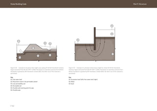
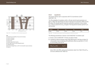
![Dubai Building Code Part F: Structure
F 64
Site class Short period FPGA
A 0.80
B 0.90
C 1.27
D 1.54
E 2.25
F See F.7.13.9
Table F.21 PGA site coefficient FPGA for liquefaction assessment in Dubai
The factor of safety (FS) against the occurrence of earthquake-induced liquefaction
shall be defined as the available soil resistance to liquefaction, the cyclic resistance
ratio (CRR) divided by the cyclic stress generated by the design event, the cyclic
stress ratio (CSR) as shown in Eq. F.10. The FS shall not be less than 1.5.
The requirements for foundations design in liquefiable sites shall follow the
requirements in Section 12.13.9 of ASCE/SEI 7-16 and associated subclauses. This
shall include consideration of the following issues regarding liquefaction, namely:
a) lateral spreading;
b) global and differential settlements;
c) provision of ties between individual foundations; and
d) negative skin friction (i.e. downdrag) on vertical capacity of piles.
Where the impact of liquefaction exceeds the requirements of ASCE/SEI 7-16
(Table 12.13-2 for lateral spreading and Table 12.13-3 for differential settlement
thresholds), then suitable ground improvement shall be required.
F.9.4.6 Ground improvement
Ground improvement shall be designed according to BS EN 1997-1 and the ICE
Manual of geotechnical engineering (vol. I) Ch.25 [Ref. F.20].
NOTE: The following ground improvement techniques are accepted in Dubai
(see Figure F.29):
a) dynamic compaction;
b) vibro-compaction;
c) soil replacement;
d) soil mixing;
e) grouting; and
f) vertical drains.
Alternative techniques specified in accordance with international codes and
standards may also be accepted.
FS≥1.5(CRR/CSR) Eq. F.10
The groundwater level shall be selected based on the peak over the design period,
which allows natural changes (such as the “spring” tide peak), land use changes and
considerations for global warming.
In calculating the CSR, a magnitude of 6.2 shall be used for Dubai.
When assessing the potential for liquefaction any published and internationally
accepted methodology can be used provided it is internally consistent. It is
recommended to use the “Idriss Boulanger Method” [Ref. F.9]. The impact of
carbonate sands on the liquefaction potential should also be included.](https://image.slidesharecdn.com/dubaibuildingcodeenglish2021editionak-231227052107-72adb61a/85/Dubai-Building-Code_English_2021-Edition_AK-pdf-390-320.jpg)
![Dubai Building Code Part F: Structure
F 66
F.9.5 Execution of geotechnical works
F.9.5.1 General
Geotechnical works shall be carried out in accordance with the BS EN standards
listed in F.3.1.5. The Engineer and Geotechnical Specialist Contractor shall also
conform to the following clauses.
F.9.5.2 Earthworks (excavation and filling)
In addition to the requirements of BS EN 6031, the following requirements shall be
included in the execution of excavation and backfill activities.
a) The materials used for backfilling purposes shall consist of selected materials
such as sand/granular mixture free from organic materials or other biodegradable
materials. The Engineer shall determine whether excavated materials can be used
in general backfilling works after conducting the necessary testing.
b) All excavations exceeding 1.2 m in depth require an excavation permit issued by
the Authority.
c) All health and safety requirements shall be strictly followed while executing any
excavation works.
d) All excavation activities shall be carried out inside the plot limits only.
A no encroachment, no parking, and no stopping zone with a minimum width
of 1 m shall be provided in proximity to the excavated area.
e) For any works required outside of the plot limits, no objection certificate (NOC)
/approval from all the relevant Authorities, departments or plot Owners shall be
submitted.
f) Execution of excavation and filling activities shall conform to the requirements
stipulated in Ch.75 of the ICE manual of geotechnical engineering
(vol. II) [Ref. F.20].
g) Installation of soil nails shall conform to the requirements of BS EN 14490.
Further guidance can be sought in Ch. 88 of the ICE manual of geotechnical
engineering (vol. II) [Ref. F.20].
F.9.5.3 Shoring retaining systems
In addition to the requirements of BS 8081, BS EN 1536, BS EN 1537, BS EN 1538
and BS EN 12063, the following requirements shall be included in the construction of
earth retaining structures.
a) All existing structures and utilities shall always be protected.
b) All works of shoring systems shall be carried out within the land plot. The
Geotechnical Specialist Contractor shall obtain all required approvals from all
concerned Authorities and Owners of the adjacent plots regarding any shoring
system or anchors protruding outside the land plot limits.
c) The top 2 m of the shoring systems on the roads or services side shall be removed
upon completion of the basement wall works.
d) All works of shoring systems shall be continuously monitored by the Geotechnical
Specialist Contractor.
e) Anchors can be removed on-site only after obtaining the written consent
of the Engineer.
F.9.5.4 Foundations
It is envisaged that the following foundation systems will be typically provided
for buildings in Dubai:
a) shallow foundations;
b) deep foundations; and
c) raft foundations.
In addition to the requirements of BS EN 1536, BS EN 12699 and BS EN 14199,
the minimum testing criteria listed in Table F.22 shall be followed during and after
the execution of reinforced concrete foundations on piles.](https://image.slidesharecdn.com/dubaibuildingcodeenglish2021editionak-231227052107-72adb61a/85/Dubai-Building-Code_English_2021-Edition_AK-pdf-392-320.jpg)
![Dubai Building Code Part F: Structure
F 67
Test Minimum requirement
Static test on working piles Minimum 1% of all piles and each different
diameter
Dynamic test on working piles 5% of all piles
Cross-hole sonic logging (for more than 1 m
diameter and 20 m length)
10% of all piles 900 mm or greater with minimum
four tubes/holes and minimum three tubes for
750 mm. Minimum length of testing 20 m or full
length if shorter. End bearing piles full length
testing
Integrity test working piles 100%
Cubes test (concrete) as per technical specification
Reinforcement test as per technical specification
Table F.22 Minimum testing requirements for pile foundation
It is the responsibility of both the Engineer and the Geotechnical Specialist
Contractor to select a test location which does not interfere with the location of
the permanent structural piles of the main structure. The Geotechnical Specialist
Contractor may propose test locations to be reviewed by the Engineer who may
accept them or propose alternative locations. Non-working preliminary test pile
(PTP) location and arrangement shall be submitted officially to the Authority during
the design stage and shall at least include the following.
1) Detailed drawings that clearly show the location of the test pile and
instrumentation.
2) Information detailing the planned duration of the PTP.
3) An official covering letter from the Engineer and/or the Geotechnical Specialist
Contractor.
4) Minimum 1No. PTP for each project. The maximum diameter and length of pile
should be considered, assuming that they are the most suitable for the site.
PTP results shall be used to optimize the pile design in accordance with
BS EN 1997-1:2004 and the associated UK NA.
F.9.5.5 Groundwater control and dewatering
In addition to the requirements given in CIRIA C750 [Ref. F.21], the following
requirements shall also be included during the execution of dewatering on-site.
a) All existing facilities and utilities shall always be monitored and protected by the
Geotechnical Specialist Contractor.
b) A network shall be developed to monitor the groundwater pressure/piezometric
pressure separated from the dewatering system, the vertical groundwater
gradients as well as the horizontal gradients, and the water rises inside and
outside the excavations/the shoring systems.
c) Dewatering works shall not be stopped without the written approval of the
Engineer, after achieving balance between water pressure and the weight of
construction. The factor of safety shall be at least 1.1, irrespective of the friction
between walls and soil.
d) Care shall be taken during the dewatering process to ensure that fine particles soil
is not removed during pumping, as this may lead to unexpected subsidence in the
surrounding lands and the associated structures.](https://image.slidesharecdn.com/dubaibuildingcodeenglish2021editionak-231227052107-72adb61a/85/Dubai-Building-Code_English_2021-Edition_AK-pdf-393-320.jpg)
![Dubai Building Code Part F: Structure
F 69
F.10 Annex: Seismic acceleration and damping parameters
F.10.1 Seismic hazard in Dubai
A seismic hazard assessment for Dubai was commissioned by DM and carried out by
StrongMotions Inc. [Ref. F.22], for the purposes of supporting the seismic regulations
in this Part.
The acceleration parameters used are taken directly from Malhotra [Ref. F.22].
In this Annex the values are compared with other published studies for the region
(see Table F.23). There is consistency between several studies, but other studies
indicate higher seismicity in Dubai. Those studies have been reviewed by several
authors and are proposed to be inappropriate for the reasons highlighted in the table.
Reference Return periods Comment
475 years 975 years 2,475 years
Malhotra [Ref. F.22] 0.05 0.06 0.08 -
Irfan et al. [Ref. F.23] 0.06 - 0.12 Consistent with
Malhotra [Ref. F.22].
Shama [Ref. F.24] 0.17 - 0.33 Includes the West Coast Fault
as an active structure in their
model.
Aldama et al. [Ref. F.25] 0.05 0.06 0.09 Consistent with
Malhotra [Ref. F.22].
Pascucci et al. [Ref. F.26] 0.06 - 0.11 Consistent with
Malhotra [Ref. F.22].
Musson et al. [Ref. F.27] 0.05 - - Consistent with Malhotra
[Ref. F.22]. Only presents
results for one return period.
Sigbjornsson and
Elnashai [Ref. F.28]
0.16 0.18 0.22 Includes the West Coast Fault
as an active structure in their
model.
Abdalla and Al Homoud
[Ref. F.29]
0.14 - - Source zone model allows
seismicity from Iranian
coastline up to the UAE coast.
Grünthal et al. [Ref. F.30] 0.32 - - Regional study. The result
was not calculated but
extrapolated across the UAE.
Al-Haddad et al.
[Ref. F.31]
< 0.05 - - Consistent with
Malhotra [Ref. F.22], but only
a limited regional study.
Table F.23 Comparison of geometric mean PGA (g) calculated from various references (results to two decimal
places)](https://image.slidesharecdn.com/dubaibuildingcodeenglish2021editionak-231227052107-72adb61a/85/Dubai-Building-Code_English_2021-Edition_AK-pdf-395-320.jpg)
![Dubai Building Code Part F: Structure
F 70
F.10.2 Seismic parameters for ASCE/SEI 7-16
F.10.2.1 Component of ground motion
ASCE/SEI 7-16 defines the seismic parameters using the maximum rotated
component of ground motion rather than geometric mean component of ground
motion. To account for this variation the component of ground motion,
Malhotra [Ref. F.22] recommends the ratios in Table F.24. The proposed values are
consistent with similar published factors (e.g. Beyer and Bommer [Ref. F.32]).
Parameter Ratio
PGA 1.20
PGV 1.22
PGD 1.25
Table F.24 Resultant/geometric mean ratios (Malhotra, 2020)
ASCE/SEI 7-16 also adjusts the seismic hazard to ensure risk-consistent hazard
parameters for typical USA building stock following the procedure proposed by
Luco [Ref. F.33]. Malhotra [Ref. F.22] recommends that this adjustment is not
made, since the building stock in Dubai is considerably different to the USA and the
uncertainty in the methodology is large.
F.10.2.2 Return period
ASCE/SEI 7-16 defines the hazard in terms of a 2% probability of exceedance in 50
years, otherwise known as a return period of 2,475 years. As discussed in Malhotra
[Ref. F.22], a factor of two-thirds is applied to approximate the hazard in the USA to
approximate a return period of 475 years, as used in the previous degeneration of
seismic codes. This is an arbitrary requirement, which is country specific.
In contrast the Canadian building Code uses a 2,475-year return period directly.
The reason is because this lower probability is considered to provide a more uniform
margin of collapse, one that is much nearer to the probability of structural failure.
Similarly, the UK National Annex to BS EN 1998-1 also uses a 2,475-year return
period. This is to ensure seismic design is applied to the most critical structures in
what is generally a region of very low seismicity.
Since Dubai is principally affected by large distant events in Iran, it is considered
appropriate not to reduce the seismic hazard level using the arbitrary two-thirds
factor used in the USA, but ensure seismic design caters for these larger events.
This should not increase the seismic demand compared to current design practice.](https://image.slidesharecdn.com/dubaibuildingcodeenglish2021editionak-231227052107-72adb61a/85/Dubai-Building-Code_English_2021-Edition_AK-pdf-396-320.jpg)
![Dubai Building Code Part F: Structure
F 71
F.10.3 West Coast Fault
The West Coast Fault is presented as a structure on the tectonic map of the Arabian
Peninsula in Johnson (1998) [Ref. F.36]. The interpretation was based on figures
presented by Murris [Ref. F.34] and Hancock et al. [Ref. F.35]. Both references show
the West Coast Fault as a right lateral strike slip fault running along the coast from
Abu Dhabi through Dubai and Sharjah to Ras Al Khaimah, whereas
Johnson [Ref. F.36] shows this as a left lateral strike slip fault. They also both focus
on the Dibba line as the principal fault within the UAE and do not even discuss the
West Coast Fault.
The existence of the West Coast Fault is at best contentious. Some tectonic and
seismic hazard studies of the region do not include this fault as a local tectonic
feature (e.g. Pascucci et al., 2008, Aldama-Bustos et al. [Ref. F.25]). Other seismic
hazard studies include the West Coast Fault as a seismic source (e.g. Sigbjornsson
and Elnashai [Ref. F.28]); however details regarding the modelling parameters are
poorly defined.
A study was undertaken by Megahed et al. [Ref. F.37] on behalf of the Abu Dhabi
Department of Municipal Affairs to determine the threat posed to the UAE by the
West Coast Fault. The findings of this study rejected the existence of the West Coast
Fault. This agrees with the conclusions of the geological mapping of the area by the
British Geological Survey [Ref. F.27].](https://image.slidesharecdn.com/dubaibuildingcodeenglish2021editionak-231227052107-72adb61a/85/Dubai-Building-Code_English_2021-Edition_AK-pdf-397-320.jpg)
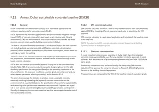
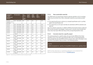
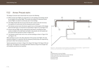
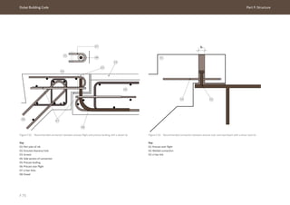
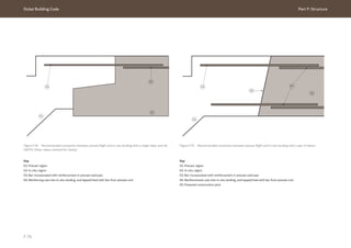
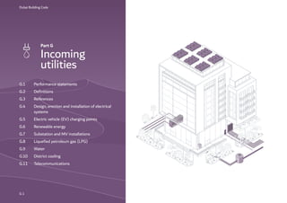
![Dubai Building Code Part G: Incoming utilities
G 4
Current-using equipment: Equipment which converts
electrical energy into another form of energy, such as
light, heat or motive power.
Demand factor: Ratio of maximum demand of the
system to the total connected load.
Design current: Magnitude of the current [root mean
square (RMS) value for AC] to be carried by the circuit
in normal service.
Direct current (DC): Unidirectional flow of an electric
charge.
Distribution board: Assembly containing switching
or protective devices (e.g. fuses, circuit breakers, and
residual current operated devices) associated with
one or more outgoing circuits, fed from one or more
incoming circuits, together with terminals for the
neutral and protective circuit conductors. It may also
include signalling and other control devices. Means
of isolation may be included in the board or may be
provided separately.
Diversity factor (or diversity): Ratio of sum of
individual maximum demands of the different type of
load during a specified period to the maximum demand
of the power station during the same period.
Duct: Enclosure of metal or insulating material, other
than conduit or cable trunking, intended for the
protection of cables which are drawn in after erection
of the ducting.
Earth: Conductive mass of the earth, of which the
electric potential at any point is conventionally taken
as zero.
Earth continuity conductor (ECC): Conductor used
for some measures of protection against electric
shock and intended for connecting together any of the
following parts:
a) exposed conductive parts;
b) extraneous-conductive parts;
c) the main earthing terminal;
d) earth electrode(s); or
e) the earthed point of the source, or an artificial
neutral.
Earth electrode: Conductor or group of conductors
in intimate contact with and providing an electrical
connection to earth.
Earth electrode resistance: Resistance of an earth
electrode to earth.
Earth fault current: Fault current which flows to earth.
Earth fault loop impedance: Impedance of the earth
fault current loop starting and ending at the point of
earth fault.
Earth leakage: Current which flows to earth, or to
extraneous-conductive parts, in a circuit which is
electrically sound.
Earth leakage circuit breaker (ELCB): Safety device
with high earth impedance which interrupts the circuit
if a dangerous voltage (50 V AC or over) is detected.
Earthing: Connection of the exposed conductive parts
of an installation to the main earthing terminal of that
installation.
Earthing conductor: Protective conductor connecting
the main earthing terminal of an installation to an
earth electrode or to other means of earthing.
Electric shock: Dangerous physiological effect resulting
from the passing of an electric current through a
human body or livestock.
Electrical installation: Assembly of associated electrical
equipment supplied from a common origin to fulfil
a specific purpose and having certain coordinated
characteristics.
Emergency switching: Operation intended to remove,
as quickly as possible, danger, which might have
occurred unexpectedly.
Enclosure: Part providing protection of equipment
against certain external influences and in any direction
protection against direct contact.
Equipment: Any item that involves the generation,
conversion, transmission, distribution or utilization
of electrical energy, such as machines, transformers,
apparatus, measuring instruments, protective devices,
wiring systems, accessories, appliances and luminaires.](https://image.slidesharecdn.com/dubaibuildingcodeenglish2021editionak-231227052107-72adb61a/85/Dubai-Building-Code_English_2021-Edition_AK-pdf-406-320.jpg)
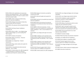
![Dubai Building Code Part G: Incoming utilities
G 14
IEC 61921, Power capacitors – Low voltage power
factor correction banks
NFPA 70, National electrical code
Ref. G.2 INSTITUTION OF ENGINEERING AND
TECHNOLOGY, 2018. Electrician’s guide to the
building regulations. 5th edition. Stevenage: IET.
Ref. G.3 INSTITUTION OF ENGINEERING AND
TECHNOLOGY, 2018. Guidance note 8: Earthing and
bonding. 4th edition. Stevenage: IET.
Ref. G.4 EXECUTIVE COUNCIL OF DUBAI, 2014.
Executive Council Resolution no. (46) of 2014
concerning the connections of generators of electricity
from solar energy to the power distribution system
in the Emirate of Dubai. Dubai: Executive Council of
Dubai.
Ref. G.5 DUBAI ELECTRICITY AND WATER
AUTHORITY. Publications and resources [online
database]. Available from: www.dewa.gov.ae/en/
consumer/solar-community/publications-resources.
Ref. G.6 DUBAI ELECTRICITY AND WATER
AUTHORITY. Technical publications and resources
[online database]. Available from: www.dewa.gov.ae/
en/builder/useful-tools/tech-publications-resources.
Ref. G.7 DUBAI ELECTRICITY AND WATER
AUTHORITY, 2016. Standards for distributed
renewable resources generators connected to the
distribution network. 2nd edition. Dubai: DEWA.
G.3.3 Water
Ref. G.8 Dubai Electricity and Water Authority
(DEWA). Circulars and Regulations [online database].
Available from: www.dewa.gov.ae/en/builder/useful-
tools/dewa-circulars.
G.3.4 District cooling
Ref. G.9 District cooling Providers’ technical guidance
documentation as supplied by the relevant Providers,
which include:
a) Emaar District Cooling;
b) Tabreed;
c) Empower;
d) Emicool.
G.3.5 Telecommunications
G.3.5.1 Essential reading
BS EN 13501-6, Fire classification of construction
products and building elements – Classification using
data from reaction to fire tests on power, control and
communication cables
IEC/EN 60332-1-2, Tests on electrical and optical
fibre cables under fire conditions – Tests for vertical
flame propagation for a single insulated wire or cable –
Procedure for 1 kW pre-mixed flame
ISO/IEC 11801-1, Information technology – Generic
cabling for customer premises – Part 1: General
requirements
ISO/IEC 11801-2, Information technology – Generic
cabling for customer premises – Part 2: Office
premises
ISO/IEC 11801-3, Information technology – Generic
cabling for customer premises – Part 3: Industrial
premises
ISO/IEC 11801-4, Information technology – Generic
cabling for customer premises – Part 4: Single-tenant
homes
ISO/IEC 11801-6, Information technology – Generic
cabling for customer premises – Part 6: Distributed
building services
ISO/IEC 14763-1, Information technology –
Implementation and operation of customer premises
cabling – Part 1: Administration
ISO/IEC 14763-2, Information technology –
Implementation and operation of customer premises
cabling – Part 2: Planning and installation
ISO/IEC 14763-3, Information technology –
Implementation and operation of customer premises
cabling – Part 3: Testing of optical fibre cabling](https://image.slidesharecdn.com/dubaibuildingcodeenglish2021editionak-231227052107-72adb61a/85/Dubai-Building-Code_English_2021-Edition_AK-pdf-416-320.jpg)
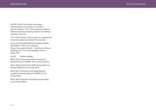
![Dubai Building Code Part G: Incoming utilities
G 16
G.4 Design, erection and installation of electrical systems
G.4.1 General
Sections G.4 to G.7 outline the requirements for
the design of electrical installations. They are based
on the latest edition of BS 7671 and Institution of
Engineering Technology (IET) documents
[Ref. G.2 and Ref. G.3].
11 kV medium voltage (MV) network installations
shall meet the requirements of G.7. For specific
requirements beyond the scope of G.7, the project shall
be referred to DEWA at the concept design stage.
Sections G.4 to G.7 are not intended to:
a) take the place of a detailed specification;
b) instruct untrained persons; or
c) provide for every circumstance.
Where a situation arises that is not covered or allowed
for within these sections, DEWA shall be consulted to
obtain further clarity and guidance.
G.4.2 Electrical supply
The nominal electric supply voltage from DEWA (see
IEC 60038) is 230/400 V ± 10%, 50 Hz, three-phase,
4-wire with separate neutral and protective conductor
(generally metallic armour of the DEWA service cable).
The neutral is solidly earthed at DEWA’s substations
and shall not be earthed elsewhere in the consumer’s
electrical installations. The design fault level within the
substation is 40 kA (fault duration 1 s), except for fuse
protected equipment/circuits.
All equipment, apparatus, materials and accessories
used in electrical installations shall be designed and
rated for operation on this electric supply. Overload,
short-circuit and earth leakage protective devices shall
be provided. Depending on the design of consumer
installations, protective devices shall also be provided
to protect against the following as required:
a) over voltages;
b) fluctuations;
c) transients and harmonics;
d) loss of one or more phases;
e) unforeseen interruptions.
NOTE: The earth leakage current may have a capacitive
component, including that resulting from the deliberate
use of capacitors.
G.4.3 Incoming supply and metering
Before commencing building design, the consumer
shall obtain confirmation of the availability of a power
supply from DEWA.
NOTE 1: Power supply from DEWA’s network is subject
to all applicable terms and conditions as issued by
DEWA.
The consumer shall protect all elements of DEWA
installations provided for and within the premises. Any
violation, defect or damage to DEWA lines, equipment
or metering shall be reported to DEWA immediately.
Where the total connected load (TCL) exceeds
400 kW, provision shall be made within the building or
plot for a DEWA substation.
NOTE 2: In some circumstances a DEWA substation
might be required for connected loads less than
400 kW.
Meters shall be installed to measure and record the
electricity demand and consumption of the facility. All
meters shall conform to DEWA specifications and be
approved by DEWA.
Tariff metering shall be in accordance with G.4.5.
When a building tariff meter is not present, sub
meters shall be installed for each individual tenancy
in the building. These submeters shall be for demand
management and electricity cost allocation purposes
only. Virtual meters using run-hours shall not be used
as submeters.](https://image.slidesharecdn.com/dubaibuildingcodeenglish2021editionak-231227052107-72adb61a/85/Dubai-Building-Code_English_2021-Edition_AK-pdf-418-320.jpg)
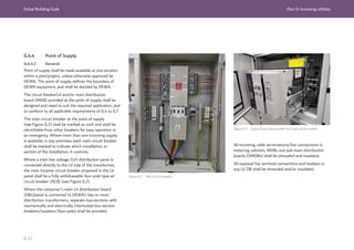
![Dubai Building Code Part G: Incoming utilities
G 18
G.4.4.2 Switchgear locations
The main electrical switchroom shall be located near
to the plot entrance, on the ground floor. Where a
substation is provided within the building, the main
electrical switchroom shall be provided in the ground
floor area adjacent to the transformer room.
The consumer’s MDBs, SMDBs and final DBs shall
all be installed in locations to which access is always
available. The minimum dimensions for safe access
shall be in accordance with Figure G.3.
The mounting height [to the top of the board(s)] shall
normally be 2 m from the ground/floor level.
All main electrical switchrooms, and other sub-
electrical switchrooms in which capacitor banks are
installed, shall be air-conditioned. Non-air-conditioned
electrical rooms shall be ventilated and provided with
heavy duty exhaust fans and metallic louvered doors,
as applicable.
As required by Table 1.9, Ch. 1 of UAE FLSC [Ref. G.1],
interior electrical rooms shall be separated from the
rest of the building by a 2 h fire rated enclosure. If the
access door to the room opens to the exterior then it
can be louvered. Where the access door opens to the
interior of the building it shall be 90 min fire rated
without louvers.
Figure G.3 Layout of main electrical switchroom with one cubicle type LV switchboard/panel
Key
01: LV switchboard/panel
02: Capacitor bank
03: SMDB (sample)
04: kWh meters
05: Non-maintained, minimum
3 h rated, self-contained
emergency light
06: Light fitting
07: Non-combustible door in
an exterior wall and 90 min
fire resistance rated, non-
combustible, non-louvered door
in an interior wall
NOTE: The minimum clear space
shown at the sides and rear of
the panel is for switchboards
with rear access requirements
only.
An adequate level of illumination shall be provided to
facilitate safe operation at all times. All electrical rooms
shall be provided with non-maintained emergency
lighting in accordance with Ch. 6 of UAE FLSC [Ref. G.1].
Door openings to electrical switchrooms shall meet the
following requirements.
a) The door shall open outwards in the direction of
egress.
b) The opening shall be kept free from obstructions.
c) The door shall not open towards a driveway,
staircases and steps, or other areas of people or
traffic movement.
1,500
1,500](https://image.slidesharecdn.com/dubaibuildingcodeenglish2021editionak-231227052107-72adb61a/85/Dubai-Building-Code_English_2021-Edition_AK-pdf-420-320.jpg)
![Dubai Building Code Part G: Incoming utilities
G 19
A minimum illumination of 500 lux shall be provided to
facilitate safe operation at all times.
Incoming supply cables to the consumer’s MDB(s)
shall be completely segregated and identified from the
consumer’s cables.
Electrical switchrooms shall not be located below or
beside the following wet areas:
1) bathrooms;
2) toilets;
3) kitchens;
4) pantries;
5) storage tanks;
6) air conditioning chillers or other liquid/hazardous
materials.
Water pipes shall not be installed within or on electrical
switchroom walls.
G.4.4.3 Main electrical switchroom
The dimensional layout of electrical switchrooms shall
be maintained as shown in Figure G.3 for a single LV
panel, Figure G.4 for switchrooms containing two
freestanding LV panels or Figure G.5 for switchrooms
containing wall mounted LV panels. The electrical
switchroom shall not be used for storage of any
equipment, material, etc.
Figure G.4 Layout of main electrical switchroom with two cubicle type switchboards/panels
NOTE: The minimum clear space shown at the sides and rear of the panel is for switchboards with rear access
requirements only.
Key
01: LV switchboard/panel
02: Capacitor bank
03: SMDB (sample)
04: kWh meters
05: Non-maintained, minimum
3 h rated, self-contained
emergency light
06: Light fitting
07: Non-combustible door in
an exterior wall and 90 min
fire resistance rated, non-
combustible, non-louvered door
in an interior wall
As required by Table 1.9, Ch. 1 of UAE FLSC [Ref. G.1],
interior electrical rooms shall be separated from the
rest of the building by a 2 h fire rated enclosure. If the
access door to the room opens to the exterior then it
can be louvered. Where the access door opens to the
interior of the building it shall be 90 min fire rated
without louvers.
1,200
1,500
1,500](https://image.slidesharecdn.com/dubaibuildingcodeenglish2021editionak-231227052107-72adb61a/85/Dubai-Building-Code_English_2021-Edition_AK-pdf-421-320.jpg)
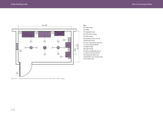
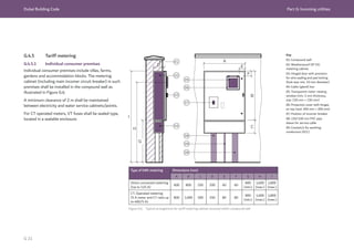
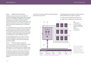
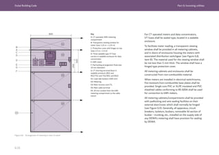
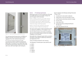
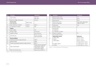
![Dubai Building Code Part G: Incoming utilities
G 26
Table G.3 Ambient design conditions for Dubai
G.4.6 Ambient design conditions
All equipment, apparatus, materials and accessories
used in electrical installations shall be suitable for
the purpose intended and capable of operating with
satisfactory performance in the climatic conditions
described in Table G.3.
Parameter Condition
Altitude Sea level (coastal)
Maximum outdoor ambient temperature
(shade):
48 °C
Minimum ambient air temperature 2.8 °C
Maximum ambient air temperature 48 °C
Maximum average temperature
over 24 h
37.8 °C
Maximum average over temperature
one year
26.9 °C
Relative humidity 100% (max.)
Thunderstorms per year Occasional
Earthquake loading 0.07 g
Wind speed 45 m/s at 10 m height
Ground temperature 40 °C
Soil thermal resistivity
2.0 °C/m/w at depth
of 0.9 m
NOTE: Heavy condensation and sandstorms also prevail
G.4.7 Cables and conductors
G.4.7.1 General
For general purposes and in normal situations,
LSF/XLPE insulated, stranded copper conductor cables
shall be used for all fixed wiring installations. The
cables shall be appropriate to the building type and
conform to the respective standard from the
following list:
a) BS 5467;
b) BS 6004;
c) BS 6724;
d) BS 7211;
e) BS 7629-1;
f) BS 7846;
g) BS 7889;
h) BS 8436.
In certain circumstances, PVC insulated cabling may
be used for general purpose installations, subject to
approval by DEWA.
In flammable/explosive situations, cables shall be
selected in accordance with the requirements of NFPA
70, as required by Ch. 10 of UAE FLSC [Ref. G.1].
Flexible cables and cords for use in electrical
installations shall be LSF insulated and sheathed,
stranded copper conductors conforming to BS 7211.
Cables for connection between ceiling rose and
luminaire for pendant type light fittings and for
enclosed luminaires shall be heat resistant silicone
rubber insulated with stranded copper conductor
conforming to BS EN 50525.
For elevators and similar applications, rubber insulated
or PVC insulated flexible cables conforming to BS EN
50214 shall be used.
kWh meter tails shall normally be single core PVC
insulated and sheathed cables conforming to BS 6004.
The cables used for control, relays, instrument
panels, etc. shall conform to BS 6231. Single core
cables armoured with steel wire or tape shall not be
used for AC circuits.
G.4.7.2 Minimum size of conductors
The size of conductor used for lighting circuits shall be
not less than 2.5 mm2
.
The size of conductor used for utility sockets shall be
not less than 4 mm2
.](https://image.slidesharecdn.com/dubaibuildingcodeenglish2021editionak-231227052107-72adb61a/85/Dubai-Building-Code_English_2021-Edition_AK-pdf-428-320.jpg)
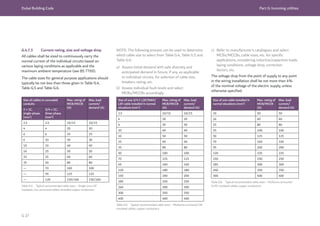
![Dubai Building Code Part G: Incoming utilities
G 30
Parameter Specification
I. Reference standards BS EN 61439/IEC 61439
II. Rating of incoming supply 200 A [ ]
300 A [ ]
400 A [ ]
800 A [ ]
1600 A [ ]
2,500 A [ ]
Breaker/isolator +
(+On-load)
Breaker [ ]
Isolator [ ]
III. Construction
1. Mounting Wall [ ]
Floor [ ]
Pedestal [ ]
...................................[ ]
2. Degree of protection of the enclosure for
installation
Indoor-IP41/42 [ ]
Outdoor-IP54/55 [ ]
...................................[ ]
3. Painting/finish (internal/external) Stove enamelled [ ]
Epoxy [ ]
Polyester [ ]
Galvanized [ ]
...................................[ ]
4. Front cover (+neoprene) Hinged [ ]
Bolted [ ]
Panel lock [ ]
Gasketted+ [ ]
Table G.9 Specification of MDBs/SMDBs
Parameter Specification
5. kWh meter reading provision Glass window [ ]
Gasketted [ ]
6. Cable tray Top [ ]
Bottom [ ]
Top and bottom [ ]
7. Ventilation Natural via louvers [ ]
Mechanical exhaust/supply [ ]
...................................[ ]
8. Sealing/pad locking provision
IV. Internal layout/arrangement and fault rating
1. Segregation of live parts: Incoming supply
terminals/lugs
Barrier [ ]
Shroud [ ]
Firmly secured [ ]
Separately mounted and removable by tool [ ]
Busbar, tap-out connections and terminals
(separate and independent of each other)
Firmly secured [ ]
Separately mounted and removable by tool [ ]
Neutral and earth busbars and terminals
Separately mounted with adequate working
clearances/spacing from incoming supply
terminals/lugs [ ]
2. Arrangement of busbars and tap-out
connections to outgoing circuit breakers
Rigid, firmly secured, supported, direct and as
short as possible [ ]
Adequately sized [ ]
Min. number of bolted joints [ ]
3. Rating/size of phase and neural busbars and
terminals (at max. 50 °C ambient)
Rated for max. 70 °C internal ambient, consistent
with the rated incoming supply breaker/isolator
[ ]
Tinned electrolytic copper [ ]](https://image.slidesharecdn.com/dubaibuildingcodeenglish2021editionak-231227052107-72adb61a/85/Dubai-Building-Code_English_2021-Edition_AK-pdf-432-320.jpg)
![Dubai Building Code Part G: Incoming utilities
G 31
Parameter Specification
4. Rating of main incomer and busbars DEWA’s ...................................[ ]
- Min. fault rating
40 kA [ ]
...................................[ ]
5. Min. and max. rating of outgoing circuit
breakers
...................................[ ]
- Min. fault rating
35 kA [ ]
...................................[ ]
6. Provision of min. working clearance/space for
incoming supply cable terminations
200 A
300 A
400 A
200 A/300 A/400 A incomers (mm)
800 A/1,600 A/2,500 A incomer (mm)
Outgoing circuit cables
250 [ ] 350 [ ] 450 [ ]
750 [ ]
With/without cable box [ ]
Adequate [ ]
7. Provision of supports/facility for dressing/
clamping outgoing circuit cables
Channels [ ]
Trunking [ ]
...................................[ ]
Max. height 2 m (From FFL) [ ]
8. Operational access/convenience for switchgear
incoming supply circuit breaker/isolator outgoing
circuit breaker
From outside of hinged door/bolted cover [ ]
Restricted/lockable [ ]
9. Maintenance access/replacement convenience
for switchgear components
Breaker [ ]
CTs [ ]
4 kWh meter [ ]
Gland plate [ ]
10. Provision for termination of Cu./XLPE/
AWA(S.C.)
Non-ferrous glands plate [ ]
Parameter Specification
V. Identification
1. Rating of incoming supply and outgoing circuit
breakers:
(For the specified rating – refer approved single
line
diagram no.: ................................)
Thermal [ ]
Discrimination [ ]
Fault [ ]
2. Type of circuit breakers:
Incoming
Outgoing
ACB [ ] MCCB [ ] F/S [ ]
MCCB [ ] F/S [ ] C/L MCCB [ ]
3. Terminal ferrules for control/auxiliary circuits
kWh meter [ ] Indicating instruments[ ]
Other...................................[ ]
VI. Earthing Compliance with G.4.19..................... [ ]
1. Rating/size of earth busbar and terminals
Adequate, consistent with the min. fault rating
specified under IV.4 and IV.5 [ ]
Adequate no. and size to terminate main and
circuits ECCs [ ]
2. Earthing of conductive parts
Enclosure [ ]
Hinged door [ ]
Cable glands [ ]
3. Termination of ECCs Copper lugs [ ]
VII. Metering Compliance with G.4.5................... [ ]
1. Standard indicating instruments
Volt meter with selector switch [ ]
Power factor (PF) meter [ ]
Ammeter [ ]
Current transformers [ ]
Indicating lamps [ ]
2. kWh meters/CTs Tested and calibrated in DEWA [ ]
Table G.9 Specification of MDBs/SMDBs (continued)](https://image.slidesharecdn.com/dubaibuildingcodeenglish2021editionak-231227052107-72adb61a/85/Dubai-Building-Code_English_2021-Edition_AK-pdf-433-320.jpg)
![Dubai Building Code Part G: Incoming utilities
G 32
Parameter Specification
3. Wiring/connections of CT meter “Load” side of Incoming supply breaker [ ]
4. Protection of CT meter wiring (Allow six spare
fuse cartridges in the MDB)
Current coil [ ]
Voltage coil [ ]
“Sealed” type fuse [ ]
Heat resistant/High voltage grade [ ]
5. Mounting height from FFL
Max. 2 m. [ ]
Min. 0.8 m. [ ]
6. Mounting (if door/cover mounted) Hinged door mounted [ ]
7. CTs for tariff metering
Exclusive [ ]
Accuracy class 0.2S [ ]
Matching ratio [ ]
VIII. Tests/Certification
1. Type test
2. Routine tests and checks:
Visual checks;
Screwed/bolted connections;
Operational checks;
Dielectric test.
As specified by the Consultants/Owner [ ]
Certificate for review/reference [ ]
Compliance with specifications [ ]
Tightness [ ]
Mechanical/Electrical [ ]
2,500/2,125 V (85%) [ ]
The following shall be provided in MDBs with a rating of 200 A or more, and may be
provided in SMDBs if appropriate:
a) voltmeter (with R-Y-B “OFF” selector switch);
b) ammeter (with CTs as applicable);
c) maximum demand indicator/recorder;
d) PF meter;
e) indicating lamps;
f) associated protective devices.
The switchgear, equipment and accessories shall conform to the following standards
as applicable:
1) BS EN 60670;
2) BS EN 60898-1;
3) BS EN 60947;
4) BS EN 61439;
5) IEC 61439.
G.4.12.2 Final distribution boards
DBs installed for connection of the final circuits within electrical installations shall be
factory-built conforming to BS EN 61439/IEC 61439. An integral isolator shall be
provided for isolation of the incoming supply.
The circuit breaker accessories shall conform to the standards as specified by the
project designer(s).
Rewireable type fuses shall not be used in any wiring installation. Table G.10 may
be used to indicate the preferred details and parameters of the equipment and
components in final DBs for an individual application.
Table G.9 Specification of MDBs/SMDBs (continued)](https://image.slidesharecdn.com/dubaibuildingcodeenglish2021editionak-231227052107-72adb61a/85/Dubai-Building-Code_English_2021-Edition_AK-pdf-434-320.jpg)
![Dubai Building Code Part G: Incoming utilities
G 33
Parameter Specification
I. Reference standards BS EN 61439, BS EN 60947, IEC 61439
II. Rating of incoming supply 40 A [ ]
60 A [ ]
100 A [ ]
125 A [ ]
.................... [ ]
(+On-load) Breaker [ ]
Isolator [ ]
III. Construction
1. Mounting Wall [ ]
Pedestal [ ]
Surface [ ]
Recessed [ ]
2. Degree of protection of the enclosure for
installation
Indoor-IP41/42 [ ]
Outdoor-IP54/55 [ ]
...................................[ ]
3. Painting/Finish (internal/external) Stove enamelled [ ]
Epoxy [ ]
Polyester [ ]
Galvanized [ ]
...................................[ ]
4. Front cover (+neoprene) Hinged [ ]
Bolted [ ]
Panel lock [ ]
Gasketted+ [ ]
Table G.10 Specification of DBs
Parameter Specification
5. Cable tray/conduit entry Top [ ]
Bottom [ ]
Top and bottom [ ]
6. Assembly Factory assembled [ ]
...................................[ ]
IV. Internal layout/arrangement and fault training
1. Segregation of live parts:
Incoming supply terminals/lugs
Barrier [ ]
Shroud [ ]
Firmly secured [ ]
Separately mounted and removable by tool [ ]
Busbar, tap-out connections and terminals
(Separate and independent of each other)
Barrier [ ]
Firmly secured [ ]
Separately mounted and removable by tool [ ]
Neutral and earth busbars and terminals Separately mounted with adequate working
clearances/spacing from incoming supply
terminals/lugs [ ] and outgoing terminals of
MCBs/FS [ ]
2. Arrangement of busbars and tap-out
connections to outgoing circuit breakers/neutral
busbars
Segregated for each:
Group of MCBs/TP ways [ ]
ELCB Section [ ]
Rigid, firmly secured, supported, direct and as
short as possible [ ]
Adequately sized [ ]
Min. number of bolted joints [ ]
Min. number of looped connections [ ]](https://image.slidesharecdn.com/dubaibuildingcodeenglish2021editionak-231227052107-72adb61a/85/Dubai-Building-Code_English_2021-Edition_AK-pdf-435-320.jpg)
![Dubai Building Code Part G: Incoming utilities
G 34
Parameter Specification
3. Rating/size of phase and neural busbars and
terminals (at max. 50 °C ambient)
Rated for max. 70 °C internal ambient, consistent
with the rated incoming supply breaker/isolator
[ ]
Tinned electrolytic copper [ ]
...................................[ ]
4. Min. fault rating of circuit breakers 6 kA (as per designed downstream short-circuit
current) [ ]
5. Provision of supports/facility for dressing
clamping outgoing circuit cables
Channels [ ]
Trunking [ ]
..................... [ ]
6. Operational access/convenience for switchgear.
Incoming supply circuit breaker/isolator
Outgoing circuit breakers
Max. height 1.8 m (from FFL) [ ]
From outside of hinged door/bolted cover [ ]
Restricted/lockable [ ]
7. Maintenance access/replacement convenience
for switchgear components
Breaker(s) [ ]
Isolators [ ]
ELCB/s [ ]
UV relays [ ]
8. Provision for termination of PVC/SWA/PVC/
XLPE/SWA/PVC cables
Gland plate [ ]
Cable gland [ ]
9. ELCBs/RCCBs Window air conditioning [ ]
Split air conditioning [ ]
Lighting [ ]
Small power [ ]
Others..................... [ ]
10. UV Relays with auto-reset timer Window air conditioning [ ]
Split air conditioning [ ]
Others.................... [ ]
Parameter Specification
V. Identification
1. Rating of incoming supply and outgoing circuit
breakers:
(For details of the rating specified – refer to
approved SLD/distribution schedules)
Thermal [ ]
Fault [ ]
Discrimination [ ]
Type of circuit breakers: Incoming Outgoing C/L-
Current Limit
Isolator [ ]
MCCB [ ]
C/L MCCB [ ]
C/L MCCB [ ]
F/S [ ]
C/L [ ]
For general loads, Type 1/L[ ]
For motor load, Type 2/G [ ]
2. Colour codes for internal, main circuits wiring:
Phase
Neutral
Earth
Red/yellow/blue [ ]
Black [ ]
Green and yellow [ ]
3. Terminal ferrules for control/auxiliary circuits Indicating instruments [ ]
Others..................... [ ]
4. Permanent labels, engraved, “Traffolite” or
similar
Board designation [ ]
Controls [ ]
Circuit designation [ ]
Indications [ ]
Warning notice(s) [ ]
ELCB/UV relay section [ ]
Table G.10 Specification of DBs (continued)](https://image.slidesharecdn.com/dubaibuildingcodeenglish2021editionak-231227052107-72adb61a/85/Dubai-Building-Code_English_2021-Edition_AK-pdf-436-320.jpg)
![Dubai Building Code Part G: Incoming utilities
G 35
Parameter Specification
VI. Earthing Compliance with G.4.19..................... [ ]
1. Rating/size of earth busbar and terminals Adequate, consistent with the min. fault rating
specified under IV.4 [ ]
Adequate no. and size to terminate main and
circuits ECCs [ ]
2. Earthing of conductive parts: Enclosure [ ]
Hinged door [ ]
Cable glands [ ]
3. Termination of ECCs Copper lugs [ ]
VII. Tests/certification
1. Type test
2. Routine tests and checks:
Visual checks
Screwed/bolted connections;
Operational checks
Dielectric test
As specified by the Consultants/Owner [ ]
Certificate for review/reference [ ]
Compliance with specifications [ ]
Tightness [ ]
Mechanical/electrical [ ]
2,500/2,125 V (85%) [ ]
Table G.10 Specification of DBs (continued)
G.4.13 Apparatus and accessories
G.4.13.1 Switches
Switches provided for local isolation of electric supply to individual apparatus and/or
circuits shall conform to BS EN 60669. The rating of the switches shall be selected
based on individual applications, such as for resistive or inductive loads. The current
rating shall be not less than 5 A.
Switches shall be metal clad when used within industrial installations.
Switches installed for control of discharge lighting shall have a minimum current
rating that is twice the steady state continuous current of the circuits.
For large groups of lighting, a gang switch shall be provided with phase barrier inside
the switch boxes.
For outdoor locations, switches with weather protection classified as IP55 in
accordance with BS EN 60529 shall be used.
For areas with a high risk of fire or explosion, gas sealed switches conforming to
BS EN 60079 shall be used.
For appliances rated 20 A and above, and where visual indication of the presence of
power is desired, a DP switch with neon indicator shall be provided.](https://image.slidesharecdn.com/dubaibuildingcodeenglish2021editionak-231227052107-72adb61a/85/Dubai-Building-Code_English_2021-Edition_AK-pdf-437-320.jpg)
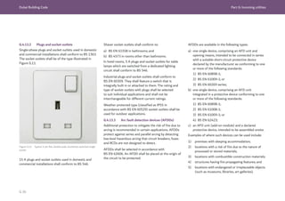
![Dubai Building Code Part G: Incoming utilities
G 37
G.4.13.4 Surge protection devices (SPDs)
Surge protection devices shall be implemented on electrical distribution systems
within new buildings. SPDs shall have the necessary capability to deal with the
current levels and durations involved at the point of installation.
For the protection of AC power circuits, SPDs are allocated a type number. The
number corresponds to a test class from the BS EN 61643 series as follows, and as
illustrated in Figure G.12:
a) type 1 – only used where there is a risk of direct lightning current and typically
used at the origin of an installation;
b) type 2 – used at DBs;
c) type 3 – used at or near equipment.
Figure G.12 SPD installation location based on type
Figure G.13 Cooker control unit installed within 2 m of appliance
(© Institution of Engineering and Technology. Figure based on Figure
4.4 in Institution of Engineering and Technology, 2018. Electrician's
guide to the building regulations [Ref. G.2])
01
02
03
Key
01: Type 1 Main switchboard
02: Type 2 Sub distribution
03: Type 3 Final equipment
Key
01: Control switch to be located
within 2 m from controlled appliance
02: Electric hob
03: Electric oven
04: Consumer unit
G.4.13.5 Cooker control units
All stationary cooking appliances in domestic premises shall have a cooker control
switch. The switch shall conform to BS 4177 and be located separately from the
appliance (see Figure G.13). The cooking appliance shall incorporate an integral
earthing terminal.
The cooker control switch shall be two-pole (for a single-phase appliance) or four-
pole (for a three-phase appliance). It shall be connected to a separate final sub-circuit
from the DB, through a 100 mA ELCB.](https://image.slidesharecdn.com/dubaibuildingcodeenglish2021editionak-231227052107-72adb61a/85/Dubai-Building-Code_English_2021-Edition_AK-pdf-439-320.jpg)
![Dubai Building Code Part G: Incoming utilities
G 38
Cooker control units incorporating a general purpose
socket outlet shall be avoided, to allow grouping of
general socket outlets in a separate 30 mA RCD/ELCB
section.
The breaker rating and wire size shall be selected to be
compatible with the connected load of the appliance.
G.4.13.6 Kitchen appliances
Electrical appliances used in consumer installations (such as water heaters, cookers, hot plates, etc.) shall generally
conform to BS EN 60335. Figure G.14 illustrates the typical setting out details of a kitchen.
Figure G.14 Cooker and kitchen typical installation setting out details (© Institution of Engineering and
Technology. Figure based on Figure 5.2.2 in Institution of Engineering and Technology, 2018. Electrician's guide
to the building regulations [Ref. G.2])
Key
01: No sockets within 300 mm
of edge of sink
02: No sockets or accessories
above gas or electric hobs
03: Cooker switch
04: Dishwasher
05: Fridge
06: 150 vs 250 Cooker
connection](https://image.slidesharecdn.com/dubaibuildingcodeenglish2021editionak-231227052107-72adb61a/85/Dubai-Building-Code_English_2021-Edition_AK-pdf-440-320.jpg)
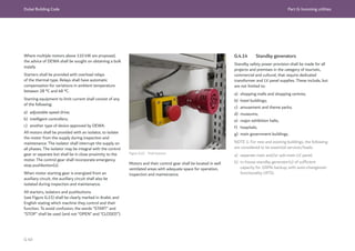
![Dubai Building Code Part G: Incoming utilities
G 41
The following loads shall be served by standby
generators:
1) elevators, escalators, security systems, CCTV,
alarm systems, BMS systems, stairways,
entrances, control rooms, data centres, electrical
rooms, generator rooms, etc.;
2) minimum 20% of lighting installations in the
landlord areas (corridors, public lobbies, assembly
points, reception, underground parking, etc.).
NOTE 2: For new buildings, the following are
considered to be non-essential services/loads:
a) additional ACB(s) as incomer with auto-changeover
facility (motorized ACB operation) to connect to
external mobile generator for all non-essential LV
panels;
b) access for transportation and stationing of the
mobile generators, intake arrangements for
cabling and connections, identification labels and
notices for connection of the generator during
emergencies.
NOTE 3: The requirements listed above are for the
standby provision of electrical power under unforeseen
power interruptions only. Emergency and standby
power requirements of fire and life safety systems
are covered in Ch. 6 to Ch.10 of UAE FLSC [Ref. G.1].
Emergency generators for operational continuity can
be shared with those required by UAE FLSC provided
that the shared generator(s) meets the requirements
of both codes.
Generator rooms shall be 2 h fire rated to conform
to Table 1.9, Ch. 1 of UAE FLSC [Ref. G.1]. Exterior
walls do not need to be fire rated unless there is a
risk of exterior fire spread and the wall is fire rated in
accordance with Ch. 1 of UAE FLSC [Ref. G.1]. Louvers
in fire rated walls are not permitted without opening
protection.
NOTE 4: Installing and connecting standby generators
in the consumer’s installation to maintain power supply
in the event of mains failure is permitted only with
prior approval from DEWA.
NOTE 5: The changeover circuit breaker or isolator
should have four poles for three-phase supply and two
poles for single-phase supply. This ensures that the
phases and neutral of the two systems remain separate
and distinct.
NOTE 6: The installation should be carried out in
such a way that there is no possibility of paralleling
generator supply with DEWA supply.
NOTE 7: Adequate mechanical and electrical interlock
should be provided between the incomer circuit
breakers or isolators of both the generator and DEWA
supplies. Full details of the equipment, including details
of the essential loads, and circuit and wiring diagrams,
should be submitted to DEWA for approval before
commencement of the works.
NOTE 8: Provision for connecting a mobile generator
with incomer rating 2,500 A/1,600 A, to maintain
power supply in the event of mains failure, should be
included in the MDB/LV panel. The circuit breaker
should be a four-pole type. Adequate mechanical and
electrical interlock should be provided between the
incomer circuit breakers of both the mobile generator
and DEWA supply.
NOTE 9: The location of main electrical room should
be near to the front entrance/approach road and
sleeves are to be provided for intake generator cables.
This provision is not mandatory for the main LV panel
connected with standby generator in auto/manual
changeover mode.
G.4.15 Power to fire pumps
Table 9.3, Ch. 9 of UAE FLSC [Ref. G.1] requires
a direct power supply from the utility company to
the main electric fire pump and jockey pump via a
dedicated DB located inside the pump room.
NOTE: It is the responsibility of the consumer to
provide this arrangement at the main LV panel.](https://image.slidesharecdn.com/dubaibuildingcodeenglish2021editionak-231227052107-72adb61a/85/Dubai-Building-Code_English_2021-Edition_AK-pdf-443-320.jpg)
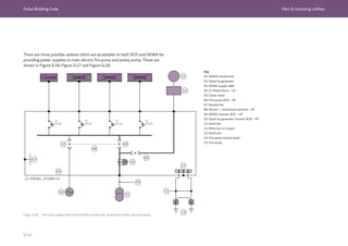
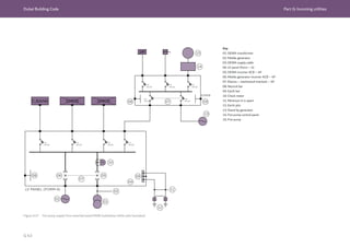
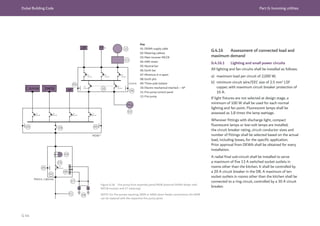
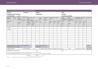
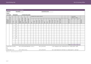
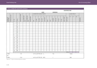
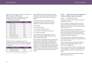
![Dubai Building Code Part G: Incoming utilities
G 51
Draw-wires shall be provided in all concealed conduits (and ducts) with the ends
left free at the outlet boxes for pulling the wiring cables. Permitted cable routes for
concealed cables are illustrated in Figure G.19.
Figure G.19 Permitted cable routes for concealed cables within walls with a depth of less than
50 mm depth. (© Institution of Engineering and Technology. Figure based on Figure 2.3.3 in Institution of
Engineering and Technology, 2018. Electrician's guide to the building regulations [Ref. G.2])
Key
01: No protection needed
02: Protection required unless depth greater than 50 mm
All the trunking and conduit runs shall be free from sharp edges and burrs
throughout their lengths. Suitable grommets and bushes shall be provided at the
terminal outlets.
Trunking and conduit runs shall be supported at regular intervals (see Table G.17 to
Table G.19).
Method of installation Spacing of support (mm)
Steel Rigid PVC
Horizontal 1,500 1,000
Vertical 1,800 1,200
Method of installation Spacing of support (mm)
Steel Rigid PVC
Horizontal 1,200 1,000
Vertical 1,500 1,200
Method of installation Spacing of support (mm)
Overall diameter
20 mm to 40 mm
Overall diameter
>40 mm
Horizontal 350 600
Vertical 600 800
Table G.17 Trunking – Maximum spacing of clips, cleats, saddles or supports
Table G.18 Conduit – Maximum spacing of clips, cleats, saddles or supports
Table G.19 Armoured cables – Maximum spacing of clips, cleats, saddles or supports](https://image.slidesharecdn.com/dubaibuildingcodeenglish2021editionak-231227052107-72adb61a/85/Dubai-Building-Code_English_2021-Edition_AK-pdf-453-320.jpg)
![Dubai Building Code Part G: Incoming utilities
G 52
Entries to trunking shall be placed to prevent the
ingress of water and all dead ends shall be closed. Only
unbroken lengths of trunking shall be used for crossing
partitions and walls.
Where cable trunking passes through walls, floors or
other barriers, it shall be provided with a continuous
cover.
Where cable trunking penetrates fire resistance
rated floors, walls, partitions or ceilings, the openings
remaining after passage of the trunking systems shall
be sealed with an approved fire stopping system in
accordance with Section 3, Ch. 1 of UAE
FLSC [Ref. G.1].
The trunking shall be provided with separate
compartments for the different types of circuits in the
following situations:
a) where a common cable trunking is used for housing
both power and communication circuits; or
b) for housing circuits operating at different voltages.
All bends, tees and other accessories of cable trunking
shall be of substantial sections and of the same quality
as the trunking itself.
The different sections of trunking shall be bonded by
copper links. Trunking shall not be used as ECC.
The minimum internal radius of any bend or elbow
fitting in a conduit shall be 2.5 times the diameter of
the conduit, as shown in Figure G.20.
Figure G.20 Minimum internal radius of conduit elbow fitting
All terminal and intermediate ends of PVC conduits
shall be firmly secured with suitable adhesives as
recommended by the manufacturer.
Circuit wires shall be bunched and installed in vertical
trunking runs. They shall be clamped/secured within
the trunking at regular intervals not exceeding 2 m, and
at the terminal ends.
Standard conduit boxes, draw-in boxes and mounting
boxes of light fittings and appliances shall be fixed
to the building structure independently of the wiring
conduits.
All exposed threads, tool-marks or visible damage to
the protective finish of the steel trunking and conduits
shall be coated with zinc rich paint immediately after
installation.
Suitable expansion couplers shall be provided in all
trunking and conduit runs at the expansion joints in
the building structure. They shall also be provided at
regular intervals in all runs exceeding 7 m in length or
as recommended by the manufacturer.
Suitable purpose-made boxes with adaptors, ceiling
roses, etc. shall be provided at all individual outlet
points of the wiring installations.
Light fittings used to house tungsten filament and
halogen lamps shall be segregated protected by PVC
sheathing and terminal outlet boxes such as to prevent
degradation due to the associated high temperatures.
Conduit runs concealed within the building structure
shall be provided with not less than 10 mm of screed
cover.
When the trunking and conduit runs are installed
with chases in the building structure, they shall be
firmly fixed at regular intervals in accordance with the
manufacturer’s recommendations, using purpose-made
crimpers and/or saddles.
The standard conduit boxes, draw-in boxes, floor-
outlet boxes, etc. shall be installed with the cover/lid
flush with the outer finish of the building structure
(see BS 4662, BS 5733, BS EN 61535).](https://image.slidesharecdn.com/dubaibuildingcodeenglish2021editionak-231227052107-72adb61a/85/Dubai-Building-Code_English_2021-Edition_AK-pdf-454-320.jpg)
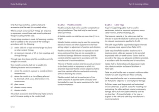
![Dubai Building Code Part G: Incoming utilities
G 54
Cable trays shall be installed as complete systems with
bends and other accessories. Each run of cable trays
shall be completed before the installation of cables. All
sharp edges, burrs and projection shall be removed,
and the tray shall be finished smooth to prevent injury
to cables.
Metallic cable trays shall be bonded together using
copper links, but shall not be used as an ECC.
Cable trays shall be installed in such a way as to
provide ease of access to cables through the route.
Where cable trays penetrate fire rated floors, walls,
partitions or ceilings, the openings remaining after
passage of the wiring systems shall be sealed with
an approved fire stopping system in accordance with
Section 3, Ch. 1 of UAE FLSC [Ref. G.1].
G.4.18 Design criteria for the installation
of cables, equipment, accessories and wiring
systems
G.4.18.1 Armoured cables
Armoured cables shall be installed in one of the
following ways:
a) directly buried in the ground;
b) drawn through ducts;
c) laid in concrete trenches;
d) cleated to a wall;
e) mounted on cable trays.
Cables shall be installed and used in association with
other equipment in accordance with BS 7671. In
environments or installations not described within the
DBC, the appropriate regulations and standards shall
be observed.
The current-carrying capacity of cables shall be
determined after applying suitable correction factors
based on the installation method of the cables.
Cables shall be selected ensuring voltage drops within
the limit described in G.4.7.3.
Only armoured cables shall be used for underground
installations. Precautions shall be taken to avoid
mechanical damage to the cables before and during
installation. Cables shall be laid as shown in
Figure G.21. Where protective covers are required, they
shall be centred over the cables, throughout
their length.
Figure G.21 Typical armoured cable installation below ground
Key
01: Ground
02: Warning tape at 300 mm below ground
03: 50 mm overlap on either side
04: Armoured cable at 900 mm below ground
05: 150 mm impervious soil layer](https://image.slidesharecdn.com/dubaibuildingcodeenglish2021editionak-231227052107-72adb61a/85/Dubai-Building-Code_English_2021-Edition_AK-pdf-456-320.jpg)
![Dubai Building Code Part G: Incoming utilities
G 55
Where cables pass underneath driveways or roads,
PVC-U ducts shall be provided with heavy duty (HD)
manhole covers.
Cable routes shall be marked by cable route markers/
marking tape, placed at maximum intervals of
10 m along straight runs and 2 m at deviations.
Route markers shall indicate the voltage level in Arabic
and English, as shown in Figure G.22.
Figure G.23 Cable bending radius
No joints shall be included in any cable runs in the
consumer’s fixed wiring installation.
Where busways penetrate fire rated floors, walls,
partitions or ceilings, the openings remaining after
passage of the wiring systems shall be sealed with
an approved fire stopping system in accordance with
Section 3, Ch. 1 of UAE FLSC [Ref. G.1].
Cable glands used for armoured cables shall be of brass
compression type, conforming to BS 6121, with earth
tags and PVC shroud.
All terminations of cable conductors shall be
mechanically and electrically sound. Terminations shall
be made using a terminal or compression type socket/
lug, approved by DEWA. Terminations shall not impose
any mechanical strain on the terminal or socket/lug.
Separate ECCs shall be installed and terminated for
each feeder/circuit, as specified in G.4.19.
Single core cable shall be arranged in trefoil formation.
Non-ferrous cable gland plate shall be used for
termination of single core armoured cables.
The armour shall be earthed.
No cables shall run in an elevator or hoist shaft unless
the cables are part of the elevator/hoist installation.
Figure G.22 Typical cable route marker (DEWA)
Heavy duty conduit shall be provided for motor
connections, external applications and locations subject
to vibration, risk of mechanical damage or exposure to
moisture.
Cables shall be installed on cable trays at specific
locations and as stipulated in G.4.11.
In the event of crossing or proximity of underground
telecommunication cables and underground power
cables, a minimum vertical clearance of 100 mm shall
be maintained.
For cables in fixed wiring installations, the internal
radius of the bend shall be not less than eight times
the cable diameter (see Figure G.23).](https://image.slidesharecdn.com/dubaibuildingcodeenglish2021editionak-231227052107-72adb61a/85/Dubai-Building-Code_English_2021-Edition_AK-pdf-457-320.jpg)
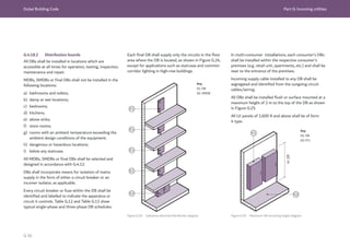
![Dubai Building Code Part G: Incoming utilities
G 57
500 - 1,800
500 - 1,800
01
01
02
03
G.4.18.3 Busbar trunking systems (busways/bus
risers)
Busways shall be installed only where adequate access
is available for inspection and repair throughout their
entire length.
The design, manufacture, testing and performance of
the busbar trunking system shall be in accordance with
BS EN 61439. The IP rating shall be selected based on
the location, as described in BS EN 60529.
Each piece of busbar trunking shall be subject to the
following factory tests:
a) 3.5 kV dielectric test for 4 s;
b) 1,000 V Megger test in accordance with BS 7671.
Test certificates for these tests shall be produced
during DEWA inspection.
The busbars shall be totally enclosed in an
unventilated, low impedance sandwich design. The
busbar trunking shall be sandwiched throughout its
entire length and shall not be flared at tap-points.
Onsite, each piece and run of busbar trunking shall be
Megger tested at 1,000 V before and after installation.
Busbar risers proposed for installation in high-rise
buildings shall be designed in such a way as to ensure
reliability of power supply. In the event of outage of the
respective busbar riser, not more than 12 floors shall
be interrupted.
Connections to switchgear shall have flanged end units
of specific design and shall be manufactured by the
busbar trunking manufacturer.
The busbar trunking shall be aligned and securely
fixed at centres of not more than 1.5 m or as
recommended by the manufacturer. The busbar
trunking manufacturer shall supply galvanized fixing
brackets, comprising hanger clamp, fixing channel and
damping screw, as means of support to take the weight
of the busbar. Additional supports shall be provided
where required and as recommended by the trunking
manufacturer.
The complete busbar trunking system shall be of the
type, size and location indicated in the DEWA approved
drawings.
The busbar shall carry its rated current without
exceeding 55 ºC (or an ambient temperature of 50 ºC
at 90% relative humidity) in any plane without
de-rating and without affecting the DEWA power
supply requirements.
Where a busbar trunking system is installed on the
supply side of any DEWA kWh metering, provision for
sealing by DEWA shall be made as specified in G.4.5.
The phase busbar, neutral bar and earth bar shall be of
copper, identified by colour as given in Table G.8. The
neutral bar shall be of the same cross-section as the
phase busbar.
ECCs and equipotential bonding shall be provided as
specified in G.4.19.
Where the busway passes through fire rated floors,
walls, partitions or ceilings, the openings remaining
after passage of the wiring systems shall be sealed
with an approved fire stopping system in accordance
with Section 3, Ch. 1 of UAE FLSC [Ref. G.1].
Tap-off units installed in a busbar riser at each floor
level shall be at the height shown in Figure G.26. The
tap-off units shall have adequate access for operation,
maintenance and replacement.
Figure G.26 Busbar tap-off mounting height requirement
Key
01: Tap off
02: MDB/SMDB
03: Busbar](https://image.slidesharecdn.com/dubaibuildingcodeenglish2021editionak-231227052107-72adb61a/85/Dubai-Building-Code_English_2021-Edition_AK-pdf-459-320.jpg)
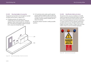
![Dubai Building Code Part G: Incoming utilities
G 60
G.4.19 Earthing and earth leakage
protection
G.4.19.1 General
Earthing systems shall be designed and installed in
such a way that they remain safe and do not endanger
the health and safety of persons or their surroundings.
Every consumer installation shall be provided with
a separate earthing system within the plot limits,
installed and maintained by the consumer.
An earth system shall remain effective throughout the
life of the plant. It is difficult in many cases to perform
of continuity checks after installation; the system shall
therefore be robust and protected from mechanical
damage and corrosion where necessary.
Each consumer’s earthing system shall comprise
the earth electrode(s) main earth lead conductor
connected between the earth electrode(s) and the
consumer’s main earthing terminal(s) or earth busbar.
ECCs shall be provided for every outgoing circuit from
the MDB, SMDB and final DBs, equipotential bonding
of all metalwork and exposed conductive parts and
enclosures, etc. Guidance is available in BS 7430,
BS EN 50522 and IEC 60364.
Selection of the earthing conductor material shall
be based on its compatibility with the material of
the earth electrode. For a conductor installed in the
ground, the corrosive effect of the soil shall also be
taken into account.
The consumer’s earthing system shall be connected
to the DEWA earthing system [either the incoming
supply cable armour or the earth continuity conductor
(ECC), as approved by DEWA].
The following shall have separate earthing networks
and shall not be connected to the main electrical
earthing system:
a) MV networks;
b) LV networks;
c) Extra LV networks;
d) private generators;
e) lightning protection systems.
The earthing system shall be of low electrical
resistance, good corrosion resistance and able to
dissipate high fault current repeatedly.
The consumer main earthing connection shall be
a TN-S system (see Figure G.29). The exposed
conductive parts of all the electrical equipment of the
installation shall be connected by circuit ECCs to the
main earthing terminal. The earth fault loop impedance
shall be sufficiently low for the protective device (fuse,
circuit breaker, RCD) to operate in the required time in
the event of a fault to earth.
Figure G.29 Typical TN-S earthing arrangement (© British Standards Institute. Figure extracted from BS 7671:2018. Permission to reproduce extracts
from British Standards is granted by BSI Standards Limited (BSI). No other use of this material is permitted).
Key
01: Source of energy
02: Protective conductor (PE)
03: Consumers’ installations
04: Source earth
05: Equipment in installation
06: Exposed-conductive-parts](https://image.slidesharecdn.com/dubaibuildingcodeenglish2021editionak-231227052107-72adb61a/85/Dubai-Building-Code_English_2021-Edition_AK-pdf-462-320.jpg)
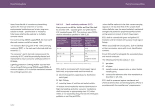
![Dubai Building Code Part G: Incoming utilities
G 64
G.4.19.5 Equipotential bonding
All metalwork of the consumer’s installation, other than current-carrying parts, shall
be provided with equipotential bonding conductors as shown in Figure G.30. This
shall include, but is not limited to:
a) cable armour;
b) metal conduits;
c) metal cable tray/trunking sections;
d) metal accessory boxes;
e) exposed metalworks of consumers’ appliances;
f) apparatus;
g) equipment;
h) machines;
i) building structures;
j) metallic enclosures and parts;
k) metal water pipes.
The cross-sectional area of equipotential bonding conductors shall be selected using
Table G.20.
A main protective bonding conductor shall have a minimum cross-sectional area
not less than half the cross-sectional area required for ECC of the installation, and
not less than 6 mm2
. A maximum cross-sectional area of 25 mm2
is sufficient if
the bonding conductor is of copper or a cross sectional area affording equivalent
conductance in other materials.
The equipotential bonding conductors shall be connected to the main earthing
terminal within the consumer’s wiring installations. The continuity shall be tested and
maintained by the consumer.
Figure G.30 Typical example of main equipotential bonding of services (© Institution of
Engineering and Technology. Figure based on Figure 5.6 in Guidance Note 8: Earthing and
Bonding [Ref. G.3]).
Key
01: Other extraneous conductive part
02: Water installation pipe
03: Circuit protective conductors
04: Gas installation pipe
05: Main protective bonding conductors
06: Earthing conductor
07: Means of earthing](https://image.slidesharecdn.com/dubaibuildingcodeenglish2021editionak-231227052107-72adb61a/85/Dubai-Building-Code_English_2021-Edition_AK-pdf-466-320.jpg)
![Dubai Building Code Part G: Incoming utilities
G 65
G.4.20 Power factor correction, harmonic
and undervoltage (UV) relays
G.4.20.1 PF correction
The PF of every consumer installation shall be within
the range of 0.9 lagging and unity (recommended value
0.95 lagging).
All air-conditioning units/plants/equipment, machines,
motors, light fittings with discharge lamps/mercury
vapour/sodium vapour/fluorescent tubes, etc., shall
be provided with capacitors or other approved means
to achieve and maintain a PF of 0.95 lagging or above,
throughout their normal working range.
For commercial premises that require DEWA service
feeders of 200 A and above, where individual
load compensation cannot be achieved, overall
compensation at main or sub-main distribution levels
shall be provided by incorporating capacitor banks with
automatic regulated steps. For residential premises the
limitation shall be a 400 A feeder.
The PF correction capacitor shall be a dry,
encapsulated, sealed type conforming to IEC 61921.
Capacitors shall be enclosed or guarded to prevent
accidental contact of conducting metal parts with
exposed energized parts, terminals or buses associated
with them.
Capacitors installed for PF correction shall be provided
with the means for automatic, immediate discharge
when the capacitor is disconnected from the source of
supply.
The discharge circuit shall be either permanently
connected to the terminals of the capacitor or
capacitor bank, or provided with automatic means of
connecting it to the terminals of the capacitor bank
on removal of voltage from the line. Manual means of
switching or connecting the discharge circuit shall not
be provided.
The capacitors and associated components [such as
PF regulator, indicating instruments, contactors (of
capacitor switching duty), control switches, etc.] shall
be designed and rated for operation based on:
a) the electric supply;
b) the ambient conditions specified in G.4.6;
c) the selection details recommended in G.4.13.
Capacitor units shall be designed for temperature class
D in accordance with IEC 61921.
The current-carrying capacity of conductors that
connect a capacitor to the terminals of a motor or to
motor circuit conductors shall be:
1) a minimum of one-third of the current-carrying
capacity of the motor circuit conductors; and
2) a minimum of 1.5 times the rated current of the
capacitor in all cases.
An overcurrent device shall be provided in each circuit
for each capacitor bank. A separate overcurrent device
is not required for a capacitor connected on the load
side of a motor overload protective device. The rating
or setting of the overcurrent device shall be as low as
practicable.
The capacitor banks installed for PF correction are
major contributors to potential resonance. Such
resonance conditions can magnify harmonic levels.
Parallel resonance gives rise to a high impedance
across the network and can cause voltage and current
amplification. Network studies shall be carried out to
determine the correct rating of capacitors and their
operation without causing resonance. Mitigation
measures shall be taken such as installing suitable
harmonic filters or reactors. The capacitors shall
be suitable for operation under harmonic current
conditions. To minimize this risk of harmonic currents,
harmonic filter reactors shall be provided in series with
capacitors. Tuning of the capacitors, harmonic filter
reactors shall be made below the lowest harmonic
order present in the network.
The contactors used in the capacitor banks shall be
able to withstand switching surge. Suitable means shall
be installed to isolate each capacitor, capacitor bank, or
capacitor installation from all sources of voltage and to
remove the unit from service.](https://image.slidesharecdn.com/dubaibuildingcodeenglish2021editionak-231227052107-72adb61a/85/Dubai-Building-Code_English_2021-Edition_AK-pdf-467-320.jpg)
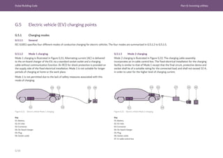
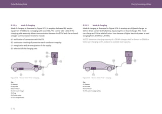
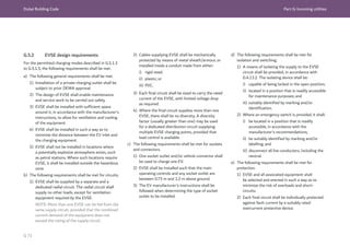
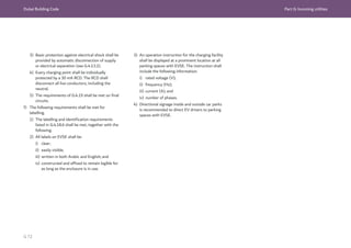
![Dubai Building Code Part G: Incoming utilities
G 73
G.6 Renewable energy
G.6.1 General
As a type of renewable energy, solar energy is clean
and secure. DEWA encourages the use of solar energy
to reduce reliance on traditional energy sources
(such as gas, oil and coal), which are diminishing.
The onsite generation of electricity from a solar PV
shall be by a solar grid-connected system. The grid-
connected solar generator shall be connected to the
DEWA network, and operated and maintained in
accordance with applicable legislation [Ref. G.4] and
DEWA Shams Dubai regulations [Ref. G.5]. System
documentation requirements are described in G.6.2.
NOTE 1: The connection of a solar PV system or
distributed renewable resource generation (DRRG) to
the DEWA grid is subject to DEWA approval.
NOTE 2: Detailed technical requirements are set out in
DEWA Technical publications and resources [Ref. G.6].
The designer shall comply with DEWA specifications,
acceptable standards, procedures and other
requirements published on DEWA website
(Shams Dubai section). The requirements are updated
regularly and form an integral part of the DBC.
Solar power generation systems shall conform to
Section 2, Ch. 14 of the UAE FLSC [Ref. G.1] and
this section.
Building attached photovoltaics (BAPV) systems
attached to roofs, excluding curved or special roofs,
are permitted to achieve a minimum fire classification
of Class C when tested as per the test standards in
Section 2.2.4, Ch. 14 of the UAE FLSC [Ref. G.1].
The minimum fire classification permitted for building
integrated photovoltaics (BIPV) and BAPV systems
other than the above shall be confirmed with DEWA
and DCD upon commencement of design.
G.6.2 System documentation requirements
Consultants and Contractors registered with DEWA
for activities related to grid-connected solar PV
systems (DRRG Solar PV Consultants and DRRG
Solar PV Contractors) shall follow the DEWA
guidelines published on the DEWA website for these
requirements. Applications for solar connections shall
be submitted online and shall include the following
documents:
a) basic system information;
b) details of the system designer;
c) details of the system installer, operation and
maintenance procedure.
NOTE: Detailed requirements are set out in DEWA
Connection guidelines for distributed renewable
resources generators connected to the distribution
network [Ref. G.7].
G.6.3 Wiring diagram datasheets
An annotated/table form single line wiring diagram
that meets the requirements of DEWA Shams Dubai
regulations [Ref. G.5] shall be uploaded with the
DEWA application. It shall include the following
information:
a) PV array general specifications:
1) PV module type(s);
2) total number of PV modules;
3) number of PV strings;
4) PV modules per string;
b) PV string information:
1) string cable specifications – size and type;
2) string fuse specifications (where fitted) – type
and voltage/current ratings;
c) PV array electrical details:
1) PV array main cable specifications, AC and
DC – size and type;
2) PV array junction box locations (where
applicable);
3) DC isolator type, location and rating
(voltage/current);
d) earthing and overvoltage protection:
1) details of all earth/bonding conductors – size
and connection points (to include details of PV
array frame equipotential bonding cable where
fitted);](https://image.slidesharecdn.com/dubaibuildingcodeenglish2021editionak-231227052107-72adb61a/85/Dubai-Building-Code_English_2021-Edition_AK-pdf-475-320.jpg)
![Dubai Building Code Part G: Incoming utilities
G 74
2) Design verification and details of any
connections to an existing lightning protection
system or supplementary lightning protection
system that is to be provided;
3) details of any surge protection device installed
(on both AC and DC lines), including location,
type and rating;
e) AC electrical details, inbuilt and external
protections:
1) AC isolator location, type and rating;
2) AC overcurrent protective device location, type
and rating;
3) residual current device location, type and rating.
G.6.4 Labelling and identification
A solar PV installation shall meet the requirements of
DEWA Shams Dubai regulations [Ref. G.5], together
with the following requirements.
a) All circuits, protective devices, switches and
terminals shall be labelled to identify all relevant
parts of the installation.
b) All DC junction boxes (PV generator and PV
array boxes) shall be provided with caution labels
indicating the risk due to dual source.
c) The main AC isolating switch shall be clearly
labelled.
d) A single line wiring diagram shall be displayed
within the respective electrical rooms/panels.
e) Inverter protection settings and installation details,
as applicable, shall be displayed.
f) The procedures for emergency shutdown shall be
displayed.
g) All signs and labels shall be suitably affixed.
h) Durable copies of all test and commissioning data
shall be provided to the consumer.
G.6.5 Metering and metering provision
DEWA requires access to meter cabinets for the
installation of smart meters (PV generation check
meters and tariff meters). Contractors shall install
meter cabinets in an easily accessible location, in
accordance with G.4.5.](https://image.slidesharecdn.com/dubaibuildingcodeenglish2021editionak-231227052107-72adb61a/85/Dubai-Building-Code_English_2021-Edition_AK-pdf-476-320.jpg)
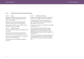
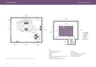
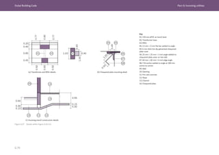
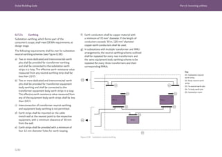
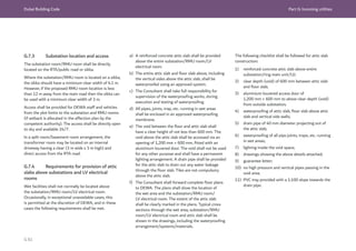
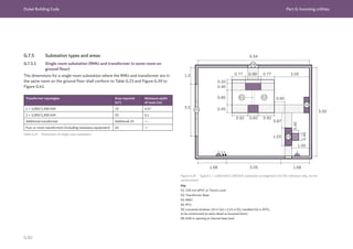
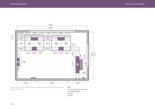
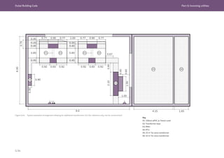
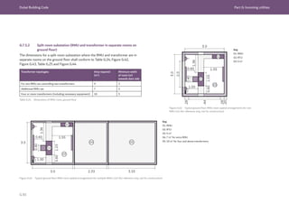

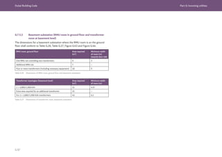
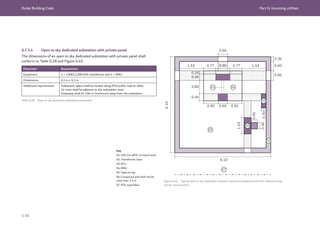
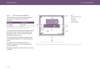
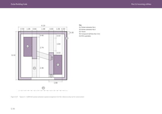
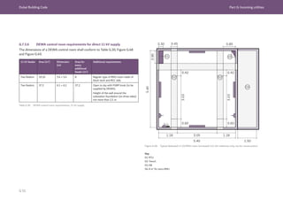
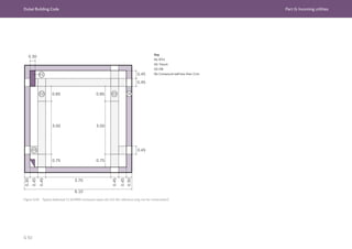
![Dubai Building Code Part G: Incoming utilities
G 93
G.7.6 Substation ventilation and fire
safety provisions
G.7.6.1 General
Substations shall have adequate ventilation
using natural louvers, mechanical ventilation or a
combination of both, depending upon how many sides
of the transformer room have direct access to an
exterior wall.
Substations shall be 2 h fire rated to conform to Table
1.9, Ch. 1 of UAE FLSC [Ref. G.1]. Exterior walls do not
need to be fire rated unless there is a risk of exterior
fire spread and the wall is fire rated in accordance with
Ch. 1 of UAE FLSC [Ref. G.1].
G.7.6.2 Natural ventilation via two exterior walls
Substations at ground floor shall be naturally
ventilated. A minimum of two sides shall be ventilated
using aluminium louvered doors and fixed aluminium
louvers.
Fixed aluminium louver window(s) should be at
600 mm above the outside ground level.
Aluminium louvered doors shall be of the following
sizes:
a) transformer rooms: 3.05 m wide × 2.75 m high;
b) RMU rooms: 2.4 m or 3.05 m wide × 2.75 m high.
NOTE: Door details are shown in Figure G.50 and
Figure G.51.
Substations shall be 2 h fire rated to conform to Table
1.9, Ch. 1 of UAE FLSC [Ref. G.1]. Exterior walls do not
need to be fire rated unless there is a risk of exterior
fire spread and the wall is fire rated in accordance with
Ch. 1 of UAE FLSC [Ref. G.1].
At least one exit door with door swing in the direction
of egress shall be provided. If the door is in a 2 h fire
rated fire rated wall, then the door shall be 90 min fire
rated. Equipment access doors maybe sufficient to
meet this requirement.
Walls enclosing covered parking ramps at the
exit/access of the basement are interior walls. Louvers
shall not be permitted in these walls unless they are
protected in accordance with G.7.6.3.
G.7.6.3 Forced ventilation with no exterior walls
RMU rooms shall be at the ground floor. RMU rooms
shall be 2 h fire rated to conform to Table 1.9, Ch. 1 of
UAE FLSC [Ref. G.1]. Exterior walls do not need to be
fire rated unless there is a risk of exterior fire spread
and the wall is fire rated in accordance with Ch. 1 of
UAE FLSC [Ref. G.1].
Independent mechanical ventilation shall be provided
to transformer rooms with no exterior walls (e.g. in a
basement). All equipment shall be accessed from the
landlord side.
The mechanical ventilation shall be sized to
maintain the ambient temperature in the substation
at maximum of 55 °C based on an outside air
temperature of 48 °C. Supporting calculations shall be
provided to justify the proposed exhaust and supply
rates.
Typical details are shown in Figure G.52.
Louvers shall be provided on two sides of the room as
a back-up to the mechanical ventilation system.
The total grill area shall be not less than 14.9 m2
for
1,000 kVA transformer and not less than 18.6 m2
for
1,500 kVA transformer.
Transformer rooms shall be 2 h fire rated to conform
to Table 1.9, Ch. 1 of UAE FLSC [Ref. G.1].
Louvers shall be protected by automatic 2 h fire rated
shutters or 2 h fire rated curtains on the landlord side
of the louvers (see Figure G.53).
Two combined fire and smoke detectors shall be
provided on the landlord side of the louvers. They
shall be located on the slab soffit within the vicinity
of the louver in accordance with the dimensional
requirements of Table 8.1 (item 25, door release
service), Ch. 8 of UAE FLSC [Ref. G.1].](https://image.slidesharecdn.com/dubaibuildingcodeenglish2021editionak-231227052107-72adb61a/85/Dubai-Building-Code_English_2021-Edition_AK-pdf-495-320.jpg)
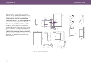
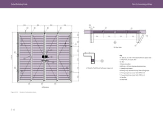
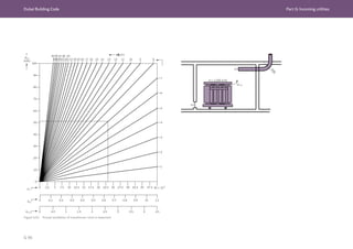
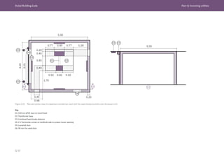
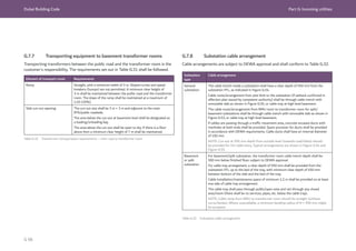
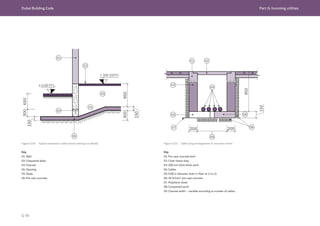
![Dubai Building Code Part G: Incoming utilities
G 101
G.8 Liquefied petroleum gas (LPG)
G.8.1 General
LPG installations shall comply with Ch. 11 of UAE FLSC [Ref. G.1]. LPG main
distribution pipes serving multiple floors of a building shall be contained within a
dedicated 2 h fire rated shaft.](https://image.slidesharecdn.com/dubaibuildingcodeenglish2021editionak-231227052107-72adb61a/85/Dubai-Building-Code_English_2021-Edition_AK-pdf-503-320.jpg)
![Dubai Building Code Part G: Incoming utilities
G 102
G.9 Water
DEWA specification Sample drawing
number
Sample drawing
title
Domestic water
meter installation
in meter room -
guidelines
PEW-STD-
AMI-003
Water meters in
meter room
Bulk meter
installation
in chamber -
guidelines
PEW-STD-
AMI-004
Bulk water meters
in chamber (for bulk
meters 50 mm and
greater diameter
connection)
Bulk meter
installation
in chamber -
guidelines
PEW-STD-
AMI-005
50 mm diameter
bulk water meter
installation in
chamber
(2 in meter with
LDPE connection)
G.9.1 Water metering
A DEWA main meter shall be installed to measure
and record the water demand and consumption of a
building.
Each individual tenancy in a building shall have a sub-
meter installed which is connected to the building main
meter.
Additional requirements for sub-metering are detailed
in H.5.2.6.
Where a building management system or central
control and monitoring system is installed, metering
shall be integrated into the system to allow real time
profiling and management of water demand and
consumption.
G.9.2 Design and installation of water
meters
The design and installation of DEWA water
meters, including smart metering communications
requirements, shall follow the specifications and
sample drawings in the DEWA Circulars and
Regulations [Ref. G.8] and as listed in Table G.33.
Table G.33 DEWA specifications and sample drawings for design and
installation of water meters](https://image.slidesharecdn.com/dubaibuildingcodeenglish2021editionak-231227052107-72adb61a/85/Dubai-Building-Code_English_2021-Edition_AK-pdf-504-320.jpg)
![Dubai Building Code Part G: Incoming utilities
G 103
G.10 District cooling
G.10.1 General
This section identifies the coordination requirements
and common technical requirements related to district
cooling installations and their connection to building
cooling systems.
G.10.2 Coordination with district cooling
Providers
Depending on the location of the development, the
Customer shall contact the relevant district cooling
Provider to obtain the latest district cooling technical
design guidelines [Ref. G.9].
Coordination shall start in the concept design phase
and continue as necessary in later design stages. The
scope of work shall be agreed as part of the service
agreement between the two parties.
NOTE: district cooling Providers in Dubai include (but
are not limited to) those listed in [Ref. G.9].
The building design parameters shall conform to
the district cooling Provider’s specific technical and
interface requirements [Ref. G.9]. The following
parameters shall be determined as a minimum:
a) cooling capacity requirements;
b) pipe connection size;
c) supply/return chilled water temperature on the
primary and secondary sides;
d) maximum allowable system pressure; and
e) design water velocities/pressure drop.
G.10.3 Common technical requirements
The following common technical requirements shall be
met for all developments featuring district cooling.
NOTE 1: The list is provided to assist Customers but
does not replace requirements from the district cooling
Providers.
a) The energy transfer station (ETS) shall
accommodate the district cooling Provider’s heat
exchangers (HEXs), and all associated equipment
for the primary and secondary sides of the HEXs.
The chilled water system configuration shall be
determined by the Customer and coordinated with
the district cooling Provider.
NOTE 2: Figure G.56 and Figure G.57 show
examples of installed ETS pipework and pumps.
b) The secondary side shall include all equipment
for supplying chilled water to the premises.
The pipework installation shall conform to the
requirements identified in H.4.13.
c) The location, configuration and space dimension
for the ETS and valve chamber (VC) shall be agreed
taking into account the route and availability of the
main district cooling pipes. Space planning for the
ETS, including accessibility of the ETS plant, shall
be included in the design at the concept design
phase.
d) The structural Engineer shall design the supporting
structure to withstand the loading imposed by
equipment in the ETS and along the equipment
access route.
e) The ETS shall be provided with electric power,
lighting, communication, potable water, drainage,
ventilation and cooling in accordance with Part G
and Part H.
f) The district cooling facility, including but not limited
to the ETS, cooling towers and other mechanical
and electrical plant rooms, shall conform to the fire
safety requirements of Ch. 14 of the
UAE FLSC [Ref. G.1].
g) In accordance with the service agreement, the
district cooling Provider or Customer shall provide
heat exchanger (HEXs) and primary side chilled
water installation (including all piping from the
underground) to the VC, and to and inside the ETS.
h) The district cooling Provider shall design the VC in
coordination with relevant authorities and based
on the premises load demand. VC civil construction
shall be carried out by the Customer or district
cooling Provider in accordance with the service
agreement.
i) A smart energy metering system shall be provided
in accordance with H.4.14 as part of the primary
chiller water system.
j) The Customer shall provide the secondary side
chilled water piping systems pumps, cooling coils,
and control valves and electrical equipment.
k) The secondary chilled water circuit design shall
align with the supply stated by the district
cooling Provider, and shall return chilled water
temperatures.](https://image.slidesharecdn.com/dubaibuildingcodeenglish2021editionak-231227052107-72adb61a/85/Dubai-Building-Code_English_2021-Edition_AK-pdf-505-320.jpg)
![Dubai Building Code Part G: Incoming utilities
G 106
G.11 Telecommunications
G.11.1 Design and installation of
telecommunications infrastructure
G.11.1.1 General requirements
This section provides the requirements for the design
of all telecommunications (telecom) infrastructure
installations within any development including new
build, “greenfield”, redevelopment, “brownfield”, and
additions, alterations, renovations or refurbishments to
existing buildings, in Dubai.
These requirements are based on version two of the
Telecommunication Regulatory Authority (TRA), In-
Building Telecommunication Network – Specification
Manual Guidelines for FTTx in new
Buildings [Ref. G.10]. If the TRA is updated to give
more stringent requirements, these shall be used in
preference to the DBC.
This section specifies the minimum requirements
to provide a baseline infrastructure. There is no
restriction to extending the baseline, provided that
the design meets the requirements in this section and
does not prevent competition, e.g. by using proprietary
standards.
All telecom infrastructure shall enable each user/
tenant freedom of choice between telecommunication
service providers (SPs).
The requirements cover all of the following aspects of
infrastructure:
a) civil infrastructure and entry ducts;
b) fibre concentration point (FCP) space(s) per
development or plot;
c) meet-me-room (MMR) space(s) per development
or plot;
d) telecom rooms;
e) indoor mobile service and rooftop rooms;
f) building pathways;
g) OSP cables;
h) ISP cables.
Passive optical fibre infrastructure shall be provided to
support deployment of FTTx.
Copper access networks shall not be used for SP
services.
All buildings shall be equipped with physical
infrastructure capable of supporting multiple high-
speed SP networks which can be easily accessed by
the SP. The Developer shall assume a minimum of
two active SPs in the region, but may future-proof the
infrastructure by incorporating provision to support a
possible third SP.
New installations shall be based upon a minimum of
category 6 balanced twisted pair cabling as specified in
ISO 11801 1. Designers may future-proof designs by
providing category 6 A cabling, which supports higher
data rates and provides support for newer power-
over-ethernet (PoE) standards that are typically used
for video surveillance camera and wireless local area
network access points. Where category 6 A is specified,
unshielded twisted pair (UTP) or shielded twisted pair
(STP) may be utilized.
Category 6 cabling (structured cabling system) shall as
a minimum conform to the requirements specified in
G.11.4.10.7.
Cabling within the tenant space (e.g. multi-tenanted
commercial/retail building, home, unit, flat, apartment,
single family home or similar) for onward distribution
of services beyond the tenant equipment is not in the
scope of these requirements.
The requirements of this section do not replace
a detailed specification, act as instruction for
untrained persons, or provide for every specific design
circumstance. For situations beyond the scope of these
requirements, the TRA shall be consulted to obtain
further clarity and guidance.](https://image.slidesharecdn.com/dubaibuildingcodeenglish2021editionak-231227052107-72adb61a/85/Dubai-Building-Code_English_2021-Edition_AK-pdf-508-320.jpg)
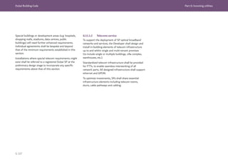
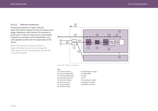
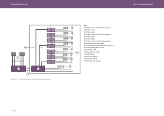
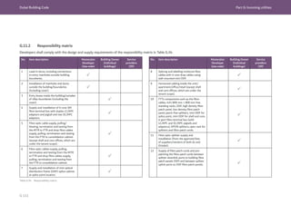
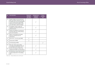
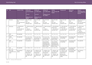
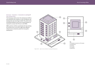
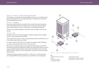
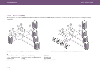
![Dubai Building Code Part G: Incoming utilities
G 118
G.11.4 Inside plant common infrastructure
specifications (ISP)
G.11.4.1 Telecom rooms
G.11.4.1.1 General
The following types of telecom rooms shall be provided
based on the needs of the project.
a) main telecom room (MTR);
b) floor telecom room (FTR);
c) mobile service room (MSR); and
d) rooftop mobile room (RTMR).
In multi-storey buildings, telecom rooms shall be
vertically aligned and linked by a shared cable pathway.
This cable pathway shall not reduce the minimum
required room space.
All telecom rooms shall be for the sole use of SPs. The
rooms shall be accessible to SP personnel 24 hours a
day and be secured from unauthorized entry.
NOTE: It is common for a key to be kept with the
facilities manager.
All telecom rooms shall conform to the fire safety
requirements of UAE FLSC [Ref. G.1]. If the
building Developer has any concerns about access
or the required fire safety provisions, these shall be
highlighted at the design stage.
G.11.4.1.2 Location
Telecom rooms shall be located away from any sources
of:
a) heat;
b) moisture;
c) corrosive atmospheric or environmental conditions;
d) high voltages;
e) radio frequency interference (RFI); and
f) electromagnetic interference (EMI).
Telecom rooms shall not be located directly beneath
or next to wet areas such as showers, washrooms,
swimming pools and waste areas.
G.11.4.1.3 Maintenance
Telecom rooms shall be designed to be free of the
following items unless otherwise indicated in this
section:
a) equipment not associated with the room;
b) utility pipes;
c) cables;
d) sprinkler systems;
e) windows.
Signage shall be added to the room to state “no
storage permitted”.
Rodents often gnaw cables, resulting in damage and
service disruption. Best practice pest control methods
shall be used to prevent pests from entering telecom
spaces and cable pathways.
Additional measures to protect against pests may
involve the installation of covers to cable trays. If used,
covers shall be removable to allow for the installation
of additional cables.
G.11.4.2 Main telecom rooms (MTRs)
The layout and service provision for MTRs shall be in
accordance with Table G.36.
A typical MTR layout is shown in Figure G.64.
MTR frame layouts shall be as detailed in Figure G.65
and Figure G.66.](https://image.slidesharecdn.com/dubaibuildingcodeenglish2021editionak-231227052107-72adb61a/85/Dubai-Building-Code_English_2021-Edition_AK-pdf-520-320.jpg)
![Dubai Building Code Part G: Incoming utilities
G 119
Parameter Details and requirements
MTR (residential
buildings)
MTR (commercial
and mixed use
buildings)
FTR
Purpose Termination of telecom cables and housing
telecom equipment.
The routing, splicing or
termination of telecom cables.
Location Ground or basement floor level.
NOTE: Where single-tenant buildings have
tenant IT server rooms, the MTR should be
located adjacent to this position.
One per floor of multi-tenant
buildings (e.g. commercial or
residential buildings).
Minimum size
and layout
requirements
See Table G.35.
This shall be reviewed based on the building
use and number of tenants and the size
increased accordingly.
Room design shall enable safe and free
access within the MTR. All equipment
cabinets shall be provided with 1 m free
space to the front and rear of every cabinet
position.
Wall-mounted equipment shall be
positioned to provide safe and adequate
working areas for the installation and
maintenance of equipment.
See Table G.35.
Floor loading 10 kN/m2
(distributed load). 10 kN/m2
(distributed load).
Doors Doors shall swing in the direction of egress
with an automatic door closer system fitted
on the hinged edge.
Minimum opening of 1 m × 2.1 m (w × h).
All doors shall be solid wood core or steel
construction with a minimum fire resistance
rating of 90 min.
Two doors shall swing in the
direction of egress with an
automatic door closer fitted on
the hinged edges. At least one
door shall be 810 mm wide in
accordance with Ch. 3 of UAE
FLSC [Ref. G.1]. Total minimum
opening of 1.5 m × 2.1 m (w × h).
All doors shall be solid wood
core or steel construction with a
minimum fire resistance rating of
90 min.
Table G.36 Layout and service requirements for MTRs and FTRs
Parameter Details and requirements
MTR (residential
buildings)
MTR (commercial
and mixed use
buildings)
FTR
Labelling Doors with du and Etisalat telecom room
labels.
Doors with du and Etisalat
telecom room labels.
Penetrations All penetrations and openings to telecom
rooms shall be protected or fire-stopped in
accordance with Section 2 and Section 3, Ch.
1 of UAE FLSC [Ref. G.1].
All ducts directly entering a telecom room
shall be water-sealed and gas-sealed.
All penetrations and openings to
telecom rooms shall be protected
or fire-stopped in accordance
with Section 2 and Section 3, Ch.
1 of UAE FLSC [Ref. G.1].
All ducts directly entering a
telecom room shall be water-
sealed and gas-sealed.
Access
requirement
In order to move equipment into and out of
telecom rooms, access routes and doorways
from outside the building to these rooms
shall be greater than 1 m × 2.1 m (w × h).
Not applicable.
Wall and floor
finish
Rooms shall be free of contaminants and
pollutants.
All walls, floors and ceilings shall be finished
in such a way as to minimize dust and static
electricity.
Surfaces shall be painted with primer and a
light-coloured finish coat.
Rooms shall be free of
contaminants and pollutants.
All walls, floors and ceilings
shall be finished in such a way
as to minimize dust and static
electricity.
Surfaces shall be painted with
primer and a light-coloured finish
coat.
Compartmentation
and egress
Rooms shall conform to the fire and life
safety requirements of Table 1.9, Ch. 1 and
the applicable sections of Ch. 3 to Ch. 10 of
UAE FLSC [Ref. G.1].
Rooms shall conform to the fire
and life safety requirements
of Table 1.9, Ch. 1 and the
applicable sections of Ch. 3 to Ch.
10 of UAE FLSC [Ref. G.1].
Fire suppression Water sprinklers shall not be used.
Rooms ≥ 10 m2
in gross area shall be
protected with clean agent as required by
Table 9.30, Ch. 9 of UAE FLSC [Ref. G.1].
Water sprinklers shall not be used.
Clean agent suppression systems
are not required in typical FTRs
(see Ch. 9 of UAE FLSC [Ref. G.1])](https://image.slidesharecdn.com/dubaibuildingcodeenglish2021editionak-231227052107-72adb61a/85/Dubai-Building-Code_English_2021-Edition_AK-pdf-521-320.jpg)
![Dubai Building Code Part G: Incoming utilities
G 120
Parameter Details and requirements
MTR (residential
buildings)
MTR (commercial
and mixed use
buildings)
FTR
Fire extinguishers One handheld CO2 cylinder extinguisher
and one handheld multi-purpose powder
extinguisher to be provided inside the room.
One handheld CO2 cylinder
extinguisher and one handheld
multi-purpose powder
extinguisher to be provided inside
the room.
Task lighting Task lighting shall be provided to the front
and rear face of equipment cabinets, with a
minimum of 500 lux maintained at
1,000 mm above finished floor level (FFL).
Task lighting shall be provided
to the front and rear face of
equipment cabinets with a
minimum of 500 lux maintained
at 1,000 mm above FFL.
Emergency lighting To be provided in accordance with Ch. 6 of
UAE FLSC [Ref. G.1].
To be provided in accordance with
Ch. 8 of UAE FLSC [Ref. G.1].
Smoke detectors To be provided in accordance with Ch. 6 of
UAE FLSC [Ref. G.1].
To be provided in accordance with
Ch. 8 of UAE FLSC [Ref. G.1].
General power Four 13 A twin sockets fed from the
essential power supply with a dedicated
20 A circuit breaker.
One 13 A twin socket.
Telecoms power Two ×32 A TP
isolator fed with
dedicated feeder
from essential power
supply (EDB).
Two × 40 A TP
isolator fed with
dedicated feeder
from essential power
supply (EDB).
Not applicable.
Earthing
arrangements
One room earth bar. Two room earth
bars connected to
dedicated earth pits
with resistance less
than 1 Ω.
One room earth bar.
Parameter Details and requirements
MTR (residential
buildings)
MTR (commercial
and mixed use
buildings)
FTR
Cooling design All cooling shall be designed such that
cold air is delivered to the front working
face of the telecom equipment cabinets.
This may be directly from the air handling
unit (AHU) or by ducted supply. Return air
shall be allowed to circulate to the AHUs
naturally. AHUs shall be positioned such
as to maintain efficiency of the system by
avoiding mixing of the return air and cold
air paths.
All cooling shall be designed such
that cold air is delivered to the
front working face of the telecom
equipment cabinets. This may
be directly from the AHU or by
ducted supply. Return air shall
be allowed to circulate to the
AHUs naturally. AHUs shall be
positioned such as to maintain
efficiency of the system by
avoiding mixing of the return air
and cold air paths.
Cooling Air conditioning
unit to maintain
the temperature at
24 °C.
Dedicated air
conditioning system
to maintain the
temperature at
21 °C ± 1 °C and the
relative humidity at
50% ± 10%.
A/C system (ducted
split FCU), duty and
standby units with
interlocking.
A/C power from
essential power
supply (EDB).
Heat dissipation
300 W m2
/3 kW per
rack.
Not applicable.
Table G.36 Layout and service requirements for MTRs and FTRs (continued)](https://image.slidesharecdn.com/dubaibuildingcodeenglish2021editionak-231227052107-72adb61a/85/Dubai-Building-Code_English_2021-Edition_AK-pdf-522-320.jpg)
![Dubai Building Code Part G: Incoming utilities
G 121
Figure G.64 Typical layout for a main telecom room (MTR)
Key
01: Lighting (including emergency lighting per Ch. 6 of UAE FLSC [Ref. G.1]
02: AC clean earth bar
03: OSP fibre cable entry
04: General power 4 × 13 A twin sockets fed from essential power supply
05: Telecom power 2 x 40 A TP above racks from essential power supply
06: AHU (duty and standby)
07: Fire detector(s)
08: 2 × handheld fire extinguishers
09: Building riser
10: 450 mm x 50 mm cable tray at high level
A: SP open rack
B: Building ODF](https://image.slidesharecdn.com/dubaibuildingcodeenglish2021editionak-231227052107-72adb61a/85/Dubai-Building-Code_English_2021-Edition_AK-pdf-523-320.jpg)
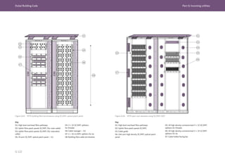
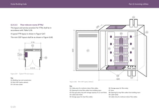
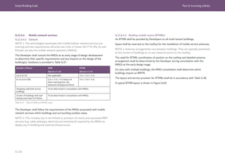
![Dubai Building Code Part G: Incoming utilities
G 125
Parameter Details and requirements
RTMRs MSRs
Purpose Supports the deployment of
installations for area mobile
coverage.
Supports the deployment of
installations for area mobile
coverage.
Location Rooftop In all multi-tenant buildings which
are above G+10 floors, provided on
every 10th floor starting from the
basement/ground floors. Where
possible, located adjacent to the FTR
position
Minimum size and
layout requirements
(w × l × h)
3 m × 3 m × 3 m 3 m × 3 m × 3 m
Floor loading 10 kN/m2
(distributed load). 10 kN/m2
(distributed load).
Doors Door shall swing in the direction of
egress with an automatic door closer
system fitted on the hinged edge.
Minimum opening of 1 m × 2.1 m
(w × h).
All doors shall be solid wood core or
steel construction with a minimum
fire resistance rating of 90 min.
Door shall swing in the direction of
egress with an automatic door closer
system fitted on the hinged edge.
Minimum opening of 1 m × 2.1 m
(w × h).
All doors shall be solid wood core or
steel construction with a minimum
fire resistance rating of 90 min.
Labelling Doors labelled as “Mobile Service
Room”.
Doors labelled as “Mobile Service
Room”.
Penetrations All penetrations and openings to
telecom rooms shall be protected
or fire-stopped in accordance with
Section 2 and Section 3, Ch. 1 of
UAE FLSC [Ref. G.1].
All ducts directly entering a telecom
room shall be water-sealed and gas-
sealed.
All penetrations and openings to
telecom rooms shall be protected
or fire-stopped in accordance with
Section 2 and Section 3, Ch. 1 of
UAE FLSC [Ref. G.1].
All ducts directly entering a telecom
room shall be water-sealed and gas-
sealed.
Table G.38 Layout and service requirements for RTMRs and MSRs
Parameter Details and requirements
RTMRs MSRs
Cable pathways External antenna cable routes.
Openings shall be 600 mm × 400
mm (w × h), 500 mm below the room
ceiling in walls facing the building’s
rooftop area.
Connected to building riser through
300 mm × 50 mm vertical cable tray.
Connected to building riser through
300 mm × 50 mm vertical cable tray.
Wall and floor finish Rooms shall be free of contaminants
and pollutants.
All walls, floors and ceilings shall be
finished in such a way as to minimize
dust and static electricity.
Surfaces shall be painted with primer
and a light-coloured finish coat.
Rooms shall be free of contaminants
and pollutants.
All walls, floors and ceilings shall be
finished in such a way as to minimize
dust and static electricity.
Surfaces shall be painted with primer
and a light-coloured finish coat.
Compartmentation
and egress
Rooms shall conform to the fire and
life safety requirements of Table 1.9,
Ch. 1 and the applicable sections of
Ch. 3 to Ch. 10 of
UAE FLSC [Ref. G.1].
Rooms shall conform to the fire and
life safety requirements of Table 1.9,
Ch. 1 and the applicable sections of
Ch. 3 to Ch. 10 of
UAE FLSC [Ref. G.1].
Fire suppression Water sprinklers shall not be used.
Rooms ≥ 10 m2
in gross area shall
be protected with clean agent as
required by Table 9.30, Ch. 9 of
UAE FLSC [Ref. G.1].
Water sprinklers shall not be used.
Rooms ≥ 10 m2
in gross area shall
be protected with clean agent as
required by Table 9.30, Ch. 9 of
UAE FLSC [Ref. G.1].
Fire extinguishers One handheld CO2 cylinder
extinguisher and one handheld multi-
purpose powder extinguisher to be
provided inside the room.
One handheld CO2 cylinder
extinguisher and one handheld multi-
purpose powder extinguisher to be
provided inside the room.](https://image.slidesharecdn.com/dubaibuildingcodeenglish2021editionak-231227052107-72adb61a/85/Dubai-Building-Code_English_2021-Edition_AK-pdf-527-320.jpg)
![Dubai Building Code Part G: Incoming utilities
G 126
Parameter Details and requirements
RTMRs MSRs
Task lighting Task lighting shall be provided to
the front and rear face of equipment
cabinets with a minimum of 500 lux
maintained at 1,000 mm above FFL.
Task lighting shall be provided to
the front and rear face of equipment
cabinets with a minimum of 500 lux
maintained at 1,000 mm above FFL.
Emergency lighting To be provided in accordance with
Ch. 6 of UAE FLSC [Ref. G.1].
To be provided in accordance with
Ch. 6 of UAE FLSC [Ref. G.1].
Smoke detectors To be provided in accordance with
Ch. 8 of UAE FLSC [Ref. G.1].
To be provided in accordance with
Ch. 8 of UAE FLSC [Ref. G.1].
General power Four 13 A twin sockets fed from
the essential power supply with a
dedicated 20 A circuit breaker.
Four 13 A twin sockets fed from
the essential power supply with
dedicated 20 A circuit breaker.
Telecoms power Two 63 A TP isolators fed with
dedicated feeder from essential
power supply.
Two 63 A TP isolators fed with
dedicated feeder from essential
power supply.
Earthing
arrangements
Two room earth bars connected to
dedicated earth pits with resistance
less than 1 Ω.
Two room earth bars connected to
dedicated earth pits with resistance
less than 1 Ω.
Cooling design All cooling shall be designed such
that cold air is delivered to the
front working face of the telecom
equipment cabinets. This may be
directly from the air handling unit
(AHU) or by ducted supply. Return
air shall be allowed to circulate to
the AHUs naturally. AHUs shall
be positioned such as to maintain
efficiency of the system by avoiding
mixing of the return air and cold air
paths.
All cooling shall be designed such
that cold air is delivered to the
front working face of the telecom
equipment cabinets. This may be
directly from the AHU or by ducted
supply. Return air shall be allowed
to circulate to the AHUs naturally.
AHUs shall be positioned such as to
maintain efficiency of the system by
avoiding mixing of the return air and
cold air paths.
Table G.38 Layout and service requirements for RTMRs and MSRs (continued)
Parameter Details and requirements
RTMRs MSRs
Cooling Dedicated air conditioning system to
maintain the temperature at 21 °C
± 1 °C and the relative humidity at
50% ± 10%.
A/C system (ducted split FCU), duty
and standby units with interlocking.
A/C power from essential power
supply.
Heat dissipation 36 kW.
Dedicated air conditioning system to
maintain the temperature at 21 °C
± 1 °C and the relative humidity at
50% ± 10%.
A/C system (ducted split FCU), duty
and standby units with interlocking.
A/C power from essential power
supply.
Heat dissipation 12 kW.
Key
01: Cross connect cabinet
02: AC clean earth bar
03: DC clean earth bar
04: 32 A twin socket fed from
utility power with dedicated
circuit breaker
05: Smoke detector connected
to BMS
06: 300 mm width cable ladder
at high level
07: 2 × 63 A three-phase isolator
fed from essential building power
08: 2 × handheld extinguishers
09: Opening for containments
Figure G.69 Typical layout for RTMR and MSRs](https://image.slidesharecdn.com/dubaibuildingcodeenglish2021editionak-231227052107-72adb61a/85/Dubai-Building-Code_English_2021-Edition_AK-pdf-528-320.jpg)
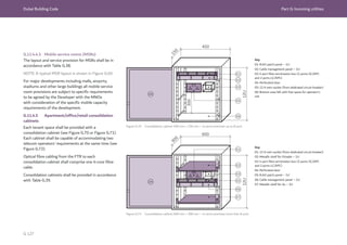
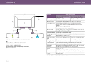
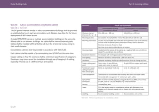
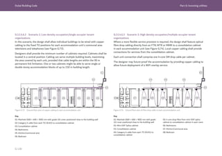
![Dubai Building Code Part G: Incoming utilities
G 132
G.11.4.8 Cable pathways
G.11.4.8.1 General
Cable pathway specifications shall conform to Table
G.42.
The following requirements shall be met for risers and
all cable trays, conduits, ducts and microduct pathway
systems.
a) Pathways shall be designed such that installed
cables do not exceed the minimum specified bend
radius during or after installation.
b) Day one installation shall not exceed 50% of the
cable tray capacity.
c) All cable trays shall be made from hot dip
galvanized slotted steel and shall be of HDRF
construction.
d) All metal parts shall be free from sharp edges and
shall be earth bonded in accordance with ISO/IEC
30129.
e) Riser openings, slab penetrations and wall
penetrations for pathways passing through fire-
rated construction shall be sealed with approved
fire-stopping material in accordance with Section
3, Ch.1 of UAE FLSC [Ref. G.1]. Fire-stopping shall
be reinstated whenever cables are installed after
completion of initial fire-stopping works.
f) Vertical pathways shall be continuous between
all levels. There shall be no reduction of capacity
through penetrations.
g) Pathways shall not run through areas exposed to:
1) excessive heat (i.e. areas in direct sun or rooms
with heat generating equipment);
2) moisture;
3) corrosive atmospheric or environmental
conditions;
4) high voltages;
5) radio frequency interference (RFI); or
6) electromagnetic interference (EMI).
h) The separation of telecom and electrical pathways
shall conform to ISO 14763-2.
i) Cable trays shall be easily accessible in common
areas to facilitate any future provision of additional
cables.
j) Cable trays in publicly accessible areas and
less than 4.8 m above the floor level shall have
removable protective covers.
k) All conduit junctions/pull boxes shall have minimum
internal dimensions of 300 mm × 300 mm × 150
mm (w × h × d).
l) The Developer shall select telecom riser locations
to provide a continuous route through the
building, and taking into account the location
and distribution of other services. On some
developments, multiple risers might be required to
provide service resilience.
m) Risers and cable pathways allocated for SP use
shall not be shared with landlord or tenant cabling
systems. In specific developments where space
optimization might be advantageous, the Developer
shall agree riser sharing principles for FTTx cabling
and bespoke landlord/tenant cabling.
n) Minimum in-building service (IBS) pathways
shall be adapted to accommodate specific design
requirements of MNOs per development.](https://image.slidesharecdn.com/dubaibuildingcodeenglish2021editionak-231227052107-72adb61a/85/Dubai-Building-Code_English_2021-Edition_AK-pdf-534-320.jpg)
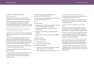
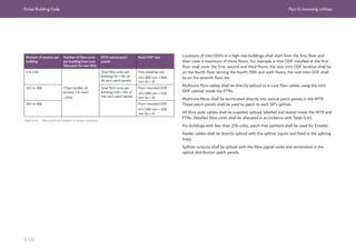
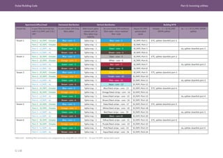
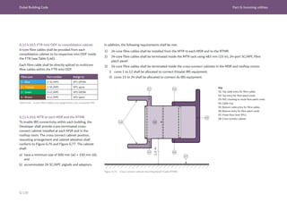
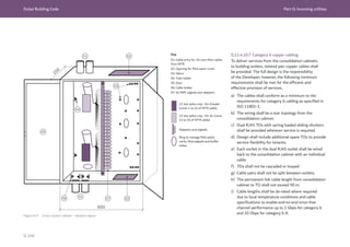
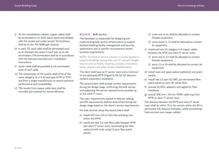
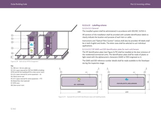
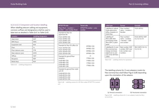
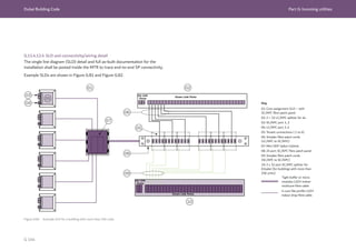

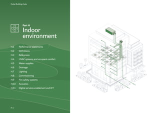
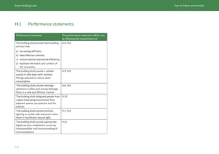
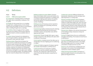
![Dubai Building Code Part H: Indoor environment
H 6
Oil separator: Below-ground vessel used to intercept
contaminated drainage flows that incorporate oil or
petrol.
Rainwater: Water resulting from natural precipitation
that has not been deliberately contaminated.
Rainwater pipe: Pipe used to collect and transport
rainwater from building roof areas to another drainage
system.
Rodding eye: Removable fitting that provides access
into the drainage system for cleaning and maintenance.
Rodding point: Small diameter connection into
the drainage systems that permits entry into the
system for cleaning or inspection of the downstream
connection.
Sanitary fittings: Fixed appliances supplied with water
that are used for cleaning and washing (i.e. baths,
showers, wash basins, bidets, water closets, urinals,
dishwashers and washing machines).
Sanitation pipework: Arrangement of discharge
pipework, with or without ventilated pipes, connected
to a drainage system.
Septic tank: Tank installed below ground in which
sewage is collected and allowed to decompose through
bacterial activity before draining to a soakaway.
Soakaway: Buried drainage feature used to manage
surface water on-site and infiltrate into the
surrounding ground.
Upper floor: Any floor above the lowest level, which
could be a basement level.
Ventilation pipework: Main vertical ventilating pipe,
connected to a discharge stack, to limit pressure
fluctuations within the discharge stack.
Wastewater: Water which is contaminated by use and
all water discharging into the drainage system.
Water trap: Device that the prevents foul air by means
of a water seal.
H.2.1.4 Acoustics
Noise: Unwanted sound.
Reverberation time: Time, measured in seconds (s),
taken for the sound to decay by 60 dB after a sound
source has been stopped.
Reverberation: Persistence of sound in a space after a
sound source has been stopped.
Sound pressure level: Physical intensity of sound,
measured in decibels (dB).
H.2.1.5 Fire safety
Exit: Portion of a means of egress that is separated
from all other spaces of the building or structure by
construction, location or equipment as required to
provide a protected way of travel from exit access to
the exit discharge.
Exit access: Portion of a means of egress that leads to
an exit.
Exit discharge: Portion of a means of egress between
the termination of an exit and a public way.
High-rise building: Building height greater than or
equal to 23 m and up to 90 m, measured in accordance
with the UAE FLSC [Ref. H.1]. A more detailed
definition is given in UAE FLSC.
Super high-rise building: Building height greater than
90 m, measured in accordance with the UAE FLSC
[Ref. H.1]. A more detailed definition is given in
UAE FLSC.
H.2.1.6 Lighting
Electronic ballast: A piece of equipment required
to control the starting and operating voltages of
fluorescent lights. Electronic lighting ballasts use solid
state circuitry and can greatly reduce or eliminate any
flicker in the lamps.
Lighting power density: Electrical power consumed
by the lighting installation per unit floor area (W/m2
)
or unit length, linear metre (W/lm) of an illuminated
space.
Lux: Unit of illuminance, measuring luminous flux per
unit area.](https://image.slidesharecdn.com/dubaibuildingcodeenglish2021editionak-231227052107-72adb61a/85/Dubai-Building-Code_English_2021-Edition_AK-pdf-553-320.jpg)

![Dubai Building Code Part H: Indoor environment
H 14
H.3.1.3 Water supplies
BS EN 806, Specification for installations inside
buildings conveying water for human consumption
BS EN 1825-1, Grease separators. Principles of design,
performance, and testing, marking and quality control
BS EN 8558, Guide to the design, installation, testing
and maintenance of services supplying water for
domestic use within their buildings and their curtilages
BS 5422, Method for specifying thermal insulating
materials for pipes, tanks, vessels, ductwork and
equipment operating within a temperature range
-40 °C to +700 °C
Ref. H.25 HEAL
TH AND SAFETY EXECUTIVE, 2013.
Approved Code of Practice L8 – Legionnaires’ disease
– The control of legionella bacteria in water systems.
London: HSE.
Ref. H.26 HEAL
TH AND SAFETY EXECUTIVE, 2013.
Legionnaires’ disease – Technical guidance – Part 1:
The control of legionella bacteria in evaporative cooling
systems. HSG274 Part 1. London: HSE.
Ref. H.27 HEAL
TH AND SAFETY EXECUTIVE, 2014.
Legionnaires’ disease – Technical guidance – Part 2:
The control of legionella bacteria in hot and cold water
systems. HSG274 Part 2. London: HSE.
Ref. H.28 HEAL
TH AND SAFETY EXECUTIVE, 2013.
Legionnaires’ disease – Technical guidance – Part 3:
The control of legionella bacteria in other risk systems.
HSG274 Part 3. London: HSE.
Ref. H.29 HEAL
TH AND SAFETY EXECUTIVE, 2017.
Control of legionella and other infectious agents in
spa-pool systems. HSG272. London: HSE.
Ref. H.30 HEAL
TH AND SAFETY EXECUTIVE, 2014.
Health and safety in care homes. HSG220. London:
HSE.
Ref. H.31 GREAT BRITAIN. Water Industry Act 1999.
The Water Supply (Water Fittings) Regulations.
London: The Stationery Office.
Ref. H.32 DUBAI ELECTRICITY AND WATER
AUTHORITY (DEWA). Circulars and Regulations
[online database]. Available from: www.dewa.gov.ae/
en/builder/useful-tools/dewa-circulars.
Ref. H.33 DUBAI MUNICIPALITY HEAL
TH AND
SAFETY DEPARTMENT, 2010 (undergoing revision).
Guidelines for the control of Legionella in water
systems. Dubai: Dubai Municipality.
Ref. H.34 DUBAI MUNICIPALITY HEAL
TH AND
SAFETY DEPARTMENT, 2020. Private swimming pools
safety guidelines. DM-PH&SD-GU80-PRSPS2. Dubai:
Dubai Municipality.
Ref. H.35 DUBAI MUNICIPALITY HEAL
TH AND
SAFETY DEPARTMENT, 2019. Public swimming pools
safety guidelines. DM-PH&SD-GU81-PSPS2. Dubai:
Dubai Municipality.
Ref. H.36 DUBAI ELECTRICITY AND WATER
AUTHORITY (DEWA). 2020. Water transmission
planning guidelines for development projects. Dubai:
Water Transmission Planning Department.
H.3.1.4 Drainage
BS EN 124-1, Gully tops and manhole tops for
vehicular and pedestrian areas – Definitions,
classification, general principles of design, performance
requirements and test methods
BS EN 752, Drain and sewer systems outside buildings
BS EN 1329-1, Plastic piping systems for soil and
waste discharge (low and high temperature) within the
building structure – Unplasticized poly(vinyl chloride)
(PVC-U) – Specification for pipes and fittings
BS EN 1610, Construction and testing of drains and
sewers
BS EN 8588, Separator systems for light liquids (oil
and petrol) – Principles of product design, performance
testing, marking and control
BS EN 12056, Gravity drainage systems inside
buildings](https://image.slidesharecdn.com/dubaibuildingcodeenglish2021editionak-231227052107-72adb61a/85/Dubai-Building-Code_English_2021-Edition_AK-pdf-561-320.jpg)
![Dubai Building Code Part H: Indoor environment
H 16
ISO 19650, Organization and digitization of
information about buildings and civil engineering
works, including building information modelling
(BIM) — Information management using building
information modelling.
ISO 29481-1, Building information models –
Information delivery manual – Part 1: Methodology
and format
ISO/IEC 11801-1, Information technology – Generic
cabling for customer premises – Part 1: General
requirements
ISO/IEC 11801-2, Information technology – Generic
cabling for customer premises – Part 2: Office
premises
ISO/IEC 11801-3, Information technology – Generic
cabling for customer premises – Part 3: Industrial
premises
ISO/IEC 11801-4, Information technology – Generic
cabling for customer premises – Part 4: Single-tenant
homes
ISO/IEC 11801-5, Information technology – Generic
cabling for customer premises – Part 5: Data centres
ISO/IEC 11801-6, Information technology – Generic
cabling for customer premises – Part 6: Distributed
building services
ISO/IEC 14763-1, Information technology –
Implementation and operation of customer premises
cabling – Part 1: Administration
ISO/IEC 14763-2, Information technology –
Implementation and operation of customer premises
cabling – Part 2: Planning and installation
ISO/IEC 14763-3, Information technology –
Implementation and operation of customer premises
cabling – Part 3: Testing of optical fibre cabling
ISO/IEC 30129, Information technology –
Telecommunications bonding networks for buildings
and other structures
ISO/IEC 30141, Internet of Things (IoT) – Reference
architecture.
ISO/IEC 61158, Industrial communication networks
– Fieldbus specifications – Part 1: Overview and
guidance for the IEC 61158 and IEC 61784 series
Ref. H.51 TELECOMMUNICATIONS REGULATORY
AUTHORITY, 2018. Internet of Things (IoT) Regulatory
Policy v1.0. Telecommunications. UAE: TRA.
Ref. H.52 TELECOMMUNICATIONS REGULATORY
AUTHORITY, 2019. Internet of Things (IoT) Regulatory
Procedure v1.0. UAE: TRA.
Ref. H.53 BUILDING DEVICE NAMING STANDARD
(BDNS). Available from: github.com/theodi/BDNS
[viewed: 08 September 2020].
Ref. H.54 TELECOMMUNICATIONS REGULATORY
AUTHORITY, 2009. Use of 2.4 GHz and 5.8 GHz bands
for Wireless Local Area Network (WLAN) and radio
local area network (RLAN) v1.0. UAE: TRA.
Ref. H.55 TELECOMMUNICATIONS REGULATORY
AUTHORITY, 2016. Regulations for fixed radio
systems, v2.0. UAE: TRA.
Ref. H.56 TELECOMMUNICATIONS REGULATORY
AUTHORITY, 2019. TS HS 001 – Technical
specification – Requirements for health and safety.
UAE: TRA.
Ref. H.57 INTERNATIONAL COMMISSION ON
NON-IONIZING RADIATION PROTECTION, 2020.
Guidelines for limiting exposure to electromagnetic
fields (100 KHz to 300 GHz). Oberschleissheim:
ICNIRP.](https://image.slidesharecdn.com/dubaibuildingcodeenglish2021editionak-231227052107-72adb61a/85/Dubai-Building-Code_English_2021-Edition_AK-pdf-563-320.jpg)
![Dubai Building Code Part H: Indoor environment
H 17
H.3.2 Further reading
H.3.2.1 Water supplies and drainage
BS EN 12201, Polyethylene (PE) pipes for water
supply, and for drainage and sewerage under pressure
– Dimensions
BS 6700, Design, installation, testing and maintenance
of service supplying water for domestic use within
buildings and their curtilages – Specification
CHARTED INSTITUTION OF BUILDING SERVICES
ENGINEERS, 2014. Guide G – Public health and
plumbing engineering guide. London: CIBSE.
CHARTERED INSTITUTE OF PLUMBING AND
HEATING ENGINEERING, 2002. Plumbing engineering
services design guide. Essex: CIPHE.
H.3.2.2 Acoustics
INSTITUTE OF ACOUSTICS AND ASSOCIATION OF
NOISE CONSUL
TANTS, 2014. Acoustics of Schools: A
design guide. London: IOA and ANC.
H.3.2.3 Digital services enablement and ICT
BICSI, 2020. Telecommunications distribution methods
manual (TDMM), 14th edition. Florida: BICSI.
ANSI/BICSI 007-2020, Information communication
technology design and implementation practices for
intelligent buildings and premises. Florida: BICSI.
ANSI/BICSI 003-2018, Building information modelling
(BIM). Florida: BICSI.
BICSI, 2018. Information technology systems.
Installation methods manual, 7th edition. Florida:
BICSI.
BICSI, 2018. Essential of bonding and grounding, 1st
edition. Florida: BICSI.
Brick Schema. Available from <brickschema.org/>
[viewed 8 September 2020].](https://image.slidesharecdn.com/dubaibuildingcodeenglish2021editionak-231227052107-72adb61a/85/Dubai-Building-Code_English_2021-Edition_AK-pdf-564-320.jpg)
![Dubai Building Code Part H: Indoor environment
H 18
H.4 HVAC systems and occupant comfort
H.4.1 General
This section sets out the minimum requirements and basis of design for heating,
ventilation and air-conditioning (HVAC) systems and thermal comfort within
buildings. Relevant sustainability criteria and cross-references to
UAE FLSC [Ref. H.1] are included.
HVAC systems shall be designed to minimize energy usage and ensure the comfort of
building occupants. Systems shall be selected to ensure long life, easy maintenance,
and simple and effective controls.
For systems or applications not covered by this section, design solutions and
guidance shall be obtained from the current edition of the ASHRAE handbooks,
guides and standards.
The requirements for healthcare buildings, and all relevant codes and standards, are
identified within the Dubai Health Authority (DHA) Regulations
[Ref. H.2 to Ref. H.11] and DHA Health facility guidelines [Ref. H.12 to Ref. H.16].
H.4.2 Protection of structure
The building or structure shall not be weakened by the installation of mechanical
systems.
Mechanical equipment to be supported by the structure and any associated seismic
bracing shall be coordinated with the Structural Engineer. Installation of mechanical
systems over structural joints should be avoided. If that is not possible, flexible
ducts/pipes may be used.
Where any portion of the building or structure needs to be altered or replaced in the
process of installing or repairing any mechanical system, the building or structure
shall be left in a safe structural condition in accordance with Part F.
Penetrations of floor/ceiling assemblies, and any assemblies that are required to have
a fire-resistance rating, shall be protected in accordance with Section 3, Ch. 1 of UAE
FLSC [Ref. H.1].
H.4.3 Equipment and appliance location
HVAC equipment and appliances shall not be installed in a hazardous location unless
listed and approved for the specific installation.
Fuel-fired appliances shall not be in, or obtain combustion air from, any of the
following rooms or spaces:
a) sleeping rooms;
b) bathrooms;
c) toilet rooms;
d) storage closets;
e) surgical rooms.
This subsection does not apply to direct-vent appliances that obtain all combustion
air directly from the outdoors.
Appliances shall not be installed where they might be subject to mechanical damage
unless protected by approved barriers.
Appliances installed in outdoor locations shall be approved by the Authority for
outdoor installation.
Mechanical equipment and systems shall not be installed in an elevator shaft.
Individual heat rejection equipment having a power rating greater than 4.0 kW, and
which exhausts externally, shall be installed not less than 3 m above the external
ground level of the building.
To reduce damage to property from leaks, fan coil units shall be installed in wet areas
in residential apartment buildings.](https://image.slidesharecdn.com/dubaibuildingcodeenglish2021editionak-231227052107-72adb61a/85/Dubai-Building-Code_English_2021-Edition_AK-pdf-565-320.jpg)
![Dubai Building Code Part H: Indoor environment
H 19
H.4.4 Access and service space
HVAC equipment and appliances shall be accessible for inspection, service, repair and
replacement. Access shall not necessitate disabling the function of a fire-resistance-
rated assembly, or removing any of the following:
a) permanent construction;
b) other appliances; and
c) venting systems or other piping or ducts not connected to the appliance being
inspected, serviced, repaired or replaced.
The requirements given in ASHRAE 180 shall be met for HVAC systems.
A level working space at least 762 mm × 762 mm shall be provided in front of the
control side to service an appliance. Rooms containing appliances shall be provided
with a door and an unobstructed access path measuring not less than
915 mm wide × 2.3 m high. Where equipment and appliances requiring access are
installed on roofs or elevated structures at a height exceeding 4,800 mm, such access
shall be provided by a permanent approved means of access.
H.4.5 Acoustic requirements and noise criteria
Ch. 49, Table 1 of the ASHRAE HVAC applications handbook [Ref. H.17] identifies
design guidelines for acceptable noise levels for HVAC-related background noise
for a range of typical building and room types. These design guidelines shall be
used as the basis for determining acceptable noise levels for the specific occupancy.
If a higher or lower value is considered desirable, an analysis of economics, space
use and user needs shall be obtained from an Acoustic Consultant to determine an
appropriate value.
An experienced Acoustic Consultant shall be engaged to provide guidance on
acoustically critical spaces such as (but not limited to) audio control rooms,
broadcasting studios, places of worship, lecture theatres, cinemas, shopping malls,
gymnasium located over habitable spaces, school auditoria and for all performing arts
spaces.
NOTE: Further details are given in H.10.](https://image.slidesharecdn.com/dubaibuildingcodeenglish2021editionak-231227052107-72adb61a/85/Dubai-Building-Code_English_2021-Edition_AK-pdf-566-320.jpg)
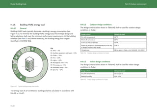
![Dubai Building Code Part H: Indoor environment
H 21
Indoor design conditions might vary depending on the occupancy or use of the
building. The ASHRAE HVAC applications handbook [Ref. H.17] shall be used as the
reference for all indoor design conditions for specific occupancies or usage.
When diversity factors to be used in heat load calculations are not known, the
coefficients indicated in ASHRAE Fundamentals handbook [Ref. H.18], Ch. 18 shall
be used.
The following safety factors shall be applied:
a) sensible heat: ≤10%;
b) latent heat: ≤5%.
H.4.6.4 Outdoor air design conditions
All buildings that are fully air-conditioned shall be provided with an outdoor air
system. The system shall ensure that the building is provided with treated outdoor
air for at least 95% of the year. The following maximum design temperatures shall be
used:
a) dry bulb temperature: 34 °C;
b) wet bulb temperature: 32 °C.
H.4.6.5 Heat gain and loss calculations
Heat load calculations shall be carried out for each air-conditioned space, including
peak load incidence in that space. The calculations shall be carried out using software
registered with the Authority.
H.4.6.6 External load criteria
The building envelope shall meet the requirements in Part E to determine thermal
transmittance and shading coefficients.
The following parameters shall be taken into account in the building load calculations:
a) building envelope orientation;
b) building envelope design and construction details;
c) building floor plans;
d) building elevations and sections;
e) impact of external shading factors (see E.5.3); and
f) any special requirements for the building use or operation.
H.4.6.7 Internal load criteria
H.4.6.7.1 Occupancy
The total number of occupants within the building shall be determined based on
room occupancy data provided by the client or Architect. Occupant loads shall be
determined in accordance with B.5.1.
Where occupancy density for each space is not identified, the default occupancy
density values stated in ASHRAE 62.1, ASHRAE 62.2 and ASHRAE 170 shall be
used.
H.4.6.7.2 Lighting
Project-specific lighting loads shall be used. Where lighting loads are not available,
they shall be determined based on the recommendations in ASHRAE 90.1.
H.4.6.7.3 Electrical equipment loads
Project specific electrical equipment loads shall be used. Where equipment loads are
not available, they shall be as recommended in ASHRAE 90.1 for each application
type.](https://image.slidesharecdn.com/dubaibuildingcodeenglish2021editionak-231227052107-72adb61a/85/Dubai-Building-Code_English_2021-Edition_AK-pdf-568-320.jpg)
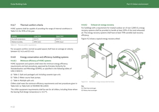
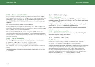
![Dubai Building Code Part H: Indoor environment
H 24
H.4.10.2 Minimum ventilation requirements for adequate indoor air quality
All air-conditioned buildings shall be ventilated either mechanically or by mixed mode.
They shall meet the minimum requirements of ASHRAE 62.1, ASHRAE 62.2 and
ASHRAE 170.
Occupancy density shall be determined in accordance with B.5.1 where possible.
If the occupancy is not listed in B.5.1, the outdoor air flow rate shall be based
on the default occupancy density values stated in ASHRAE 62.1, ASHRAE 62.2
and ASHRAE 170.
H.4.10.3 Indoor air quality
Air filters for general ventilation shall meet the efficiency classification given
in ISO 16890-1 based upon particulate matter.
The maximum limit for the indoor air contaminants stated in Table H.4 shall
not be exceeded.
Indoor air quality testing shall be carried out prior to occupancy. A test report
showing compliance with these requirements shall be submitted to the Authority.
Contaminant Maximum limit Sampling duration
Formaldehyde <0.08 (ppm)
Total volatile organic compound
(TVOC)
<300 μg/m³ 8 h continuous monitoring (8 h
time-weighted average [TWA])
Suspended Particulates
(<10 μm)
<150 μg/m³
Table H.4 Schedule, duration of sampling and maximum limit for contaminants
Air quality testing shall be carried out by specialized companies or laboratories
accredited by the Authority.
Air quality testing equipment shall have an initial and periodical calibration certificate
as specified in ISO/IEC 17025. Calibration certification shall be carried out either
annually or as specified by the manufacturer, whichever is the more frequent,
and shall be carried out by an external calibration facility, accredited by the Authority.
The initial and periodical calibration certificates shall be saved in a dedicated register.
The calibration certificate shall be checked by the Authority to validate the accuracy
of the readings. Calibration certificates shall also be provided when renewing
the indoor air quality certificate of the building.
Paints, coatings, adhesives and sealants used in the building shall not exceed
the allowed limits for volatile organic compound (VOC) specified by the Dubai
Central Laboratory [Ref. H.19]. These materials shall be accredited/certified from
Dubai Central Laboratory, or any other laboratory approved by the Authority.
Carpet systems (carpets or new permanently installed carpet padding) shall
be certified/accredited by the Dubai Central Laboratory, or any other laboratory
approved by the Authority. Carpets shall not be installed in labour accommodation,
educational facilities or any other places as determined by the Authority.
NOTE: Alternative filtration techniques, such as electronic filters and air cleaners
using photocatalytic oxidation, should be approved by the Authority prior to
installation/use due to negative health effects that can arise from exposure to ozone
and its volatile reaction products. Substantial technical evidence is required on the
use of these techniques and should be validated by international agencies and test
standards. They are not considered to be a replacement for mechanical filtration,
but can be used as aids to achieve better indoor air quality.](https://image.slidesharecdn.com/dubaibuildingcodeenglish2021editionak-231227052107-72adb61a/85/Dubai-Building-Code_English_2021-Edition_AK-pdf-571-320.jpg)
![Dubai Building Code Part H: Indoor environment
H 25
H.4.10.4 Air inlets and exhausts
Outdoor air inlets for all ventilation systems, including doors, operable windows and
mixed mode ventilation systems, shall be located at a suitable distance from potential
sources of contamination as specified in ASHRAE 62.1, ASHRAE 62.2 and the
ASHRAE HVAC applications handbook [Ref. H.17].
NOTE: This is to reduce the possibility of odour, smoke or other air contaminants
entering the ventilation system.
Exhaust air shall be discharged in such a way that it does not get drawn back into the
building or the building ventilation system. It also shall not become a nuisance to the
building occupants or occupants of nearby buildings or to pedestrians.
Air inlets and exhaust louvers/vents shall be positioned such as to prevent
recirculation of air, and separated by a distance not less than the minimum given in
Table 5-1 of ASHRAE 62.1:2019. Air inlets and exhausts shall be located relative to
prevailing wind directions, using wind rose diagrams for the building. Air inlets shall
be positioned at upwind or windward direction. Exhausts (such as from kitchens,
toilets and smoke extract) shall discharge at downwind or leeward direction.
Intake air shall be drawn into the system through sand trap louvers sized for at
least 1 m/s across the face area of the louver, to provide an 80% or higher filtration
efficiency at coarse sand grain size (355 μm to 425 μm).
H.4.10.5 Isolation of pollutant sources
All buildings with activities producing hazardous fumes or chemicals (such as print
rooms and laboratories) shall be provided with dedicated air extraction systems for
those spaces. The system shall create negative pressure and exhaust the fumes or
chemicals, to prevent them from entering adjacent rooms.
H.4.10.6 Pandemic air quality measures
The recent pandemic has meant that many Owners and tenants are looking to
enhance ventilation solutions to improve air quality and to control airborne diseases
and pollutants. The research and technologies in this field are evolving and later
editions of the DBC might include specific design requirements. In the interim,
Owners wishing to add filtration and purification systems to control airborne
infectious diseases in epidemic/pandemic situations, or to control bacterial pollutants
in the air, shall consult the Authorized Department in DM for advice and approval of
the proposed technology.
H.4.11 Natural ventilation
Natural ventilation of occupied spaces via windows, doors or other openings is
permitted but shall not be relied upon to provide ventilation and thermal comfort.
Operating mechanisms for such openings shall be accessible so that the openings are
readily operable by the building occupants.](https://image.slidesharecdn.com/dubaibuildingcodeenglish2021editionak-231227052107-72adb61a/85/Dubai-Building-Code_English_2021-Edition_AK-pdf-572-320.jpg)
![Dubai Building Code Part H: Indoor environment
H 26
H.4.12 Mechanical ventilation
H.4.12.1 General
The ventilation system design and selection shall be determined by the mechanical
design Engineer for the given application, taking into account all relevant issues
associated with the building design, usage, configuration and commissioning,
operation and maintenance of the system.
Mechanical ventilation shall be provided by a method of supply air and return or
exhaust air (see Figure H.3). The amount of supply air shall be approximately equal
to the amount of return and exhaust air. The system shall not be prohibited from
producing negative or positive pressure. Air handling units shall deliver filtered and
conditioned air within the building. Air handling units shall be American Heating and
Refrigeration Institute or Eurovent certified.
Mechanical ventilation installations shall meet the requirements given in Ch. 16 of
the ASHRAE Fundamentals handbook [Ref. H.18].
Figure H.3 Example of a mechanical balanced ventilation for non-residential buildings (© Crown Copyright,
1998. Modified figure based on Figure 1, Good practice guide 257, The Department of the Environment,
Transport and the Regions (DETR). Contains public sector information licensed under the Open Government
Licence v3.0)
Key
01: Exhaust air outlet
02: Exhaust air louver
03: Shut-off damper
04: Heat recovery (alternative to recirculation,
if required)
05: Fresh air intake – Sandtrap louver
06: Outdoor air intake
07: Supply/extract fan
08: Recirculating damper (if required)
09: Mixing box (if required)
10: Filter
11: Cooling coil
12: Dehumidifier (if required)
13: Attenuator
14: Recirculation system (if required)
15: Draw-through arrangement (refer to SMACNA)
16: Extract grille
17: Control
18: Occupied zone
19: Air terminal units coupled with, but not limited to;
a) Constant air volume system;
b) Variable air volume system;
c) Fan coil units.
01 03 03 06
02 04
13
07
11
12
10
08
08
05
09
18
17
14 15
19
16
07](https://image.slidesharecdn.com/dubaibuildingcodeenglish2021editionak-231227052107-72adb61a/85/Dubai-Building-Code_English_2021-Edition_AK-pdf-573-320.jpg)
![Dubai Building Code Part H: Indoor environment
H 27
H.4.12.2 Ducts and duct connectors
Duct sizing shall be based on the recommended velocity and pressure drop ranges
given in Ch. 21 of the ASHRAE Fundamentals handbook [Ref. H.18].
All metallic duct systems shall be constructed in accordance with SMACNA HVAC
duct construction standards – Metal and flexible [Ref. H.20].
Ch. 10 of UAE FLSC [Ref. H.1] requires flexible air ducts to be tested and classified
in accordance with ANSI/UL 181, and only used when the air temperature in the
ducts does not exceed 250 °C or as vertical ducts serving not more than two adjacent
stories in height.
In accordance with Ch. 10 of UAE FLSC [Ref. H.1], pipe and duct insulation and
coverings, duct linings, vapour retarder facings, adhesives, fasteners, tapes and
supplementary materials added to air ducts, plenums, panels, and duct silencers used
in duct systems, shall have, in the form in which they are used, a maximum flame
spread index of 25 without evidence of continued progressive combustion and a
maximum smoke developed index of 50 when tested in accordance with ASTM E84
or UL 723. When fire testing pipe and duct insulation and coverings, duct linings (and
their adhesives and tapes), the specimen preparation and mounting procedures of
ASTM E2231 shall be followed.
Fibrous duct construction shall conform to the latest SMACNA fibrous glass duct
construction standards [Ref. H.21].
Flexible duct connectors shall not pass through any wall, partition, or enclosure of a
vertical shaft that is required to have a fire resistance rating of 1 h or more. Flexible
duct connectors shall not pass through floors.
In accordance with Ch. 10 of UAE FLSC [Ref. H.1], ventilation ducts shall not pass
through smokeproof enclosures, exit stairs, exit passageways or (unless unavoidable)
the firefighting lobby. Where having the ventilation duct within the firefighting lobby
cannot be avoided, that part of the duct that is within the lobby shall be enclosed in
fire-resisting construction at least equal to that of the elements of structure.
H.4.12.3 Shafts as air ducts
In accordance with Ch. 10 of UAE FLSC [Ref. H.1], shafts used for air ducts shall not
accommodate:
a) exhaust ducts used for the removal of smoke- and grease-laden vapours from
cooking equipment;
b) ducts used for the removal of flammable vapours;
c) ducts used for moving, conveying, or transporting stock, vapour, or dust;
d) ducts used for the removal of non-flammable corrosive fumes and vapours;
e) refuse and linen chutes;
f) piping, except for non-combustible piping conveying water or other non-
hazardous or nontoxic materials; and
g) combustible storage.](https://image.slidesharecdn.com/dubaibuildingcodeenglish2021editionak-231227052107-72adb61a/85/Dubai-Building-Code_English_2021-Edition_AK-pdf-574-320.jpg)
![Dubai Building Code Part H: Indoor environment
H 28
H.4.12.4 Plenums
Plenum design shall meet the requirements given in the ASHRAE Fundamentals
handbook [Ref. H.18] and in Table 10.1, Ch. 10 of UAE FLSC [Ref. H.1].
Supply, return, exhaust, relief and ventilation air plenums shall be limited to
uninhabited crawl spaces, areas above a ceiling or below the floor, attic spaces and
mechanical equipment rooms. Plenums shall be limited to one fire compartment.
Fuel-fired appliances shall not be installed within a plenum.
Plenum enclosures shall be constructed of non-combustible materials permitted for
the type of construction classification of the building.
All materials within plenums shall be non-combustible or as permitted by Table 10.1,
Ch. 10 of UAE FLSC [Ref. H.1].
Plenums shall not be used as part of a smoke management system.
H.4.12.5 Air filters
HVAC systems shall be provided with approved air filters to the minimum
recommended efficiency reporting value in accordance with the ASHRAE HVAC
systems and equipment handbook [Ref. H.22] and in Table E-1 of
ASHRAE 52.2:2017. Filters shall also be installed in the return air system, upstream
from any heat exchanger or cooling coil.
Media type air filters shall conform to UL 900.
High efficiency particulate air filters shall conform to UL 586.
Electrostatic-type air filters shall conform to UL 867.
Air filters utilized within dwelling units shall be designed for the intended application
and are not required to be approved.
Ducts shall be constructed to allow an even distribution of air over the entire filter.
Ductwork shall be effectively sealed to limit air leakage in the system. The application
of duct sealing and air leakage shall meet the requirements of ASHRAE 111 and
SMACNA HVAC duct construction standards, depending on the specific application.
H.4.12.6 Ductwork air leakage
Air ductwork shall be designed, built and installed in such a way as to minimize air
leakage.
The following shall be pressure tested prior to occupancy:
a) ductwork attached to equipment and having an external static pressure of more
than 250 Pa;
b) ductwork exposed to external ambient conditions or within unconditioned spaces.
Pressure testing shall be carried out in accordance with the Authority’s approved
methodology to verify that air leakage does not exceed the permitted maximum.
Ductwork leakage testing shall be carried out by a company that is specialized in
commissioning of buildings and is approved by the Authority.](https://image.slidesharecdn.com/dubaibuildingcodeenglish2021editionak-231227052107-72adb61a/85/Dubai-Building-Code_English_2021-Edition_AK-pdf-575-320.jpg)
![Dubai Building Code Part H: Indoor environment
H 29
H.4.12.7 Exhaust ventilation systems
Mechanical exhaust ventilation systems (see Figure H.4) shall meet the requirements
of the ASHRAE Fundamentals handbook [Ref. H.18] and ASHRAE 62.1.
The air removed by every mechanical exhaust system shall be discharged outdoors
at a point where it will not cause a nuisance and at distances no less than those
specified in Table 5-1 of ASHRAE 62.1:2019. The air shall be discharged to a location
from which it cannot again be readily drawn in by a ventilating system. Air shall not
be exhausted into an attic or crawl space.
Figure H.4 Example mechanical exhaust ventilation system (© Crown Copyright, 1998. Modified figure based
on Figure 1, Good practice guide 257, The Department of the Environment, Transport and the Regions (DETR).
Contains public sector information licensed under the Open Government Licence v3.0)
Key
01: Exhaust air outlet
02: Positively pressurized extract ductwork shall
02: not run within the occupied spaces
03: Wet or contaminated zone
04: Occupied zone
05: Supply air through air inlet
06: Exhaust air louver
07: Relief air damper
08: Filter
09: Extract fan
10: Extract grille
11: Control
H.4.12.8 Mechanical ventilation in fire mode
HVAC systems in a building shall be designed to shut down automatically in a fire,
unless they are an integral part of a smoke management system.
Air duct smoke detectors shall be provided in accordance with Ch. 10 of
UAE FLSC [Ref. H.1].
Each air distribution system shall be provided with at least one manually operable
means for stopping the operation of the supply, return, and exhaust fan(s) in an
emergency.
The means of manual operation shall be located in the emergency command centre
or in a dedicated protected room.
H.4.12.9 Fire and smoke dampers
Fire dampers, smoke dampers and/or combined fire and smoke dampers shall be
provided as required by Ch. 10 of UAE FLSC [Ref. H.1].
H.4.12.10 Smoke control and pressurization systems
Smoke control and pressurization systems shall be provided when required by
Section 3, Ch. 10 of UAE FLSC [Ref. H.1]. The design of the systems shall be in
accordance with Ch. 10 of UAE FLSC [Ref. H.1].
NOTE: Roof ventilation systems as required by Table 10.26, Ch. 10 of
UAE FLSC [Ref. H.1] are no longer mandated by Dubai Civil Defence (DCD) for
warehouses <900 m² in built-up ground floor areas.
The installation of electrical wiring and equipment associated with smoke control
systems shall be in accordance with NFPA 70.
06
01
07
05
04
03
02
11 10
08
09](https://image.slidesharecdn.com/dubaibuildingcodeenglish2021editionak-231227052107-72adb61a/85/Dubai-Building-Code_English_2021-Edition_AK-pdf-576-320.jpg)
![Dubai Building Code Part H: Indoor environment
H 30
H.4.12.11 Ventilation for vehicle parking areas
Mechanical ventilation shall be provided to ensure the carbon monoxide (CO)
concentration within enclosed parking areas (see B.7.2.3.2) is maintained below
50 ppm. The concentration shall be maintained by providing at least six outside air
changes per hour, or by installing a variable air volume ventilation system that is
controlled by an input response from the CO monitoring equipment.
CO monitoring equipment shall be installed, with at least one CO sensor per 400 m2
floor area of parking. An audible alarm shall be triggered when the CO concentration
reaches or exceeds 75 ppm in at least 5% of the monitored locations.
Outdoor air shall be provided for each parking level.
Occupied areas, such as offices, shopping centres, hotels, elevator lobbies, waiting
rooms and ticket booths connected to an enclosed parking space, shall be supplied
with conditioned air under positive pressure when compared with the adjoining
parking area.
For smoke clearance purposes, ventilation systems shall be capable of providing ten
air changes per hour and shall meet the requirements of Section 3.5, Ch. 10 of
UAE FLSC [Ref. H.1].
Where a building management system (BMS) is installed, CO concentration shall be
monitored to allow real time profiling and management of air quality.
CO monitoring equipment shall be checked and recalibrated every 6 months or
according to manufacturer specification by a specialized calibration company,
certified by the Authority.
Natural ventilation of vehicle parking areas shall conform to B.7.2.3.2 and NFPA 88A.
NOTE: The definition of open parking in NFPA 88A exceeds the current requirements
of UAE FLSC [Ref. H.1], but DCD refers to NFPA 88A as it supersedes the edition
referenced in UAE FLSC [Ref. H.1].
H.4.12.12 Motors and fans
Motors and fans shall be sized to provide the required air movement and shall
conform to Ch. 21 and Ch. 45 of the ASHRAE HVAC systems and equipment
handbook [Ref. H.22].
Motors in areas that contain flammable vapours or dusts shall be of a type approved
for such environments.
A manually operated remote control, installed at an approved location, shall be
provided to shut off fans or blowers in flammable vapour or dust systems.
Electrical equipment and appliances used in operations that generate explosive or
flammable vapours, fumes or dusts shall be interlocked with the ventilation system so
that the equipment and appliances cannot be operated unless the ventilation fans are
in operation.
Motors for fans used to convey flammable vapours or dusts shall be located outside
the duct or shall be protected with approved shields and dustproofing. Motors and
fans shall be provided with a means of access for servicing and maintenance.
Parts of fans in contact with explosive or flammable vapours, fumes or dusts shall be
of non-ferrous or non-sparking materials, or their casing shall be lined or constructed
of such material. When the size and hardness of materials passing through a fan
can produce a spark, both the fan and the casing shall be of non-sparking materials.
When fans are required to be spark resistant, their bearings shall not be within the
airstream, and all parts of the fan shall be grounded.
Fans in systems handling materials that can clog the blades, and fans in buffing or
woodworking exhaust systems, shall be of the radial-blade or tube-axial type.
Fans located in systems conveying corrosives shall be of materials that are resistant
to the corrosive or shall be coated with corrosion resistant materials.](https://image.slidesharecdn.com/dubaibuildingcodeenglish2021editionak-231227052107-72adb61a/85/Dubai-Building-Code_English_2021-Edition_AK-pdf-577-320.jpg)
![Dubai Building Code Part H: Indoor environment
H 31
H.4.12.13 Clothes dryer exhausts
Dryer exhaust systems shall be independent of all other systems and shall convey the
moisture, and any products of combustion, to the outside of the building.
Clothes dryer exhaust ducts shall be fire rated, and the fire-resistance rating shall be
maintained in accordance with Table 1.9, Ch. 1 of UAE FLSC [Ref. H.1]. Fire dampers,
combination fire/smoke dampers and any similar devices that will obstruct the
exhaust flow shall not be used in clothes dryer exhaust ducts.
Each vertical riser shall be provided with a means for cleanout.
Screens shall not be installed at the exhaust termination.
H.4.12.14 Domestic kitchen exhaust equipment
Where domestic range hoods and domestic appliances equipped with downdraft
exhaust are located within dwelling units, such hoods and appliances shall discharge
to exterior through sheet metal ducts constructed of galvanized steel, stainless steel,
aluminium or copper. Such ducts shall have smooth inner walls and shall be airtight
and equipped with a backdraft damper.
Where installed in accordance with the manufacturer’s installation instructions and
where mechanical ventilation is otherwise provided, ductless range hoods are not
required to discharge to the outdoors.
H.4.12.15 Commercial kitchens
H.4.12.15.1 Kitchen hood ventilation systems
Commercial kitchen hood ventilation systems shall be designed for the type of
cooking appliance and hood served. The design shall follow the requirements of the
ASHRAE HVAC applications and Fundamentals handbooks [Ref. H.17, Ref. H.18];
Section 2.18, Ch. 10 of UAE FLSC [Ref. H.1]; and DW/172.
Fire dampers, combination fire/smoke dampers and any similar devices that will
obstruct the exhaust flow shall not be incorporated in kitchen hood ventilation
systems.
Exhaust duct systems shall not have openings other than as required for correct
operation and maintenance of the system. Any section of duct system that cannot be
accessed from the duct entry or discharge shall be provided with cleanout openings.
Cleanout openings shall be equipped with tight-fitting doors constructed of steel
having a thickness not less than that required for the duct.
Exhaust equipment, including fans shall be of an approved design for the
application. Exhaust fan motors shall be located outside of the exhaust airstream.
Exhaust fans shall be positioned so that the discharge will not have an impact on the
roof, other equipment or appliances or parts of the structure.](https://image.slidesharecdn.com/dubaibuildingcodeenglish2021editionak-231227052107-72adb61a/85/Dubai-Building-Code_English_2021-Edition_AK-pdf-578-320.jpg)
![Dubai Building Code Part H: Indoor environment
H 32
04
03
02
01
07
08
14
16
15
10
09
12
13
11
06
05
H.4.12.15.2 Commercial kitchen hoods
Commercial kitchen exhaust hoods shall be installed and maintained in accordance
with the ASHRAE HVAC applications, Fundamentals and HVAC systems and
equipment handbooks [Ref. H.17, Ref. H.18 and Ref. H.22]; Section 2.](https://image.slidesharecdn.com/dubaibuildingcodeenglish2021editionak-231227052107-72adb61a/85/Dubai-Building-Code_English_2021-Edition_AK-pdf-579-320.jpg)