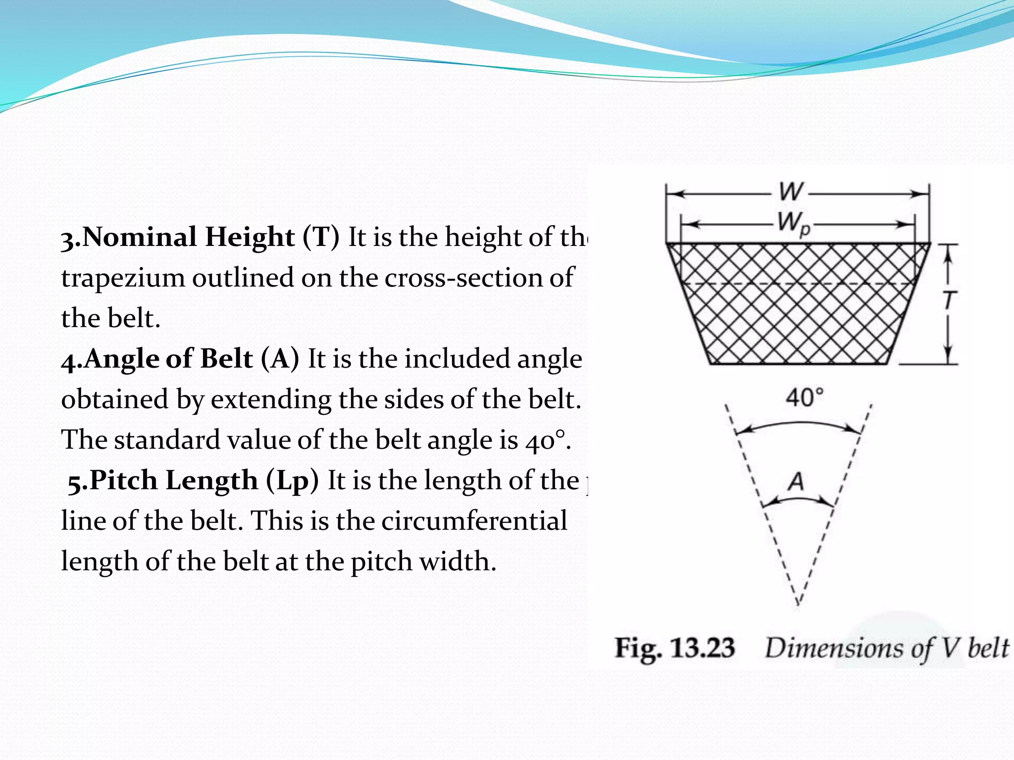
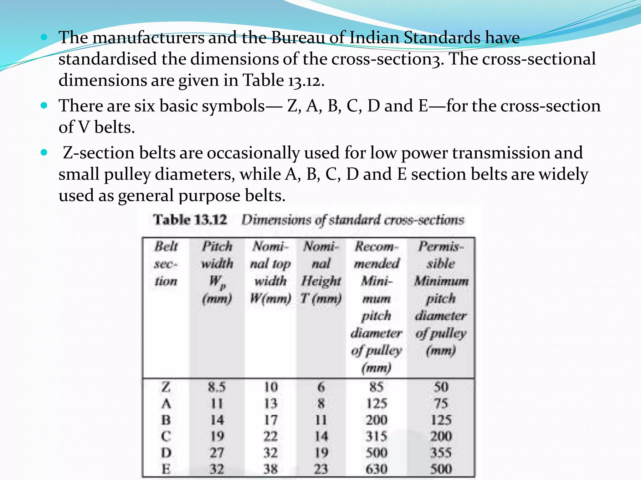
Selection of V belt-drive
Made by:
Achyuth (117ME0008)
Sai Surya (117ME0009)
V-belt drives:
The dimensions for the cross-section of V-belt are shown in Fig. 13.23.
The following notations are used for the dimensions of the cross-
section:
1.Pitch Width (Wp) It is the width of the belt
at its pitch zone. This is the basic dimension
for standardisation of belt and corresponding
pulley groove.
2.Nominal Top Width (W) It is the top width of
the trapezium outlined on the cross-section
of the belt.
3.Nominal Height (T) It is the height of the
trapezium outlined on the cross-section of
the belt.
4.Angle of Belt (A) It is the included angle
obtained by extending the sides of the belt.
The standard value of the belt angle is 40°.
5.Pitch Length (Lp) It is the length of the pitch
line of the belt. This is the circumferential
length of the belt at the pitch width.
 The manufacturers and the Bureau of Indian Standards have
standardised the dimensions of the cross-section3. The cross-sectional
dimensions are given in Table 13.12.
 There are six basic symbols— Z, A, B, C, D and E—for the cross-section
of V belts.
 Z-section belts are occasionally used for low power transmission and
small pulley diameters, while A, B, C, D and E section belts are widely
used as general purpose belts.
Selection of V-belt drive:
 In practice, the designer has to select a V-belt from the catalogue of the
manufacturer. The following information is required for the selection:
 (i) Type of driving unit
 (ii) Type of driven machine
 (iii) Operational hours per day
 (iv) Power to be transmitted
 (v) Input and output speeds
 (vi) Approximate centre distance depending upon the availability of
space
The basic procedure for the selection of V-belts consists of the following
steps:
1. Determine the correction factor according to service (Fa) from Table
13.15. It depends upon the type of driving unit, the type of driven
machine and the operational hours per day.
2. Calculate the design power by the following relationship:
Design power = Fa (transmitted power)
3. Plot a point with design power as X coordinate and input speed
as Y co-ordinate in Fig. 13.24. The location of this point decides
the type of cross-section of the belt. In a borderline case, such as
the point located on the borderline of cross-sections B and C,
alternative calculations are made to find out the best cross-
section.
4. Determine the recommended pitch diameter of the smaller pulley from Table
13.12. It depends upon the cross-section of the belt. Calculate the pitch
diameter of the bigger pulley by the following relationship:
The above values of D and d
are compared with the
preferred pitch diameters
given in Table 13.13. In case
of non-standard value, the
nearest values of d and D
should be taken from
Table 13.13.
5. Determine the pitch length of belt L by the
following relationship,
6. Compare the above value of L with the
preferred pitch length L in Table 13.14. In case
of a non-standard value, the nearest value of
pitch length from Table 13.14 should be taken.
7. Find out the correct centre distance C by
substituting the above value of L in the
following equation:
It is a quadratic equation in C.
L=2𝐶 + +
𝜋(𝐷+𝑑) (𝐷−𝑑)2
2 4𝐶
L=2𝐶 + +
𝜋(𝐷+𝑑) (𝐷−𝑑)2
2 4𝐶
8. Determine the correction factor (Fc) for belt pitch
length from Table 13.21. It depends upon the type of cross
-section and the pitch length of the belt.
9. Calculate the arc of contact for the smaller pulley by the
following relationship:
Determine the correction factor (Fd) for the arc of contact
from Table 13.22. It is not advisable to use an arc of contact
less than 120° for V-belt drive. Therefore, the minimum arc
of contact should be 120°.
10. Depending upon the type of cross-section, refer to the respective table
from Table 13.16 to Table 13.20 and determine the power rating (Pr) of
single V-belt. It depends upon three factors—speed of faster shaft,
pitch diameter of smaller pulley and the speed ratio.
11. The last step in the selection procedure is to find out the number of
belts. It depends upon the design power and the power transmitting
capacity of one belt. The number of belts is
obtained by the following relationship:
Number of belts = 𝑃∗𝐹𝑎
𝑃𝑟∗𝐹𝑐∗𝐹d
 Example : Design a V-belt drive to connect a 7.5 kW, 1440
rpm induction motor to a fan, running at approximately
480 rpm, for a service of 24 h per day. Space is available for
a centre distance of about 1 m.
THANK YOU

Selection of v belt drive

  • 1.
    Selection of Vbelt-drive Made by: Achyuth (117ME0008) Sai Surya (117ME0009)
  • 2.
    V-belt drives: The dimensionsfor the cross-section of V-belt are shown in Fig. 13.23. The following notations are used for the dimensions of the cross- section: 1.Pitch Width (Wp) It is the width of the belt at its pitch zone. This is the basic dimension for standardisation of belt and corresponding pulley groove. 2.Nominal Top Width (W) It is the top width of the trapezium outlined on the cross-section of the belt.
  • 3.
    3.Nominal Height (T)It is the height of the trapezium outlined on the cross-section of the belt. 4.Angle of Belt (A) It is the included angle obtained by extending the sides of the belt. The standard value of the belt angle is 40°. 5.Pitch Length (Lp) It is the length of the pitch line of the belt. This is the circumferential length of the belt at the pitch width.
  • 4.
     The manufacturersand the Bureau of Indian Standards have standardised the dimensions of the cross-section3. The cross-sectional dimensions are given in Table 13.12.  There are six basic symbols— Z, A, B, C, D and E—for the cross-section of V belts.  Z-section belts are occasionally used for low power transmission and small pulley diameters, while A, B, C, D and E section belts are widely used as general purpose belts.
  • 5.
    Selection of V-beltdrive:  In practice, the designer has to select a V-belt from the catalogue of the manufacturer. The following information is required for the selection:  (i) Type of driving unit  (ii) Type of driven machine  (iii) Operational hours per day  (iv) Power to be transmitted  (v) Input and output speeds  (vi) Approximate centre distance depending upon the availability of space
  • 6.
    The basic procedurefor the selection of V-belts consists of the following steps: 1. Determine the correction factor according to service (Fa) from Table 13.15. It depends upon the type of driving unit, the type of driven machine and the operational hours per day.
  • 7.
    2. Calculate thedesign power by the following relationship: Design power = Fa (transmitted power) 3. Plot a point with design power as X coordinate and input speed as Y co-ordinate in Fig. 13.24. The location of this point decides the type of cross-section of the belt. In a borderline case, such as the point located on the borderline of cross-sections B and C, alternative calculations are made to find out the best cross- section.
  • 8.
    4. Determine therecommended pitch diameter of the smaller pulley from Table 13.12. It depends upon the cross-section of the belt. Calculate the pitch diameter of the bigger pulley by the following relationship: The above values of D and d are compared with the preferred pitch diameters given in Table 13.13. In case of non-standard value, the nearest values of d and D should be taken from Table 13.13.
  • 9.
    5. Determine thepitch length of belt L by the following relationship, 6. Compare the above value of L with the preferred pitch length L in Table 13.14. In case of a non-standard value, the nearest value of pitch length from Table 13.14 should be taken. 7. Find out the correct centre distance C by substituting the above value of L in the following equation: It is a quadratic equation in C. L=2𝐶 + + 𝜋(𝐷+𝑑) (𝐷−𝑑)2 2 4𝐶 L=2𝐶 + + 𝜋(𝐷+𝑑) (𝐷−𝑑)2 2 4𝐶
  • 10.
    8. Determine thecorrection factor (Fc) for belt pitch length from Table 13.21. It depends upon the type of cross -section and the pitch length of the belt. 9. Calculate the arc of contact for the smaller pulley by the following relationship: Determine the correction factor (Fd) for the arc of contact from Table 13.22. It is not advisable to use an arc of contact less than 120° for V-belt drive. Therefore, the minimum arc of contact should be 120°.
  • 11.
    10. Depending uponthe type of cross-section, refer to the respective table from Table 13.16 to Table 13.20 and determine the power rating (Pr) of single V-belt. It depends upon three factors—speed of faster shaft, pitch diameter of smaller pulley and the speed ratio. 11. The last step in the selection procedure is to find out the number of belts. It depends upon the design power and the power transmitting capacity of one belt. The number of belts is obtained by the following relationship: Number of belts = 𝑃∗𝐹𝑎 𝑃𝑟∗𝐹𝑐∗𝐹d
  • 12.
     Example :Design a V-belt drive to connect a 7.5 kW, 1440 rpm induction motor to a fan, running at approximately 480 rpm, for a service of 24 h per day. Space is available for a centre distance of about 1 m.
  • 13.