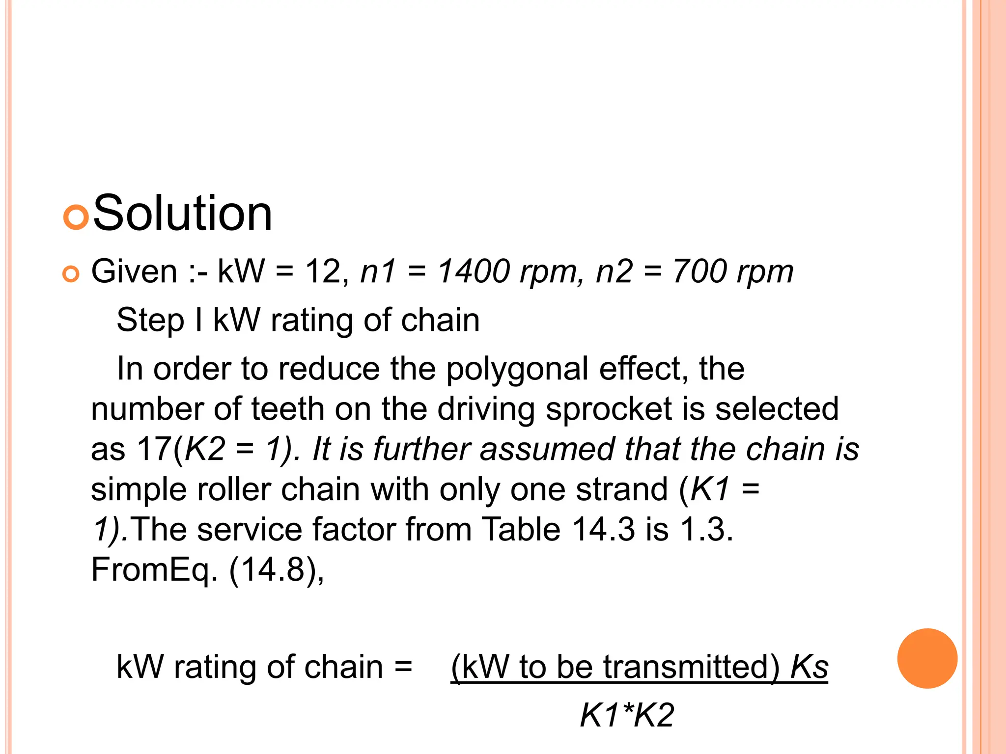
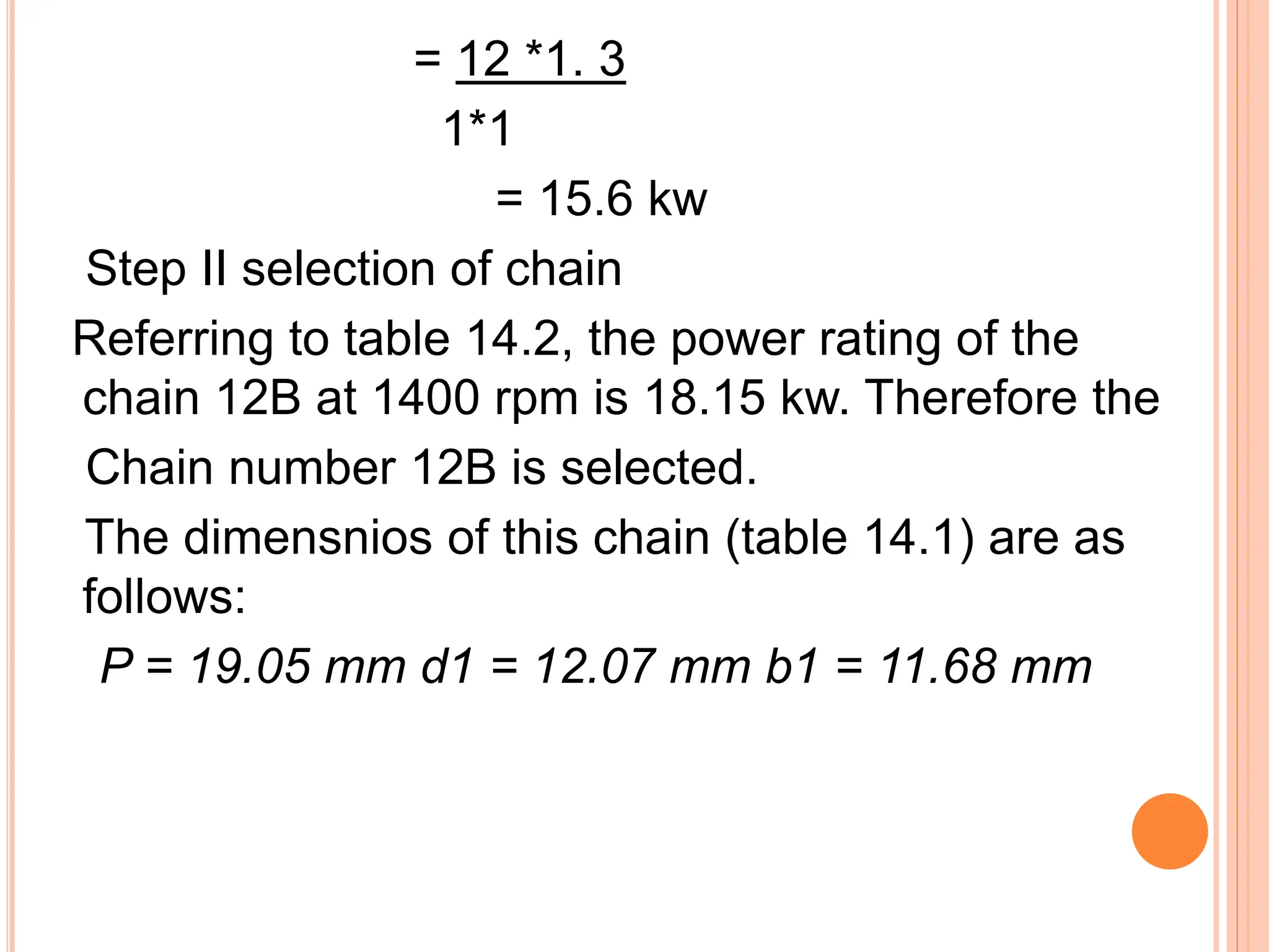
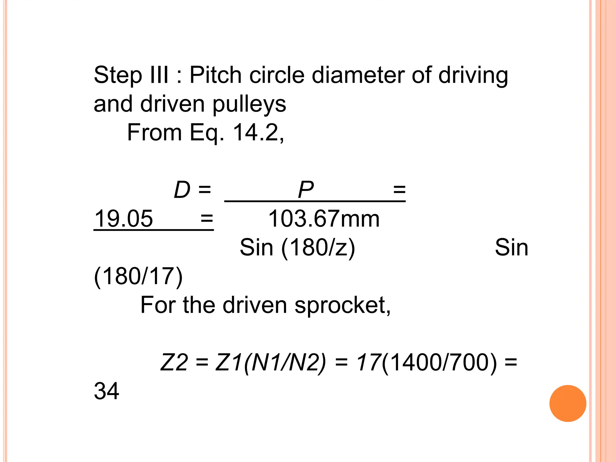
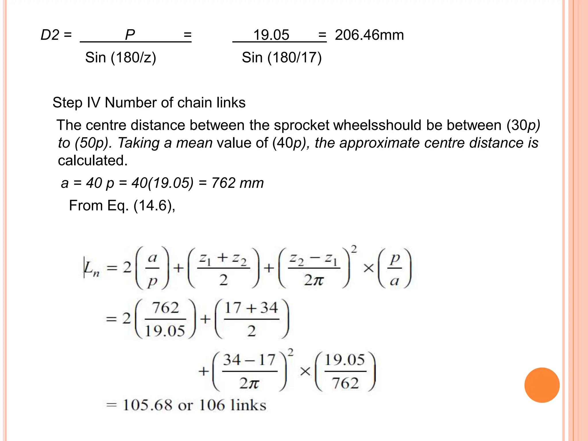
CHAIN DRIVE
Guided By
Prof. H. D. Mhatre
Presented By,
13) Girish Bonde
15) Pratik Chaudhari
16) Rahul chaure
https://studio.youtube.com/channel/U
CJp3a0R2k_lWlOnoXy5sukA
CONTENT
 Introduction
 Types of Belt Drive
 Advantages
 Disadvantages
 Application
 Manufacturer’s catalog
INTRODUCTION
 Transfer power (torque) from one location to
another.
 From driver: motor , peddles, engine , windmill ,
turbine to driven: conveyor belt , back wheels/bike ,
generator rock crusher , dryer.
 Used to span large distances
 Gear drives have a higher torque capability but not
flexible or cheap.
CHAIN DRIVE IN MOTORCYCLE
CHAIN DRIVE IN JCB
TYPES OF CHAINS
ROLLER CHAIN CONSTRUCTION
(MOST COMMON TYPE)
APPLICATION
 Used in bicycles and motorcycles.
 Conveyors.
 Textile industry.
 Chain pumps.
 Rolling mills.
MANUFACTURER’S CATALOG
Selection Procedure And
Formulae
Example:-
 It is required to design a chain drive to connect a
12 kW, 1400 rpm electric motor to a centrifugal
pump running at 700 rpm. These conditions
involve moderate shocks.
(i) Select a proper roller chain and give a list of its
dimensions.
(ii) Determine the pitch circle diameters of driving
and driven sprockets.
(iii) Determine the number of chain links.
(iv) Specify the correct centre distance between
the axes of sprockets.
Solution
 Given :- kW = 12, n1 = 1400 rpm, n2 = 700 rpm
Step I kW rating of chain
In order to reduce the polygonal effect, the
number of teeth on the driving sprocket is selected
as 17(K2 = 1). It is further assumed that the chain is
simple roller chain with only one strand (K1 =
1).The service factor from Table 14.3 is 1.3.
FromEq. (14.8),
kW rating of chain = (kW to be transmitted) Ks
K1*K2
= 12 *1. 3
1*1
= 15.6 kw
Step II selection of chain
Referring to table 14.2, the power rating of the
chain 12B at 1400 rpm is 18.15 kw. Therefore the
Chain number 12B is selected.
The dimensnios of this chain (table 14.1) are as
follows:
P = 19.05 mm d1 = 12.07 mm b1 = 11.68 mm
Step III : Pitch circle diameter of driving
and driven pulleys
From Eq. 14.2,
D = P =
19.05 = 103.67mm
Sin (180/z) Sin
(180/17)
For the driven sprocket,
Z2 = Z1(N1/N2) = 17(1400/700) =
34
D2 = P = 19.05 = 206.46mm
Sin (180/z) Sin (180/17)
Step IV Number of chain links
The centre distance between the sprocket wheelsshould be between (30p)
to (50p). Taking a mean value of (40p), the approximate centre distance is
calculated.
a = 40 p = 40(19.05) = 762 mm
From Eq. (14.6),
Step V Correct centre distance
To provide small sag, for allowing the chain links to take
the best position on the sprocket teeth, the centre
distance is reduced by (0.002a).
Therefore, the correct centre distance is given by,
a = 0.998 Y 765.03 = 763.5 mm
Chain drive ppt types working principle pptpptx

Chain drive ppt types working principle pptpptx

  • 1.
    CHAIN DRIVE Guided By Prof.H. D. Mhatre Presented By, 13) Girish Bonde 15) Pratik Chaudhari 16) Rahul chaure
  • 2.
  • 3.
    CONTENT  Introduction  Typesof Belt Drive  Advantages  Disadvantages  Application  Manufacturer’s catalog
  • 4.
    INTRODUCTION  Transfer power(torque) from one location to another.  From driver: motor , peddles, engine , windmill , turbine to driven: conveyor belt , back wheels/bike , generator rock crusher , dryer.  Used to span large distances  Gear drives have a higher torque capability but not flexible or cheap.
  • 5.
    CHAIN DRIVE INMOTORCYCLE CHAIN DRIVE IN JCB
  • 6.
  • 7.
  • 8.
    APPLICATION  Used inbicycles and motorcycles.  Conveyors.  Textile industry.  Chain pumps.  Rolling mills.
  • 9.
    MANUFACTURER’S CATALOG Selection ProcedureAnd Formulae Example:-  It is required to design a chain drive to connect a 12 kW, 1400 rpm electric motor to a centrifugal pump running at 700 rpm. These conditions involve moderate shocks. (i) Select a proper roller chain and give a list of its dimensions. (ii) Determine the pitch circle diameters of driving and driven sprockets. (iii) Determine the number of chain links. (iv) Specify the correct centre distance between the axes of sprockets.
  • 10.
    Solution  Given :-kW = 12, n1 = 1400 rpm, n2 = 700 rpm Step I kW rating of chain In order to reduce the polygonal effect, the number of teeth on the driving sprocket is selected as 17(K2 = 1). It is further assumed that the chain is simple roller chain with only one strand (K1 = 1).The service factor from Table 14.3 is 1.3. FromEq. (14.8), kW rating of chain = (kW to be transmitted) Ks K1*K2
  • 14.
    = 12 *1.3 1*1 = 15.6 kw Step II selection of chain Referring to table 14.2, the power rating of the chain 12B at 1400 rpm is 18.15 kw. Therefore the Chain number 12B is selected. The dimensnios of this chain (table 14.1) are as follows: P = 19.05 mm d1 = 12.07 mm b1 = 11.68 mm
  • 15.
    Step III :Pitch circle diameter of driving and driven pulleys From Eq. 14.2, D = P = 19.05 = 103.67mm Sin (180/z) Sin (180/17) For the driven sprocket, Z2 = Z1(N1/N2) = 17(1400/700) = 34
  • 16.
    D2 = P= 19.05 = 206.46mm Sin (180/z) Sin (180/17) Step IV Number of chain links The centre distance between the sprocket wheelsshould be between (30p) to (50p). Taking a mean value of (40p), the approximate centre distance is calculated. a = 40 p = 40(19.05) = 762 mm From Eq. (14.6),
  • 17.
    Step V Correctcentre distance To provide small sag, for allowing the chain links to take the best position on the sprocket teeth, the centre distance is reduced by (0.002a). Therefore, the correct centre distance is given by, a = 0.998 Y 765.03 = 763.5 mm