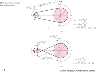
This document provides an overview and examples of belt and chain drives for mechanical analysis. It discusses:
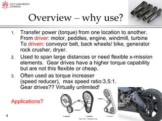
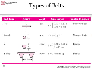
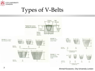
- Types of belts including V-belts, timing belts, and flat belts.
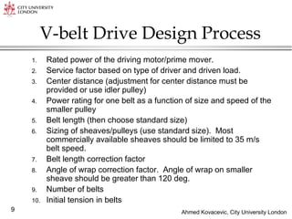
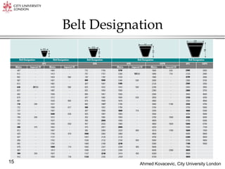
- Belt drive design process including determining power rating, belt length, pulley sizing, and tension. Key equations provided.
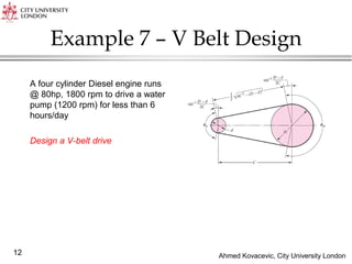
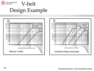
- An example design of a V-belt drive for a diesel engine and water pump.
- Types of chains and chain drive design process including sprocket tooth numbers, speed ratio, center distance, and contact angle.
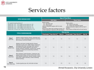
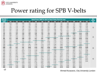
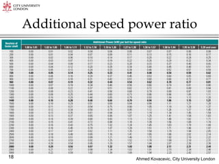
- Standard chain sizes and power ratings. An example design of a chain drive selection and calculations.
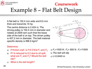
- A flat belt example problem determining belt specifications for a

![Ahmed Kovacevic, City University London
10
Key Equations
Belt speed (no slip) [m/s]
Speed ratio
Belt length [m]
Centre distance [m]
2
2 2
1
1
1
2
2 2
( )
2 ( )
2 4
32( )
16
4 2 ( )
2sin
2
2sin
2
d
D
b D D d d
D
b D
d
d
D
R R
D
Dn
d
D d
L C D d
C
B B D d
C
B L D d
D d
C
D d
C
Recommended:
D < C < 3(D+d)
Use standard lengths](https://image.slidesharecdn.com/mechanicalanalysisbeltandchaindrives-230210203558-9ea7abd4/85/Mechanical-Analysis-Belt-and-chain-drives-pdf-10-320.jpg)
![Ahmed Kovacevic, City University London
11
Forces
1 2
1 2
1
2
2
'
'
'
1 2
( )
( )
2
( )
2
ow b
f
c
c
c b
i c
P F F
d
T F F
F F
e
F F
F m
w bt
m
g g
F F
F F
Transmitted power [W]
Torque [Nm]
Centrifugal force [N]
Mass per unit length
Initial belt tension [N]](https://image.slidesharecdn.com/mechanicalanalysisbeltandchaindrives-230210203558-9ea7abd4/85/Mechanical-Analysis-Belt-and-chain-drives-pdf-11-320.jpg)
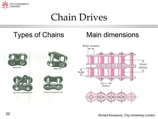
![Ahmed Kovacevic, City University London
23
P – pitch
– pitch angle
/2 – angle of articulation
D – pitch diameter
e – cordial rise (factor for smoothness)
2
1 1
1 2
2
sin 2 sin
/ 60
2
2
4
30 50
p p
D
N
v Npn
N N
L C N N
p p C
p
C
p
L – chain length
v – chain speed
N number of teeth in the sprocket
n – [rpm]](https://image.slidesharecdn.com/mechanicalanalysisbeltandchaindrives-230210203558-9ea7abd4/85/Mechanical-Analysis-Belt-and-chain-drives-pdf-23-320.jpg)


![ME 312 Mechanical Machine Design [Screws, Bolts, Nuts]](https://cdn.slidesharecdn.com/ss_thumbnails/me312-dsulec10-screws-170213050612-thumbnail.jpg?width=640&height=640&fit=bounds)