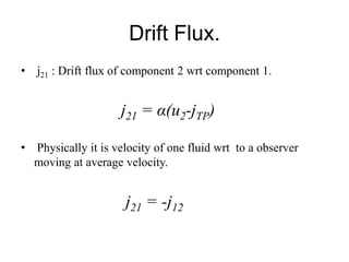
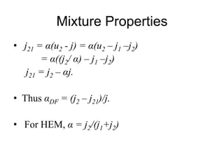
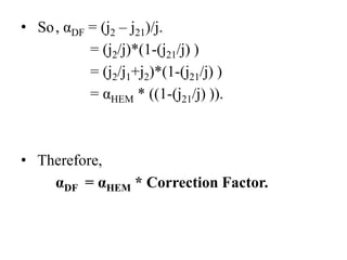
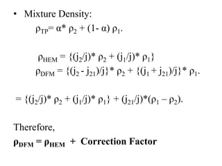
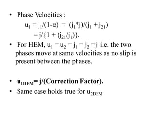
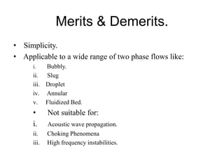
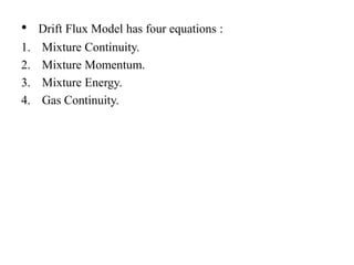
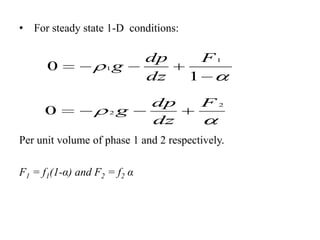
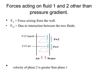
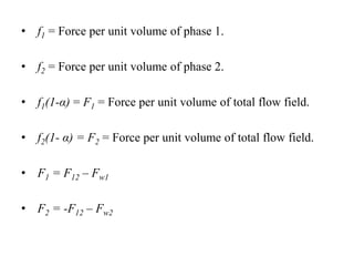
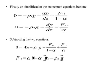
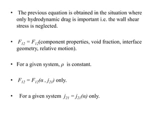
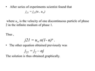
Drift Flux Model
By: Yadav Gaurav N
M.Tech Thermal Sciences

Project Guide:
Dr. S.Jayaraj
Introduction
• DFM is essentially a seperated flow model in which
attention is focused on the relative motion rather than the
motion of the individual phase motion.
• Important assumption associated with the DFM is that the
dynamics of two phases can be expressed by the mixture
momentum equation.
• It modifies all the mixture properties of HEM by suitable
correction factor.
Drift Flux.
• j21 : Drift flux of component 2 wrt component 1.

j21 = α(u2-jTP)
• Physically it is velocity of one fluid wrt to a observer
moving at average velocity.

j21 = -j12
Mixture Properties
• j21 = α(u2 - j) = α(u2 – j1 –j2)
= α((j2/ α) – j1 –j2)
j21 = j2 – αj.

• Thus αDF = (j2 – j21)/j.
• For HEM, α = j2/(j1+j2)
• So , αDF = (j2 – j21)/j.
= (j2/j)*(1-(j21/j) )
= (j2/j1+j2)*(1-(j21/j) )
= αHEM * ((1-(j21/j) )).

• Therefore,
αDF = αHEM * Correction Factor.
• Mixture Density:
ρTP= α* ρ2 + (1- α) ρ1.
ρHEM = {(j2/j)* ρ2 + (j1/j)* ρ1}
ρDFM = {(j2 - j21)/j}* ρ2 + {(j1 + j21)/j}* ρ1.
= {(j2/j)* ρ2 + (j1/j)* ρ1} + (j21/j)*(ρ1 – ρ2).

Therefore,
ρDFM = ρHEM + Correction Factor
• Phase Velocities :
u1 = j1/(1-α) = (j1*j)/(j1 + j21)
= j/{1 + (j21/j1)}.
• For HEM, u1 = u2 = j1 = j2 =j i.e. the two
phases move at same velocities as no slip is
present between the phases.
• u1DFM= j/(Correction Factor).
• Same case holds true for u2DFM
Merits & Demerits.
• Simplicity.
• Applicable to a wide range of two phase flows like:
Bubbly.
ii. Slug
iii. Droplet
iv. Annular
v. Fluidized Bed.
i.

•
i.
ii.
iii.

Not suitable for:
Acoustic wave propagation.
Choking Phenomena
High frequency instabilities.
•

Drift Flux Model has four equations :

1.
2.
3.
4.

Mixture Continuity.
Mixture Momentum.
Mixture Energy.
Gas Continuity.
Approach to estimate j21 by kinematic
constitutive equation
• There are two ways :
1. Concentrate mixture as a whole and apply the laws to
them rather than individual phases.
2. Two fluid formulation.

• Generally two fluids are not in thermal equilibrium. So we
cannot define Tmix and other mixture properties.
• Whether the dispersed flow exhibits bubbly, churn , slug
etc influence the constitutive laws. But the type of flow
changes continuously. So the laws to be applied also
changes.
Two Fluid Formulation.
• Momentum Equation:
u1
t

u1

u1

b1

u
t

u2

u2

b2

f

f

1

2

p

p

f’s are the left over forces which have to be incorporated to
keep the account straight.
• For Newtonian fluid incompressible one component and no
phase change :

f1
•
1.
2.
3.
4.

2

1

Generally f’s arise from:
Wall shear stress.
Particle particle interaction.
Hydrodynamic drag.
Forces during momentum changes during evaporation and
condensation.
• For steady state 1-D conditions:

0

0

1

g

2

g

dp
dz
dp
dz

F1
1
F2

Per unit volume of phase 1 and 2 respectively.
F1 = f1(1-α) and F2 = f2 α
Forces acting on fluid 1 and 2 other than
pressure gradient.
•

Fw = Force arising from the wall.

• F12 = Due to interaction between the two fluids.

•

velocity of phase 2 is greater than phase 1
• f1 = Force per unit volume of phase 1.
• f2 = Force per unit volume of phase 2.
• f1(1-α) = F1 = Force per unit volume of total flow field.
• f2(1- α) = F2 = Force per unit volume of total flow field.
• F1 = F12 – Fw1

• F2 = -F12 – Fw2
• Finally on simplification the momentum equations become

0

1

0

dp
dz

g

2

dp
dz

g

F 12
1
F 12

• Subtracting the two equations,

0

F 12

2

1

g

F 12
1

F 12

g
• The previous equation is obtained in the situation where
only hydrodynamic drag is important i.e. the wall shear
stress is neglected.
• F12 = F12(component properties, void fraction, interface
geometry, relative motion).
• For a given system, ρ is constant.
• F12 = F12(α , j21) only.
•

For a given system j21 = j21(α) only.
• After series of experiments scientist found that
j21 = j21(α , u∞)
where u∞ is the velocity of one discontinuous particle of phase
2 in the infinite medium of phase 1.
Thus ,

j21 = u∞ α(1- α)n .
• The other equation obtained previously was

j21 = j2 – αj
The solution is thus obtained graphically.

Drift flux model

  • 1.
    Drift Flux Model By:Yadav Gaurav N M.Tech Thermal Sciences Project Guide: Dr. S.Jayaraj
  • 2.
    Introduction • DFM isessentially a seperated flow model in which attention is focused on the relative motion rather than the motion of the individual phase motion. • Important assumption associated with the DFM is that the dynamics of two phases can be expressed by the mixture momentum equation. • It modifies all the mixture properties of HEM by suitable correction factor.
  • 3.
    Drift Flux. • j21: Drift flux of component 2 wrt component 1. j21 = α(u2-jTP) • Physically it is velocity of one fluid wrt to a observer moving at average velocity. j21 = -j12
  • 4.
    Mixture Properties • j21= α(u2 - j) = α(u2 – j1 –j2) = α((j2/ α) – j1 –j2) j21 = j2 – αj. • Thus αDF = (j2 – j21)/j. • For HEM, α = j2/(j1+j2)
  • 5.
    • So ,αDF = (j2 – j21)/j. = (j2/j)*(1-(j21/j) ) = (j2/j1+j2)*(1-(j21/j) ) = αHEM * ((1-(j21/j) )). • Therefore, αDF = αHEM * Correction Factor.
  • 6.
    • Mixture Density: ρTP=α* ρ2 + (1- α) ρ1. ρHEM = {(j2/j)* ρ2 + (j1/j)* ρ1} ρDFM = {(j2 - j21)/j}* ρ2 + {(j1 + j21)/j}* ρ1. = {(j2/j)* ρ2 + (j1/j)* ρ1} + (j21/j)*(ρ1 – ρ2). Therefore, ρDFM = ρHEM + Correction Factor
  • 7.
    • Phase Velocities: u1 = j1/(1-α) = (j1*j)/(j1 + j21) = j/{1 + (j21/j1)}. • For HEM, u1 = u2 = j1 = j2 =j i.e. the two phases move at same velocities as no slip is present between the phases. • u1DFM= j/(Correction Factor). • Same case holds true for u2DFM
  • 8.
    Merits & Demerits. •Simplicity. • Applicable to a wide range of two phase flows like: Bubbly. ii. Slug iii. Droplet iv. Annular v. Fluidized Bed. i. • i. ii. iii. Not suitable for: Acoustic wave propagation. Choking Phenomena High frequency instabilities.
  • 9.
    • Drift Flux Modelhas four equations : 1. 2. 3. 4. Mixture Continuity. Mixture Momentum. Mixture Energy. Gas Continuity.
  • 10.
    Approach to estimatej21 by kinematic constitutive equation • There are two ways : 1. Concentrate mixture as a whole and apply the laws to them rather than individual phases. 2. Two fluid formulation. • Generally two fluids are not in thermal equilibrium. So we cannot define Tmix and other mixture properties. • Whether the dispersed flow exhibits bubbly, churn , slug etc influence the constitutive laws. But the type of flow changes continuously. So the laws to be applied also changes.
  • 11.
    Two Fluid Formulation. •Momentum Equation: u1 t u1 u1 b1 u t u2 u2 b2 f f 1 2 p p f’s are the left over forces which have to be incorporated to keep the account straight.
  • 12.
    • For Newtonianfluid incompressible one component and no phase change : f1 • 1. 2. 3. 4. 2 1 Generally f’s arise from: Wall shear stress. Particle particle interaction. Hydrodynamic drag. Forces during momentum changes during evaporation and condensation.
  • 13.
    • For steadystate 1-D conditions: 0 0 1 g 2 g dp dz dp dz F1 1 F2 Per unit volume of phase 1 and 2 respectively. F1 = f1(1-α) and F2 = f2 α
  • 14.
    Forces acting onfluid 1 and 2 other than pressure gradient. • Fw = Force arising from the wall. • F12 = Due to interaction between the two fluids. • velocity of phase 2 is greater than phase 1
  • 15.
    • f1 =Force per unit volume of phase 1. • f2 = Force per unit volume of phase 2. • f1(1-α) = F1 = Force per unit volume of total flow field. • f2(1- α) = F2 = Force per unit volume of total flow field. • F1 = F12 – Fw1 • F2 = -F12 – Fw2
  • 16.
    • Finally onsimplification the momentum equations become 0 1 0 dp dz g 2 dp dz g F 12 1 F 12 • Subtracting the two equations, 0 F 12 2 1 g F 12 1 F 12 g
  • 17.
    • The previousequation is obtained in the situation where only hydrodynamic drag is important i.e. the wall shear stress is neglected. • F12 = F12(component properties, void fraction, interface geometry, relative motion). • For a given system, ρ is constant. • F12 = F12(α , j21) only. • For a given system j21 = j21(α) only.
  • 18.
    • After seriesof experiments scientist found that j21 = j21(α , u∞) where u∞ is the velocity of one discontinuous particle of phase 2 in the infinite medium of phase 1. Thus , j21 = u∞ α(1- α)n . • The other equation obtained previously was j21 = j2 – αj The solution is thus obtained graphically.