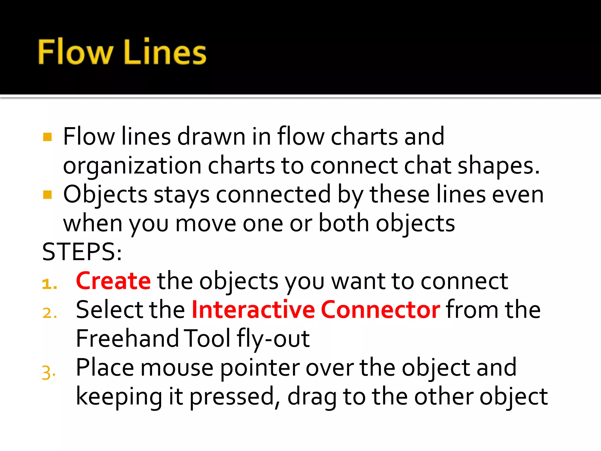
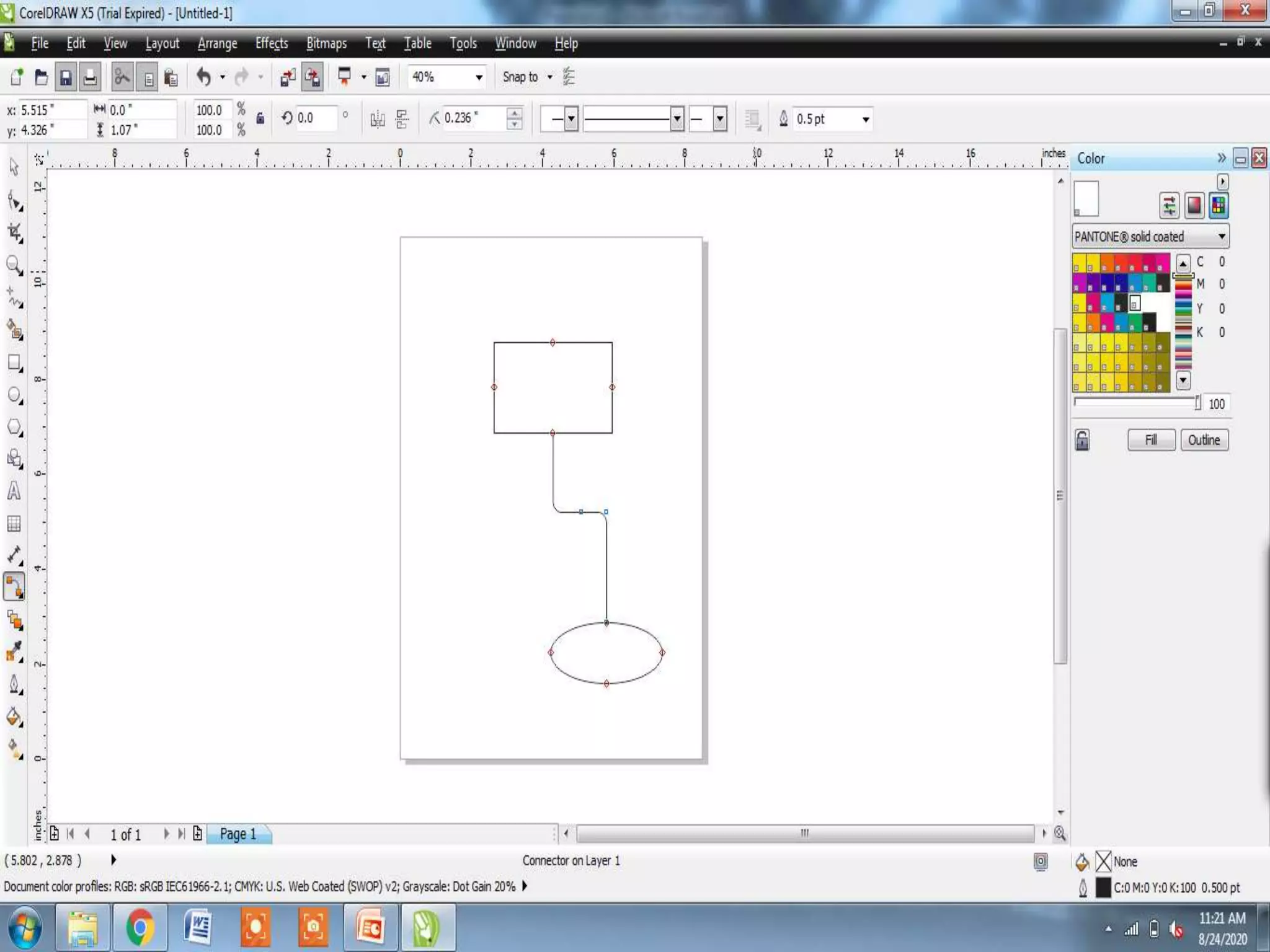
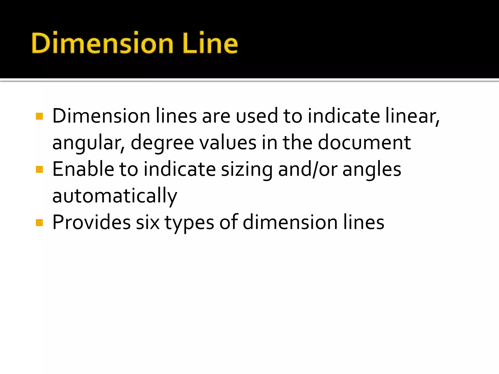
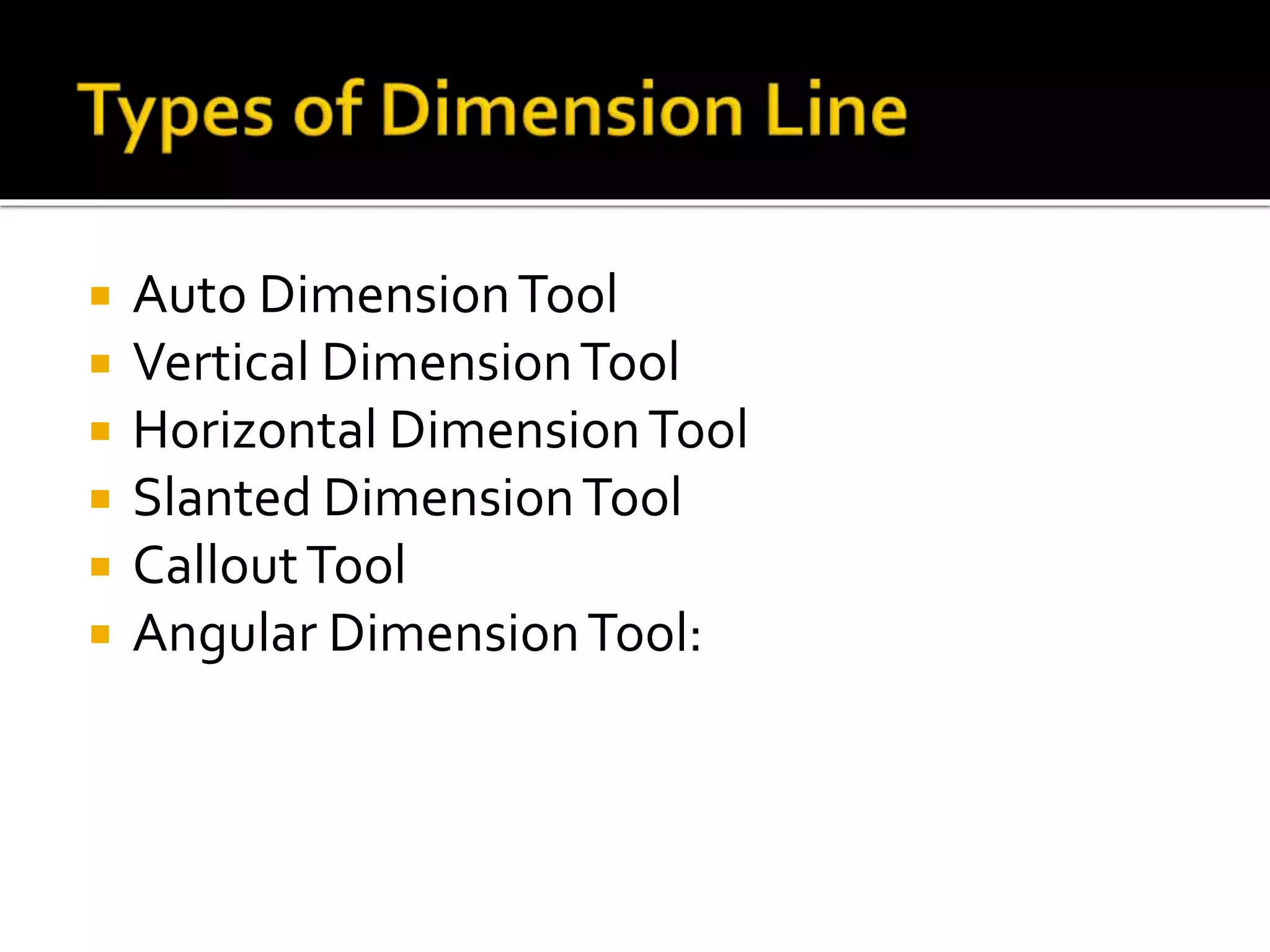
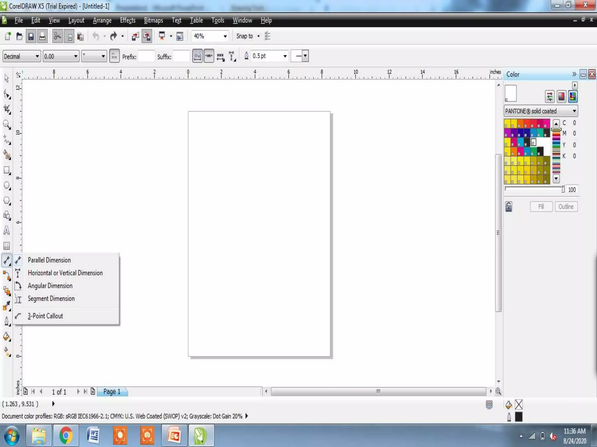
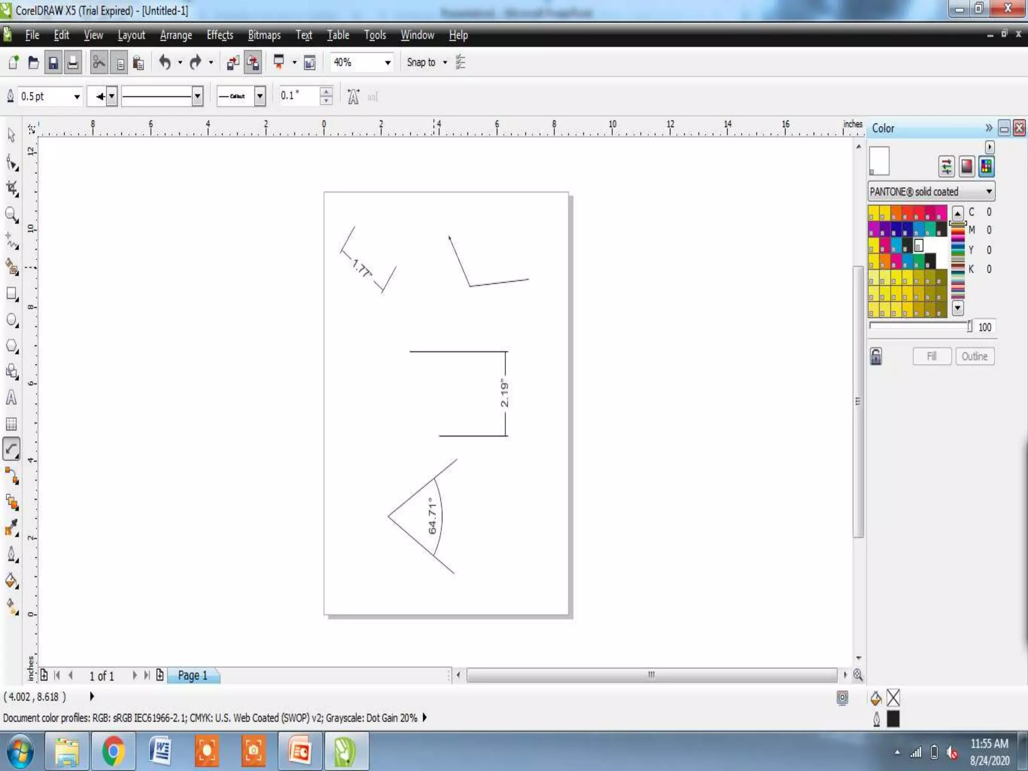
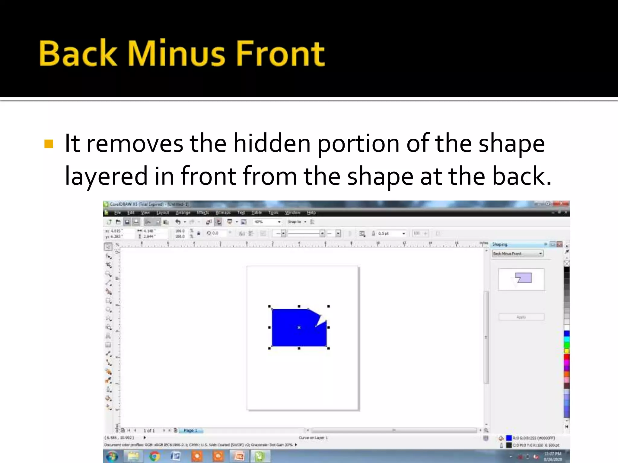
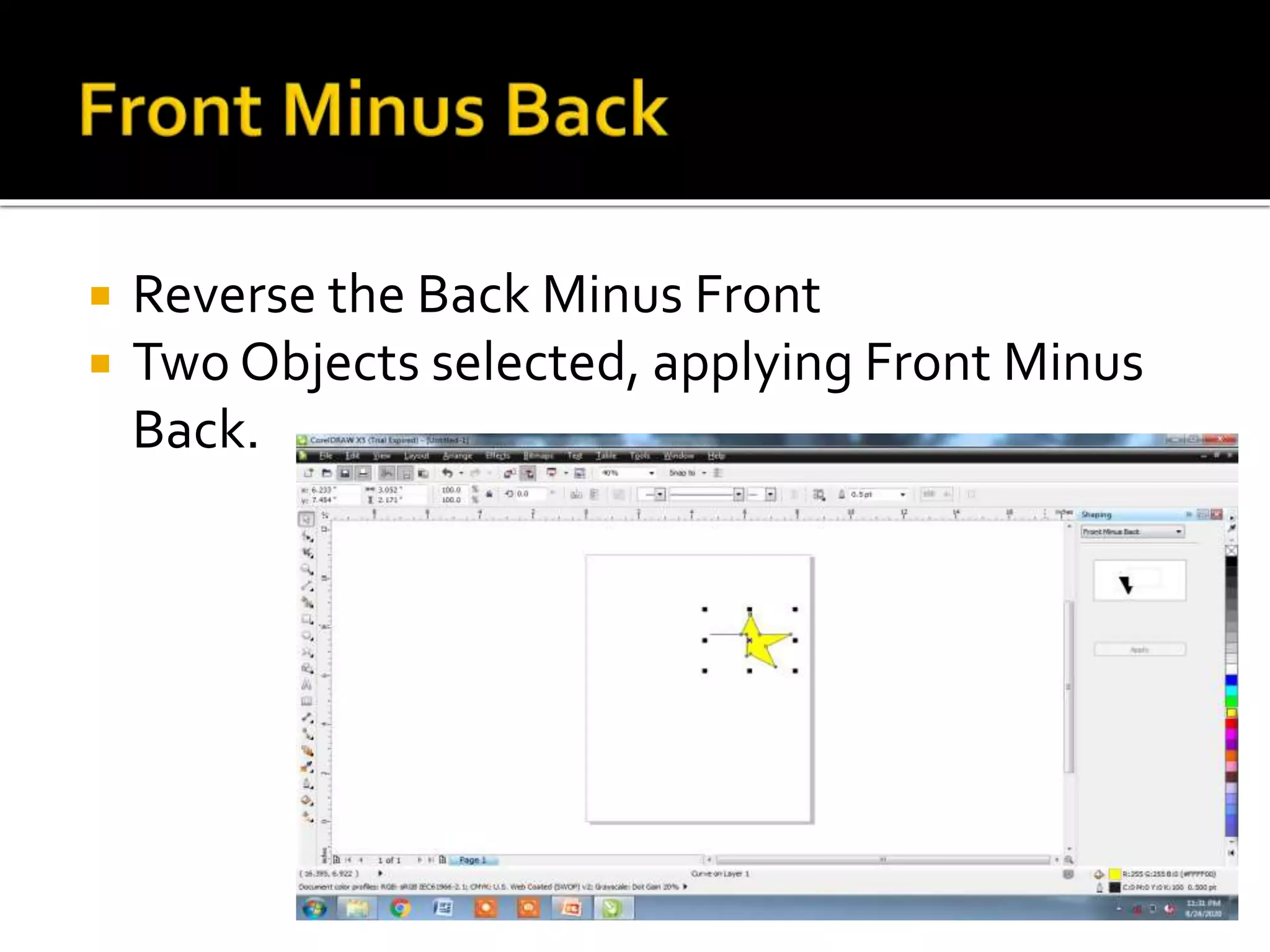
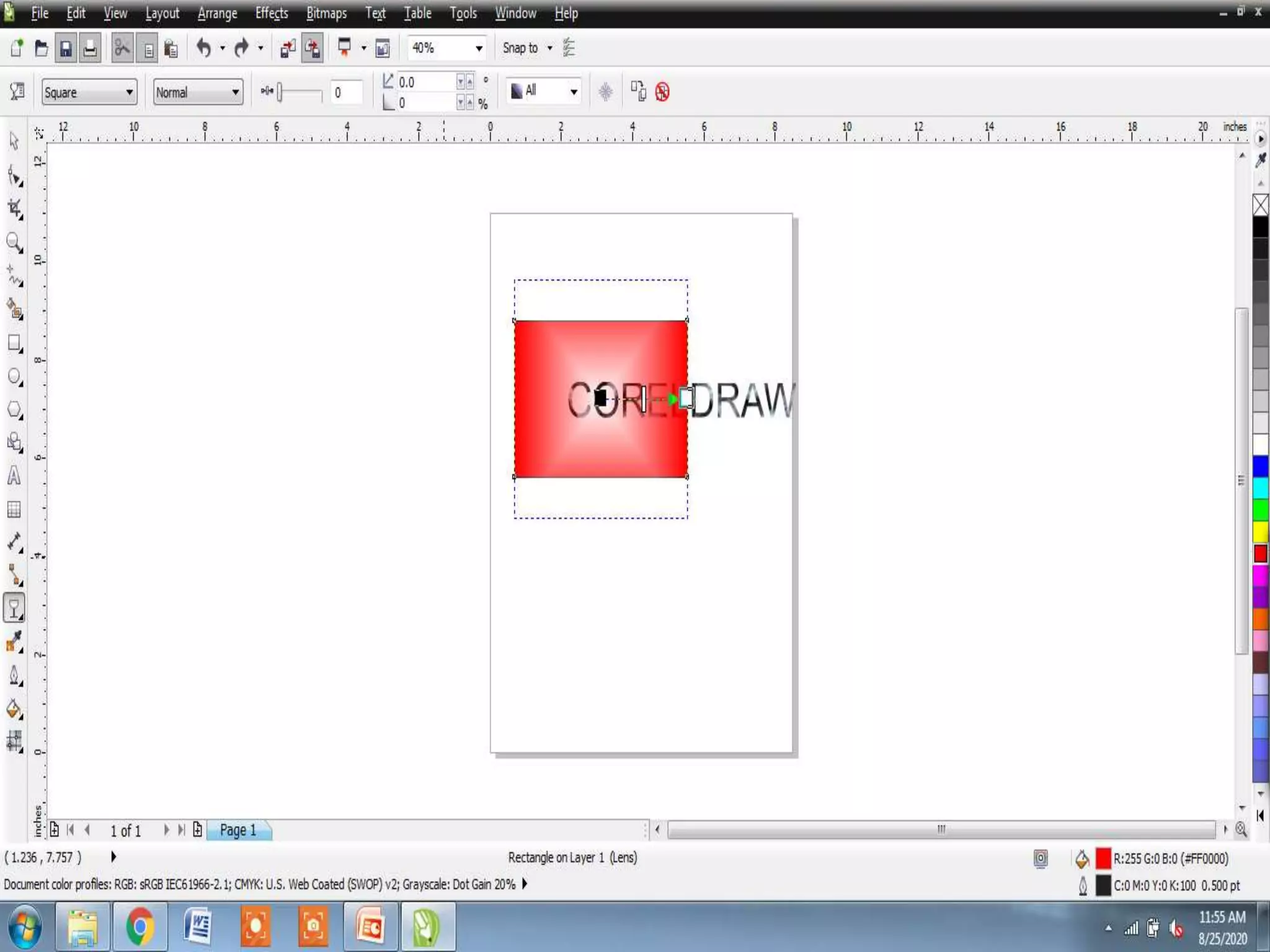
Presented by
V.Santhi,
Department of Computer Application,
Bon Secours College for women,
Thanjavur
 Lines
 DimensionTool
 Formatting Lines and Outlines
 Closing Multiple Line Segments
 Working with Object Shapes
 Transformation Docker
 Adding Effects to Objects
 Explore about the Outlines, Flow lines and
Dimension Lines
 Flow lines drawn in flow charts and
organization charts to connect chat shapes.
 Objects stays connected by these lines even
when you move one or both objects
STEPS:
1. Create the objects you want to connect
2. Select the Interactive Connector from the
FreehandTool fly-out
3. Place mouse pointer over the object and
keeping it pressed, drag to the other object
 Dimension lines are used to indicate linear,
angular, degree values in the document
 Enable to indicate sizing and/or angles
automatically
 Provides six types of dimension lines
 Auto DimensionTool
 Vertical DimensionTool
 Horizontal DimensionTool
 Slanted DimensionTool
 CalloutTool
 Angular DimensionTool:
 Auto DimensionTool:
Creates eitherVertical or Horizontal
Dimension lines, defined by the initial click-
drag action while creating the dimension
lines
 Vertical DimensionTool:
Creates dimension lines with vertically
oriented labels, default 90 degree page
orientation
 Horizontal DimensionTool:
Creates dimension lines with horizontally
oriented labels
 Slanted DimensionTool:
Creates dimension lines that measure
distances at an angle
 CalloutTool:
Used to create lines attached with labels
at various positions
 Angular DimensionTool:
Used to measure the angle between
objects based on degrees, radians or gradients
 Can change the appearance of both line and
outlines
 Can specify with their color, width, style,
corner shape and cap style
 Can remove and create your own line or
outline style by adjusting the distance
between segments in the line
STEPS:
1. Select an object to set the properties for the
outline or a line
2. Open the OutlineTool fly out and click the
Outline Pen Dialog button, this will display
the Outline Pen dialog box.
 Options of Outline Pen Dialog box:
1. Color
2. Width
3. Styles
4. Corner Shape
5. Line caps
 Can create a closed object from line
segments by selecting which lines to connect
and shape of the connecting line.
 Connecting line either straight or curved
 Can connect lines using the start to end
nodes of the line
STEPS:
1. Create two line
2. Hold down Shift key pressed and select
each object using Pick tool
3. Click close path option from the Arrange
menu bar option and click one of the
following
 Closest Nodes with Straight line
 Closest Nodes with Curvy Lines
 Start to End with Straight Lines
 Start to End with Curvy Lines
4. Chose the option, Closest Nodes with
Straight Lines
 Possible to reshape your object like
combining, welding or blending the objects
 Explore the features likeTrim, Intersect, Front
Minus Back, Back Minus Front
 Trim option has the effect of removing a
portion where the objects overlap each other
STEPS:
1. Create the objects and position
them(Overlapped)
2. Select both the objects using Shift key
3. Click window menu and place Dockers
option
4. Select Shaping option to display the
Shaping Docker
5. Choose Trim option in the drop down list
6. Select which object you want to retain after
by clicking the sourcetarget objects
7. Now click Trim in Shaping Docker
8. Finally Click the Object you want to trim
 Intersect object creates a new object based
on the actual overlapping portion of two or
more objects.
STEPS:
1. Repeat the Same steps ofTrim
2. Choose Intersect option in shaping Docker
 It removes the hidden portion of the shape
layered in front from the shape at the back.
 Reverse the Back Minus Front
 Two Objects selected, applying Front Minus
Back.
 Transformation Docker provides options for
positioning, rotating, scaling, sizing and
skewing the objects
 Can position objects by dragging them into a
new location
STEPS:
1. Click on the Window menu bar
2. Inside pull-down menu, place mouse pointer
on the Dockers option
3. Select Transformation docker, in that
specify the values H/V
4. ClickApply button
 Rotating option of theTransformation Docker
enables to rotate objects
STEPS:
1. Repeat steps of 1 & 2 of positing object
2. Select Rotate inTransformation Docker
3. Specify the Angle of Rotation in Angle box
4. Changing H/V values
5. ClickApply
 Scale and Mirror may apply to objects to
change the object size.
STEPS:
1. Click Scale and Mirror inTransformation
Docker
2. Select the object to Scale/ Mirror
3. Change H/VValues
4. ClickApply
 Perspective Effect
 Extrusion
 Drop Shadow
 Distortion
 Transparency of Objects
 Shortening one or two sides of an object
 Gives an object the appearance of receding in
one or two directions, thereby creating a one
point perspective or a two point perspective
STEPS:
1. Select an image with the Pick tool
2. Choose Add Perspective in Effects menu,
object overlaid with horizontal and vertical lines
3. Drag any of the control handles
4. Now Click the page background on any other
object
 Apply a three dimensional perspective by
projecting lines from an object to create the
illusion of depth
 Extrude is applied using the Interactive Extrude
tool in Interactive Blend tool
STEPS:
1. Select the object with the Pick tool
2. Choose Interactive Extrude tool from the
Interactive blend tool
3. Place the Cursor in the center of the object with
the left mouse pointer pressed, drag outward in
any direction.To reset press ESC
 Stimulate light falling on an object or group
of Objects
STEPS:
1. Type the text
2. Select the text using pick tool
3. Choose Interactive Drop Shadow tool in
Interactive Blend fly out
4. Place the cursor on the text and keep
pressed, drag
5. Release the mouse button
 Distortion effects controlled changes to an
object shape.
STEPS:
1. Open Interactive Distortion in Interactive
Blend tool
2. In property bar, click the button for distortion
mode to apply
3. Choose Zipper Distortion
4. Point where you want to place the distortion,
drag
5. Release the mouse button
 Can able to apply a transparency to an object,
it partially visible
 Transparency fills may be, Uniform, fountain,
texture, patterns.
STEPS:
1. Create two objects one is rectangle and
other is Text
2. Fill theText with Pattern Fill and Rectangle
with Uniform Fill
3. Arrange object in overlapped manner
4. Select the rectangle object with pick tool
5. Select the InteractiveTransparency in
Interactive blend tool fly-out
6. In property bar choose transparency as
Uniform
Drawing and Selecting Through Line

Drawing and Selecting Through Line

  • 1.
    Presented by V.Santhi, Department ofComputer Application, Bon Secours College for women, Thanjavur
  • 2.
     Lines  DimensionTool Formatting Lines and Outlines  Closing Multiple Line Segments  Working with Object Shapes  Transformation Docker  Adding Effects to Objects
  • 3.
     Explore aboutthe Outlines, Flow lines and Dimension Lines
  • 4.
     Flow linesdrawn in flow charts and organization charts to connect chat shapes.  Objects stays connected by these lines even when you move one or both objects STEPS: 1. Create the objects you want to connect 2. Select the Interactive Connector from the FreehandTool fly-out 3. Place mouse pointer over the object and keeping it pressed, drag to the other object
  • 6.
     Dimension linesare used to indicate linear, angular, degree values in the document  Enable to indicate sizing and/or angles automatically  Provides six types of dimension lines
  • 7.
     Auto DimensionTool Vertical DimensionTool  Horizontal DimensionTool  Slanted DimensionTool  CalloutTool  Angular DimensionTool:
  • 9.
     Auto DimensionTool: CreateseitherVertical or Horizontal Dimension lines, defined by the initial click- drag action while creating the dimension lines  Vertical DimensionTool: Creates dimension lines with vertically oriented labels, default 90 degree page orientation
  • 10.
     Horizontal DimensionTool: Createsdimension lines with horizontally oriented labels  Slanted DimensionTool: Creates dimension lines that measure distances at an angle  CalloutTool: Used to create lines attached with labels at various positions  Angular DimensionTool: Used to measure the angle between objects based on degrees, radians or gradients
  • 12.
     Can changethe appearance of both line and outlines  Can specify with their color, width, style, corner shape and cap style  Can remove and create your own line or outline style by adjusting the distance between segments in the line
  • 13.
    STEPS: 1. Select anobject to set the properties for the outline or a line 2. Open the OutlineTool fly out and click the Outline Pen Dialog button, this will display the Outline Pen dialog box.
  • 15.
     Options ofOutline Pen Dialog box: 1. Color 2. Width 3. Styles 4. Corner Shape 5. Line caps
  • 17.
     Can createa closed object from line segments by selecting which lines to connect and shape of the connecting line.  Connecting line either straight or curved  Can connect lines using the start to end nodes of the line STEPS: 1. Create two line 2. Hold down Shift key pressed and select each object using Pick tool
  • 18.
    3. Click closepath option from the Arrange menu bar option and click one of the following  Closest Nodes with Straight line  Closest Nodes with Curvy Lines  Start to End with Straight Lines  Start to End with Curvy Lines 4. Chose the option, Closest Nodes with Straight Lines
  • 19.
     Possible toreshape your object like combining, welding or blending the objects  Explore the features likeTrim, Intersect, Front Minus Back, Back Minus Front
  • 20.
     Trim optionhas the effect of removing a portion where the objects overlap each other STEPS: 1. Create the objects and position them(Overlapped) 2. Select both the objects using Shift key 3. Click window menu and place Dockers option 4. Select Shaping option to display the Shaping Docker
  • 21.
    5. Choose Trimoption in the drop down list 6. Select which object you want to retain after by clicking the sourcetarget objects 7. Now click Trim in Shaping Docker 8. Finally Click the Object you want to trim
  • 23.
     Intersect objectcreates a new object based on the actual overlapping portion of two or more objects. STEPS: 1. Repeat the Same steps ofTrim 2. Choose Intersect option in shaping Docker
  • 25.
     It removesthe hidden portion of the shape layered in front from the shape at the back.
  • 26.
     Reverse theBack Minus Front  Two Objects selected, applying Front Minus Back.
  • 27.
     Transformation Dockerprovides options for positioning, rotating, scaling, sizing and skewing the objects
  • 28.
     Can positionobjects by dragging them into a new location STEPS: 1. Click on the Window menu bar 2. Inside pull-down menu, place mouse pointer on the Dockers option 3. Select Transformation docker, in that specify the values H/V 4. ClickApply button
  • 30.
     Rotating optionof theTransformation Docker enables to rotate objects STEPS: 1. Repeat steps of 1 & 2 of positing object 2. Select Rotate inTransformation Docker 3. Specify the Angle of Rotation in Angle box 4. Changing H/V values 5. ClickApply
  • 32.
     Scale andMirror may apply to objects to change the object size. STEPS: 1. Click Scale and Mirror inTransformation Docker 2. Select the object to Scale/ Mirror 3. Change H/VValues 4. ClickApply
  • 34.
     Perspective Effect Extrusion  Drop Shadow  Distortion  Transparency of Objects
  • 35.
     Shortening oneor two sides of an object  Gives an object the appearance of receding in one or two directions, thereby creating a one point perspective or a two point perspective STEPS: 1. Select an image with the Pick tool 2. Choose Add Perspective in Effects menu, object overlaid with horizontal and vertical lines 3. Drag any of the control handles 4. Now Click the page background on any other object
  • 37.
     Apply athree dimensional perspective by projecting lines from an object to create the illusion of depth  Extrude is applied using the Interactive Extrude tool in Interactive Blend tool STEPS: 1. Select the object with the Pick tool 2. Choose Interactive Extrude tool from the Interactive blend tool 3. Place the Cursor in the center of the object with the left mouse pointer pressed, drag outward in any direction.To reset press ESC
  • 39.
     Stimulate lightfalling on an object or group of Objects STEPS: 1. Type the text 2. Select the text using pick tool 3. Choose Interactive Drop Shadow tool in Interactive Blend fly out 4. Place the cursor on the text and keep pressed, drag 5. Release the mouse button
  • 41.
     Distortion effectscontrolled changes to an object shape. STEPS: 1. Open Interactive Distortion in Interactive Blend tool 2. In property bar, click the button for distortion mode to apply 3. Choose Zipper Distortion 4. Point where you want to place the distortion, drag 5. Release the mouse button
  • 43.
     Can ableto apply a transparency to an object, it partially visible  Transparency fills may be, Uniform, fountain, texture, patterns. STEPS: 1. Create two objects one is rectangle and other is Text 2. Fill theText with Pattern Fill and Rectangle with Uniform Fill 3. Arrange object in overlapped manner
  • 44.
    4. Select therectangle object with pick tool 5. Select the InteractiveTransparency in Interactive blend tool fly-out 6. In property bar choose transparency as Uniform