Downloaded 10 times
![International Journal of Modern Engineering Research (IJMER)
www.ijmer.com Vol.3, Issue.2, March-April. 2013 pp-1146-1149 ISSN: 2249-6645
www.ijmer.com 1149 | Page
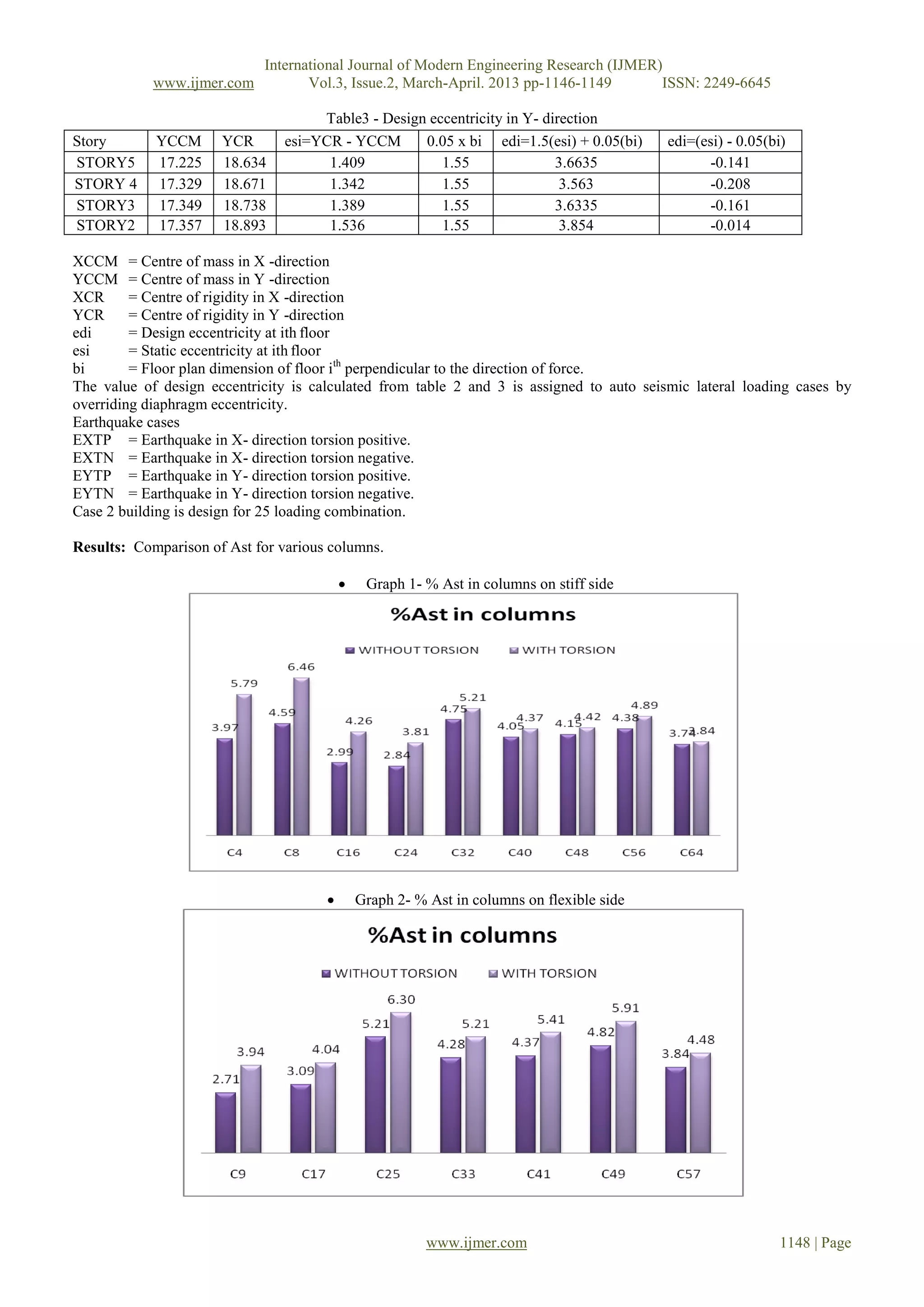
Graph 3- % Ast in columns failed in torsion
IV. Conclusion
In the asymmetric building case 2, it was observed that the forces in the columns located in the stiff side of the plan
are much smaller than those obtained in the elements of the flexible side of the plan. There is no significant change in
column forces around centre of rigidity.
It is observed that column no C2, C3, C6, C7 and C8 in case 2(columns which are farthest from centre of rigidity) while
designing it considering design eccentricity are failed. Column no C25, C26 and C50 (columns on flexible side) are failed in
case 2. (Reinforcement required exceeds maximum allowed).
Most of the designer adopts approximate methods for the torsional analysis of building. However this may be an
inaccurate assessment. Several studies of structural damage during the past earthquake reveal that torsion is the most critical
factor leading to major damage or complete collapse of building. It is, therefore, necessary that irregular buildings should be
analyzed for torsion. A three dimensional analysis using Etab is able to calculate the center of rigidity; by getting these
values we can perform torsional analysis.
References
[1] Bijily B, (2012) Critical evaluation of torsional provision in IS-1893: 2002.
[2] Dutta, S. C., (2001). Effect of Strength Deterioration on Inelastic Seismic Torsional Behaviour of Asymmetric RC Buildings,
Building and Environment, 36(0), 1109-1118. 16.
[3] S. K. Dubey, (2011) Seismic behaviour of asymmetric R C buildings.
[4] H. J. Shah, S. K. Jain, Design example of six storey building.
[5] M.D. Bensalah, et. al., Assessments of the torsion effect in asymmetric buildings under seismic load.(15 WCEE).
[6] Rucha S. Banginwar, M. R. Vyawahare, (2012) Effects of plan configuration on the seismic behaviour of the structure by response
spectrum method.
[7] Rudra Nevatia, Torsional Provisions In IS: 1893(2002)
[8] IS 1893 Part 1, (2002).Indian Standard Criteria for Earthquake Resistant Design of Structures.
[9] S K Jain et. al. Proposed Draft Provision and commentary on Indian seismic code IS 1893 (Part 1).](https://image.slidesharecdn.com/dl3211461149-130507051203-phpapp02/75/Dl3211461149-4-2048.jpg)

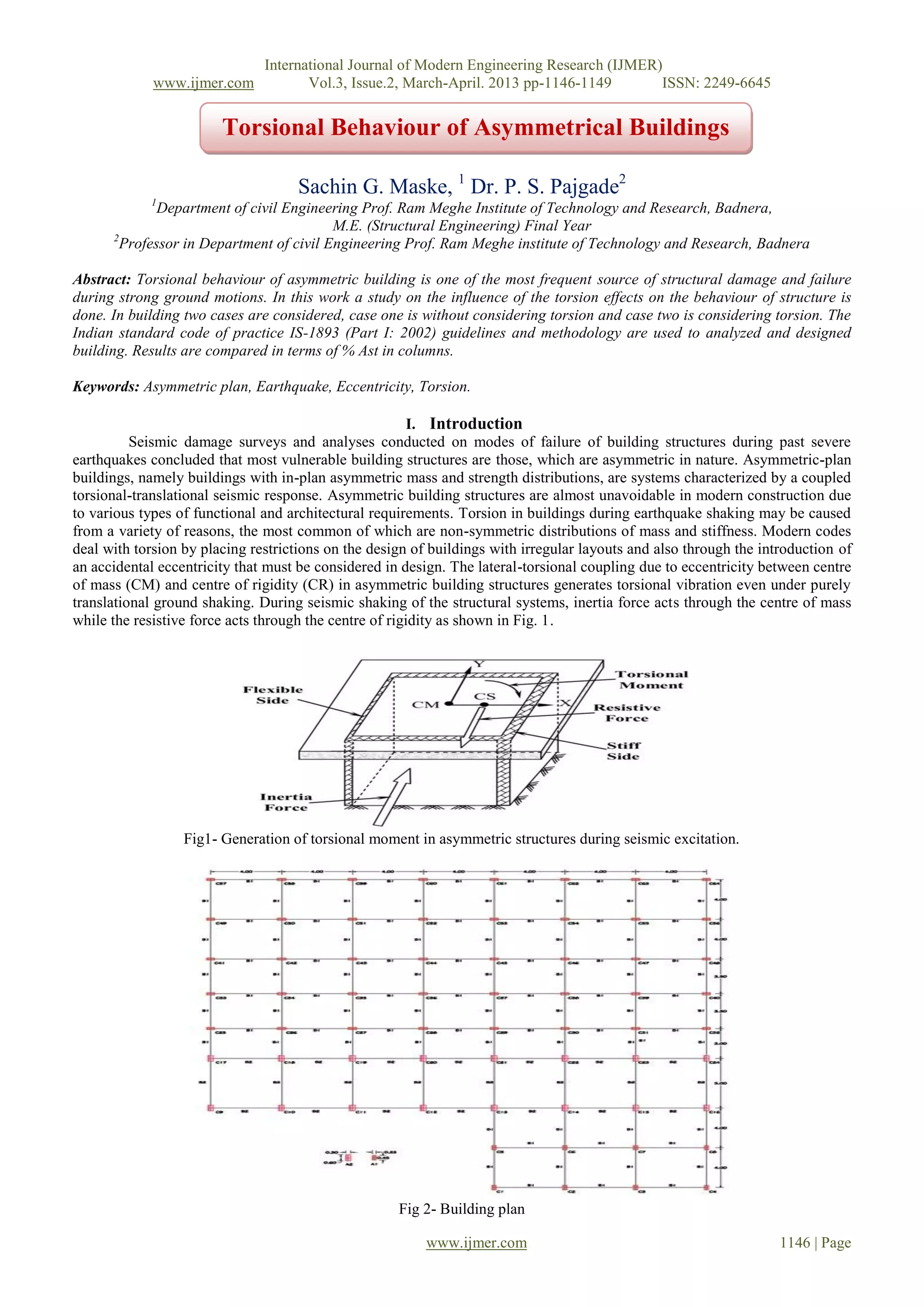
This document analyzes the torsional behavior of asymmetric buildings during earthquakes. It studies a 4-story reinforced concrete building with an irregular plan in two cases: without considering torsion effects, and considering torsion effects by including an accidental eccentricity in the design. The building is modeled and analyzed using the ETab software. Results show that columns on the flexible side of the building require more reinforcement when torsion is considered compared to the stiff side. Several columns fail the design when torsion effects are included that did not fail without considering torsion. The study concludes it is important to consider torsional effects in the analysis and design of irregular asymmetric buildings.


![7 Sem ntcc[1].pptx aaaaaaaaaaaaaaaaaaaaa](https://cdn.slidesharecdn.com/ss_thumbnails/7semntcc1-250525152035-e1e71438-thumbnail.jpg?width=640&height=640&fit=bounds)


