Downloaded 368 times

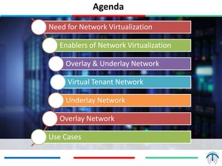
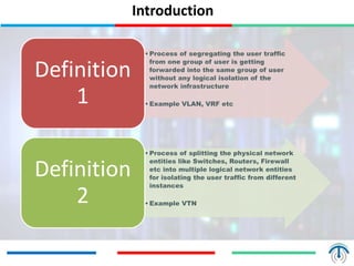
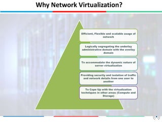
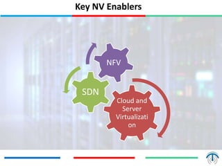
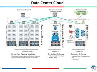
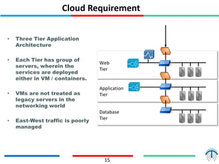
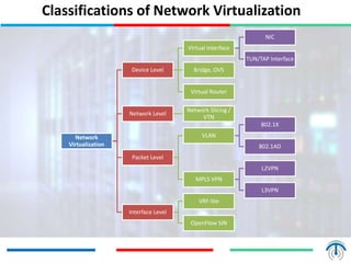
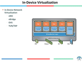
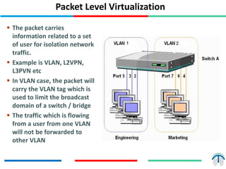
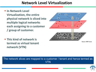
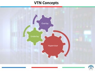
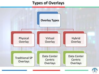
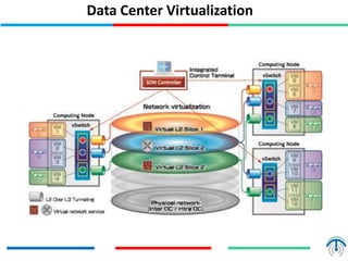
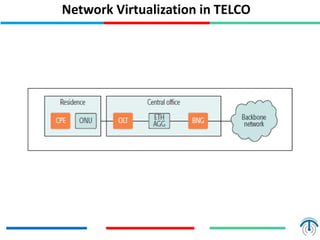
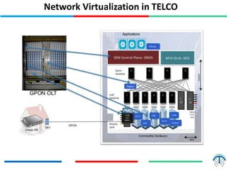

Network virtualization logically separates network resources and allows multiple virtual networks to operate over a shared physical infrastructure. It provides benefits like efficient usage of network resources, logical isolation of traffic between users, and accommodating dynamic server virtualization. Key enablers of network virtualization are cloud computing, server virtualization, software-defined networking (SDN), and network functions virtualization (NFV). A virtual tenant network (VTN) uses an underlay physical network and an overlay virtual network to logically isolate traffic for different users or groups. Common uses of network virtualization are in data centers and telecommunication networks.


![[若渴計畫] Challenges and Solutions of Window Remote Shellcode](https://cdn.slidesharecdn.com/ss_thumbnails/challengesandsolutionsofwindowremoteshellcode-171118141605-thumbnail.jpg?width=640&height=640&fit=bounds)


