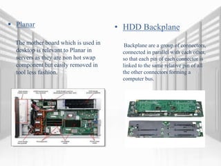
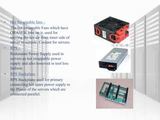
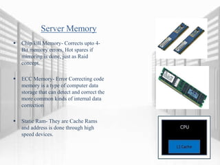
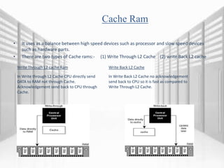
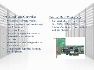
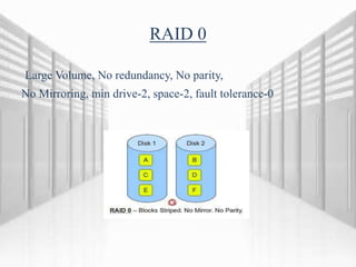
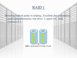
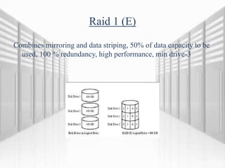
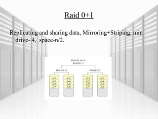
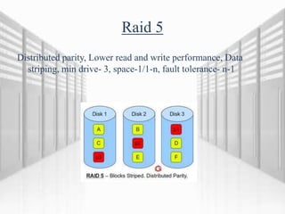
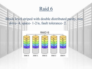
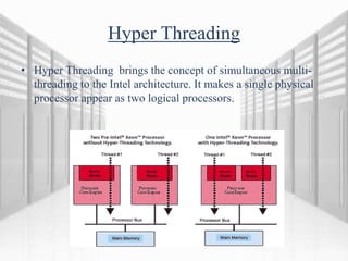
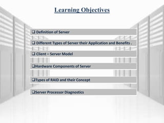
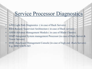
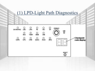
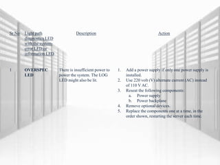
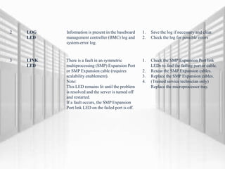
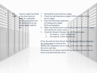
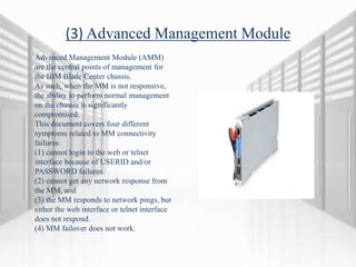
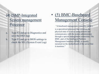
The document provides information about server training, including the basics of servers and server hardware components. It defines what a server is, describes different types of servers based on size and use (e.g. rack mount, tower, blade). It also outlines the client-server model. The hardware components of a server are explained, such as the motherboard, hard drives, fans, power supplies, memory, RAID controllers. Different types of RAID configurations are defined. Finally, it discusses server processor diagnostics using tools like light path diagnostics and baseboard management controllers.
2. Learning Objectives
Definition of Server
Different Types of Server their Application and Benefits .
Client – Server Model
Hardware Components of Server
Types of RAID and their Concept
Server Processor Diagnostics
3. WHAT IS A SERVER ?
• Definition - Server Is Computing Program
Running to serve the request of another
program “The Clients”
• The server performs some computational
tasks on behalf of Clients
• Physical Computer dedicated to running
one or more such services (as a host) to
serve the need of the other computers or
clients
• The term server is used quite broadly in
information technology. Despite the many
server-branded products available in
theory any computerized process that
shares a resource to one or more client
processes is a server.
• E.g. – Database Server, File Server, Mail
Server, Print server, Web Server, Gaming
Server etc Servers in Data Center
4. Learning Objectives
Definition of Server
Different Types of Server their Applications and Benefits .
Client – Server Model
Hardware Components of Server
Types of RAID and their Concept
Server Processor Diagnostics
5. DIFFERENT TYPES OF SERVERS
(BASED ON SIZES )
Rack Mount
Tower Server
Miniature
Server
Mini Rack
Server
Blade Server
• Rack server, also called a rack-mounted server, is a computer
dedicated to use as a server and designed to be installed in a
framework called a rack.
• Tower server is a computer intended for use as a server and
built in an upright cabinet that stands alone.
• Miniature server designed to provide a central hub to
manage and share data between employees while making
the most of the existing resources.
• A server that Bundles consists of everything you need to
build a powerful and low power consumption application
device.
• Blade server is a server chassis housing multiple thin,
modular electronic circuit boards, known as server blades.
6. Rack Mount Server
Rack contains multiple mounting slots called bays, each
designed to hold a hardware unit secured in place with
screws.
Has a low-profile enclosure, which is built into an upright,
standalone cabinet.
Multiple servers stacked one above the other, consolidating
network resources and minimizing the required floor space
Rack server configuration also simplifies cabling among
network components
Benefits of RACK mount server - Rack Provides a minimal
modular and adaptable interface for developing high end
applications.
E.g. IBM X3650, X3550.
7. Tower, Miniature, Mini Rack Server
Tower server- it is used where rack
environment is not applicable. It performs same
application level design as the rack mount
servers . E.g. IBM X3200, X3400
• Miniature servers are basically small scale
industry level servers and generally used in
Telecom and Home environment. E.g. Apple
MAC Mini servers.
• Mini rack servers are mountable on small racks
as 1u and work-stations, used for small level
applications like Adobe CS 5. E.g. Work-
stations HP Z1, HP Z400.
8. Blade Server
Each blade is a server in its own right, often dedicated to a single
application. The blades are literally servers on a card, containing processors,
memory, integrated network controllers, an optional Fiber Channel host bus
adaptor (HBA) and other input/output (IO) ports.
Allows more processing power in less rack space, simplifying cabling and
reducing power consumption.
Typically comes with one or two local ATA or SCSI drives.
For additional storage, blade servers can connect to a storage pool
facilitated by a network-attached storage (NAS), Fiber Channel, or iSCSI
storage-area network (SAN)
Used for consolidation of associated resources (like storage and networking
equipment) into a smaller architecture that can be managed through a
single interface.
So much less cabling, IT administrators can spend less time managing the
infrastructure and more time ensuring high availability.
Blade servers can also be managed to include load balancing and failover capabilities.
Also referred to as a high-density server and is typically used in a clustering
of servers that are dedicated to a single task, such as:
File sharing, Web page serving, SSL encrypting of Web communication,
Streaming audio and video content.
E.g. IBM HS22, IBM HS21
9. Types of Servers based on Network Environment and Application.
• Application server, a server dedicated to running certain software applications
• Catalog server, a central search point for information across a distributed network
• Communications server, carrier-grade computing platform for communications networks
• Database server, provides database services to other computer programs or computers
• Fax server, provides fax services for clients
• File server, provides remote access to files
• Game server, a server that video game clients connect to in order to play online together
• Home server, a server for the home
• Name server or DNS
• Print server, provides printer services
• Proxy server, acts as an intermediary for requests from clients seeking resources from other
servers
• Sound server, provides multimedia broadcasting, streaming.
• Standalone server, an emulator for client–server (web-based) programs
10. Learning Objectives
Definition of Server
Different Types of Server their Application and Benefits .
Client – Server Model
Hardware Components of Server
Types of RAID and their Concept
Server Processor Diagnostics
11. Client–Server Model
• The client/server model is a computing model that acts as
distributed application which partitions tasks or workloads
between the providers of a resource or service, called servers, and
service requesters, called clients.
• A server machine is a host that is running one or more server
programs which share their resources with clients. A client does
not share any of its resources, but requests a server's content or
service function. Clients therefore initiate communication
sessions with servers which await incoming requests.
• Functions such as email exchange, web access and database
access are built on the client/server model.
• The client–server model has become one of the central ideas of
network computing. Many business applications being written
today use the client–server model, as do the Internet's main
application protocols, such as HTTP, SMTP, Telnet, and DNS.
Types of Clients - include web browsers, email clients, and online chat
clients.
Types of servers include web servers, ftp servers, application servers,
database servers, name servers, mail servers, file servers, print
servers, and terminal servers
Schematic Clients and Server Interaction
12. Learning Objectives
Definition of Server
Different Types of Server their Application and Benefits .
Client – Server Model
Hardware Components of Server
Types of RAID and their Concept
Server Processor Diagnostics
13. Different Hardware Components of Servers
Hardware requirements for server vary depending on the server application
Server duties to provide service to many users over a network lead to different requirement
such as fast network connections and high I/O throughput
To Increase reliability most of the servers used memory with ERROR DETECTION AND
CORRECTION, redundant disks, redundant power supply and so on.
1)Planar 6) Memory
2) HDD Back Plane 7) Servers Memory
3) Hot Swappable fans 8) Cache RAM
4) RPS 9) RAID Controller
5) RPS Back Plane 10) LPD-Light Path Diagnostics
14. Planar
The mother board which is used in
desktop is relevant to Planar in
servers as they are non hot swap
component but easily removed in
tool less fashion.
• HDD Backplane
Backplane are a group of connectors,
connected in parallel with each other,
so that each pin of each connector is
linked to the same relative pin of all
the other connectors forming a
computer bus.
15. • Hot Swappable fans –
The hot swappable Fans which have
ORANGE tabs on it, used for
moving the hot air from inner side of
server to outside. Coolant for servers.
• RPS –
Redundant Power Supply used in
servers as hot swappable power
supply and also removed in tool less
fashion.
• RPS Backplane –
RPS Backplane used for primary
connecting hot spare power supply to
the Planar of the servers which are
connected parallel.
16. Server Memory
Chip kill Memory- Corrects upto 4-
Bit memory errors, Hot spares if
mirroring is done, just as Raid
concept.
ECC Memory- Error Correcting code
memory is a type of computer data
storage that can detect and correct the
more common kinds of internal data
correction
Static Ram- They are Cache Rams
and address is done through high
speed devices.
17. Cache Ram
• It uses as a balance between high speed devices such as processor and slow speed devices
such as hardware parts.
• There are two types of Cache rams:- (1) Write Through L2 Cache (2) write Back L2 cache
Write Through L2 cache Ram Write Back L2 Cache
In Write through L2 Cache CPU directly send
DATA to RAM not through Cache.
Acknowledgement send back to CPU through
Cache.
In Write Back L2 Cache no acknowledgement
send back to CPU so it is fast as compared to
Write Through L2 Cache.
18. Raid Controller
• Redundant Array Of Independent Disks- It is Storage
Technology that combine multiple disks drive component into
a logical unit.
• There are two types of controller:-
(1) On-Board (Internal)
(2) External
19. On-Board Raid Controller
• No External Hardware required.
• Supports minimum configuration upto
Raid 1 Technology.
• Easy to implement.
• Only used on higher end servers as
the controllers are internally
embedded.
• Minimum Hard disk configuration i.e.
2 nos is used.
• Configured and supported internally
with the planars.
External Raid Controllers
• Supports higher end raid technology
upto higher configurations.
• It is interface between External Hard
disk and Planars.
20. Learning Objectives
Definition of Server
Different Types of Server their Application and Benefits .
Client – Server Model
Hardware Components of Server
Types of RAID and their Concept
Server Processor Diagnostics
26. Raid 5
Distributed parity, Lower read and write performance, Data
striping, min drive- 3, space-1/1-n, fault tolerance- n-1
27. Raid 6
Block level striped with double distributed parity, min
drive- 4, space- 1-2/n, fault tolerance- 2.
28. Hyper Threading
• Hyper Threading brings the concept of simultaneous multi-
threading to the Intel architecture. It makes a single physical
processor appear as two logical processors.
29. Learning Objectives
Definition of Server
Different Types of Server their Application and Benefits .
Client – Server Model
Hardware Components of Server
Types of RAID and their Concept
Server Processor Diagnostics
30. Service Processor Diagnostics
• LPD-Light Path Diagnostics ( in case of Rack Servers)
• RSA-Remote Supervisor Architecture ( in case of Rack servers)
• AMM-Advance Management Module ( in case of Blade Chassis).
• ISMP-Integrated System management Processor (in case of Rack Server &
Tower Servers)
• BMC-Baseboard Management Console (in case of high end -Rack Servers)
E.g. IBM X3650-M3
32. Sr No Light path
diagnostics LED
with the system-
error LED or
information LED
Description Action
1 OVERSPEC
LED
There is insufficient power to
power the system. The LOG
LED might also be lit.
1. Add a power supply if only one power supply is
installed.
2. Use 220 volt (V) alternate current (AC) instead
of 110 V AC.
3. Reseat the following components:
a. Power supply
b. Power backplane
4. Remove optional devices.
5. Replace the components one at a time, in the
order shown, restarting the server each time.
33. 2 LOG
LED
Information is present in the baseboard
management controller (BMC) log and
system-error log.
1. Save the log if necessary and clear.
2. Check the log for possible errors
3 LINK
LED
There is a fault in an symmetric
multiprocessing (SMP) Expansion Port
or SMP Expansion cable (requires
scalability enablement).
Note:
This LED remains lit until the problem
is resolved and the server is turned off
and restarted.
If a fault occurs, the SMP Expansion
Port link LED on the failed port is off.
1. Check the SMP Expansion Port link
LEDs to find the failing port or cable.
2. Reseat the SMP Expansion cables.
3. Replace the SMP Expansion cables.
4. (Trained service technician only)
Replace the microprocessor tray.
34. 4 PS
LED
A power supply has failed
or has been removed.
Note: In a redundant
power configuration, the
DC power LED on one
power supply might be
off.
1. Reinstall the removed power supply.
2. Check the individual power-supply LEDs to find the failing
power supply.
3. Reset the following components:
A) Failing power supply
B) Power backplane
4. Make sure that the power cord is fully seated in the power-supply
inlet and the AC power source.
5. Check the Western Telematic Inc. (WTI) power ports.
i. For Node A, 1 and 5 should be lit.
ii. For Node B, 2 and 6 should be lit.
If not, the node has been fenced. See Checking the Western Telematic
Inc. power ports to restore power.
Replace the components one at a time, in the order shown, restarting
the server each time.
Disconnect the AC power cord for 20 seconds, then reconnect the AC
power cord and restart the server.
35. 5 PCI
LED
A peripheral component
interface (PCI) adapter has
failed.
Note: The error LED next to the
failing adapter on the I/O board
shuttle is also lit.
See the BMC log or the system-error log. Resat the following components one
at a time, in the order shown, restarting the server each time: a. Failing adapter
b. I/O board shuttle
6 SP
LED
The remote supervisor adapter
(RSA) has failed or is missing or
the planar cable is not
connected.
1. Reset the RSA and planar cable. 2.Update the firmware for the RSA.
3. Replace the RSA.
7 FAN
LED
A fan has failed or has been
removed.
Note: A failing fan can also
cause the TEMP LED to be
lit.
1. Reinstall the removed fan.
2. If an individual fan LED is lit, replace the fan.
Note: A failing fan might not cause the fan LED to be lit.
3. (Trained service technician only) Reseat the microprocessor tray.
4. (Trained service technician only) Replace the microprocessor tray.
8 TEMP
LED
A system temperature or
component has exceeded
specifications.
Note: A fan LED might also
be lit.
1. See the BMC log or the system-error log for the source of the fault.
2. Make sure that the airflow of the server is not blocked.
3. If a fan LED is lit, reseat the fan.
4. Replace the fan for which the LED is lit.
5. Make sure that the room is neither too hot nor too cold.
6. If one of the voltage regulator modules (VRMs) indicates hot, remove AC power before
you restore DC power.
9 MEM
LED
Memory failure. 1. Remove the memory card that has a lit error LED, then press the light path
diagnostics button on the memory card to identify the failed card or dual
inline memory module (DIMM).
2. Reseat the DIMM.
36. 10 NMI
LED
A hardware error has been reported to the
operating system.
Note: The peripheral component interface (PCI)
or memory (MEM) LED might also be lit.
1. See the BMC log and the system-error log.
2. If the peripheral component interface (PCI) LED is lit, follow the
instructions for that LED.
3. If the memory (MEM) LED is lit, follow the instructions for that
LED.
4. Restart the server.
11 CNFG
LED
A configuration error has occurred. 1. Find the failing or missing component by checking the other light
path diagnostics LEDs.
2. Make sure that the fans, power supplies, microprocessors, VRMs,
and memory cards are installed in the correct sequence.
12 CPU
LED
A microprocessor has failed, is missing, or has
been incorrectly installed.
1. Check the BMC log or the system-error log to determine the reason
for the lit LED.
2. Find the failing, missing, or mismatched microprocessor by checking
the LEDs on the microprocessor board.
3. Reset the following components:
a. Failing microprocessor
b. Microprocessor board
4. Replace the following components one at a time, in the order shown,
restarting the server each time:
a.(Trained service technician only) Failing microprocessor
b. (Trained service technician only) Microprocessor board
13 BRD
LED
The microprocessor board or I/O board has
failed.
1. Find the failing board by checking the LEDs on the microprocessor
board and I/O board.
2. Reseat the failing board
3. Replace the failing board
14 RAID
LED
The RAID controller has indicated a fault. 1. Check the BMC log or the system-error log for information.
2. Reseat the following components:
•RAID controller, if possible
•Hard disk drives
•I/O board shuttle assembly
3. Replace the components listed in the step above one at a time, in the
order shown, restarting the server each time.
37. 15 DASD
LED
A hard disk drive has failed or has
been removed.
Note: The error LED on the failing
hard disk drive is also lit.
1. Reinstall the removed drive.
2. Reset the following components:
•Failing hard disk drive
•Serial attached SCSI (SAS) hard disk drive backplane
•SAS signal cable
•I/O board shuttle assembly
3. Replace the components listed in the step above one at a time, in the
order shown, restarting the server each time.
16 VRM
LED
A DC-DC regulator has failed or is
missing.
1. Check the BMC log or the system-error log to determine the reason
for the lit LED-for a voltage regulator module (VRM).
2. Find the failing or missing VRM by checking the LEDs on the
microprocessor board.
3. Install any missing VRMs.
4. Reseat the following components:
1. Failing VRM
2. Microprocessor associated with the VRM
3. Microprocessor board
5. Replace the following components one at a time, in the order shown,
restarting the server each time:
1. Failing VRM
2. (Trained service technician only) Microprocessor associated
with the VRM
6. (Trained service technician only) Microprocessor board
38. (2) RSA-Remote Supervisor Architecture
• Remote control of hardware and
operating systems
• Web-based management with
standard Web browsers (no other
software is required)
• Scriptable command-line interface
and text-based serial console redirect.
• System-independent graphical
console redirection.
• Remote diskette and CD-ROM drive
support
39. (3) Advanced Management Module
Advanced Management Module (AMM)
are the central points of management for
the IBM Blade Center chassis.
As such, when the MM is not responsive,
the ability to perform normal management
on the chassis is significantly
compromised.
This document covers four different
symptoms related to MM connectivity
failures:
(1) cannot login to the web or telnet
interface because of USERID and/or
PASSWORD failures.
(2) cannot get any network response from
the MM, and
(3) the MM responds to network pings, but
either the web interface or telnet interface
does not respond.
(4) MM failover does not work.
40. (4) ISMP-Integrated
System management
Processor
a. Type F2 and go to Diagnostics and
save the DSA logs
b. Type F1 and go to BIOS settings to
check the SEL (System Event Log)
• (5) BMC-Baseboard
Management Console
“A baseboard management controller (BMC)
is a specialized processor that monitors the
physical state of a server using sensors and
communicates with the system administrator
through a special management connection. The
BMC, part of the Intelligent Platform
Management Interface (IPMI), is usually
mounted on the motherboard of the server that
it monitors.”