Download to read offline
![matlabassignmentexperts.com
Problem 12.4 –
The system with transfer function H(z) = is an allpass system, 1 - az i.e. the frequency response has unity
magnitude.
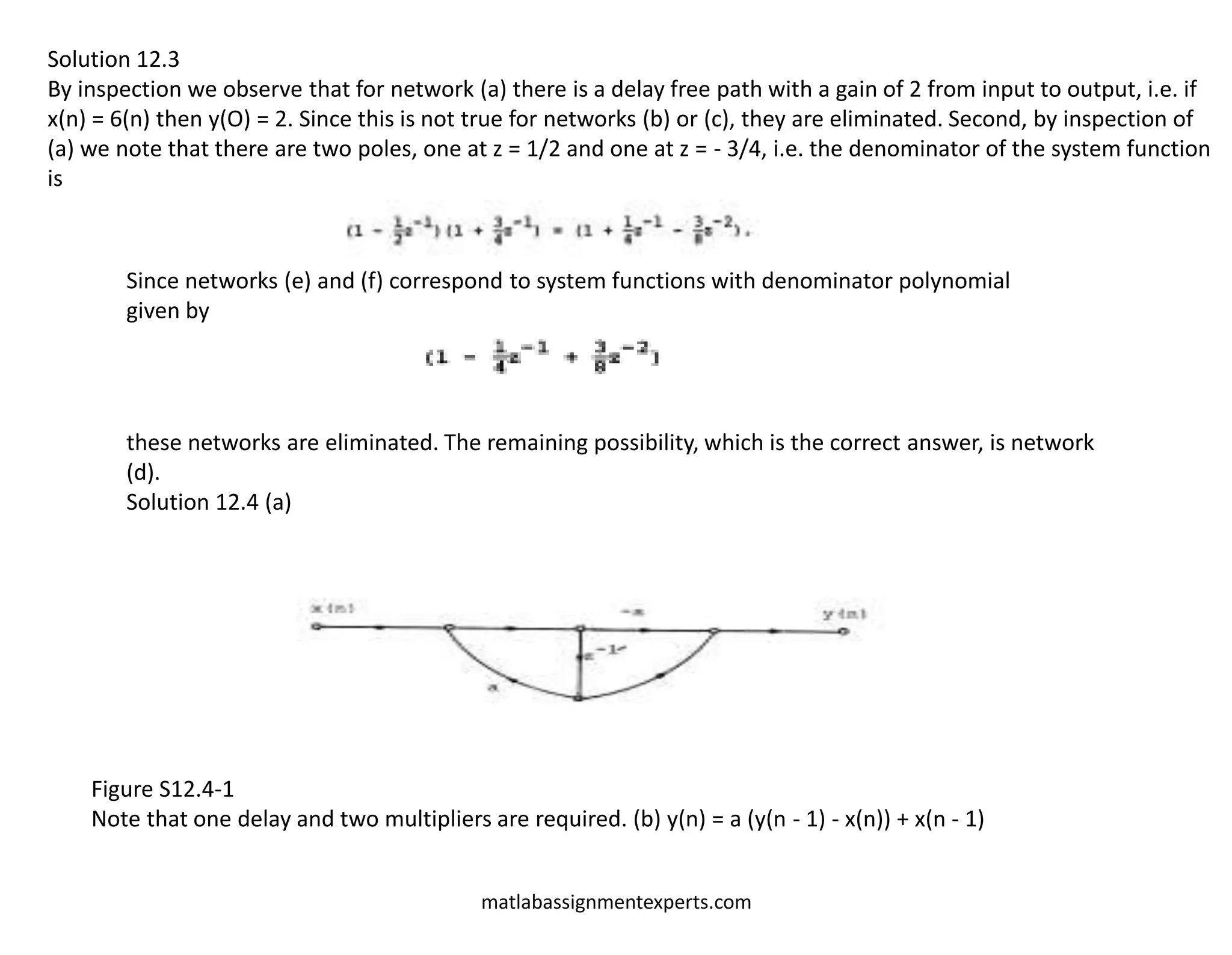
(a) Draw a network realization of this system in direct II form; and indicate in particular the number of delay branches
required and the number of branches requiring multiplication by other than +1 or -1.
(b) An alternative implementation is suggested by noting that the difference equation of the allpass system can be
expressed as
y(n) - ay(n - 1) = x(n - 1) - a x(n)
or equivalently,
y(n)=a [y(n - 1) - x(n)] + x(n - 1)
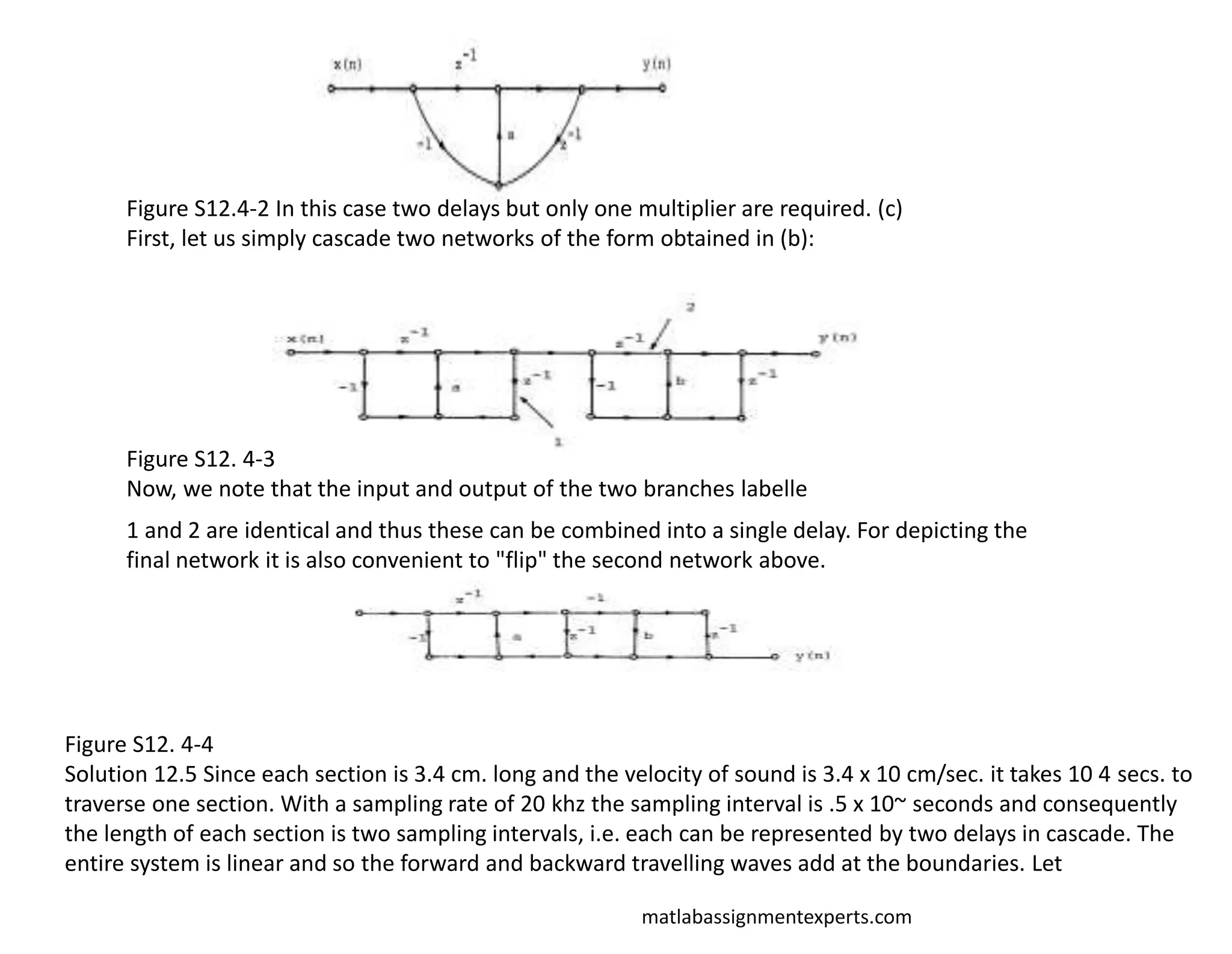
Draw a network realization of this equation requiring two delay branches but only one branch with a multiplication by
other than +1 or -1.
The primary disadvantage to the network in (b) as compared to that in
(a) is that two delay brances are required. In some applications, however, it is necessary to implement a cascade of
allpass sections. For N allpass sections it is possible to utilize a realization of each in the form determined in part
(b) but using only (N + 1) delay branches. This is accomplished essentially by sharing a delay between sections.
(c) Consider the allpass system with transfer functions
Draw a network realization of this system by "cascading" two networks of the form obtained in part (b) in such a way
that only three delay branches are required.
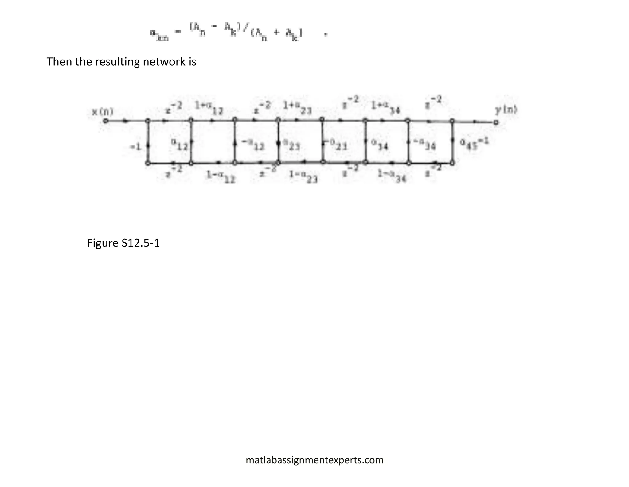
Problem 12.5
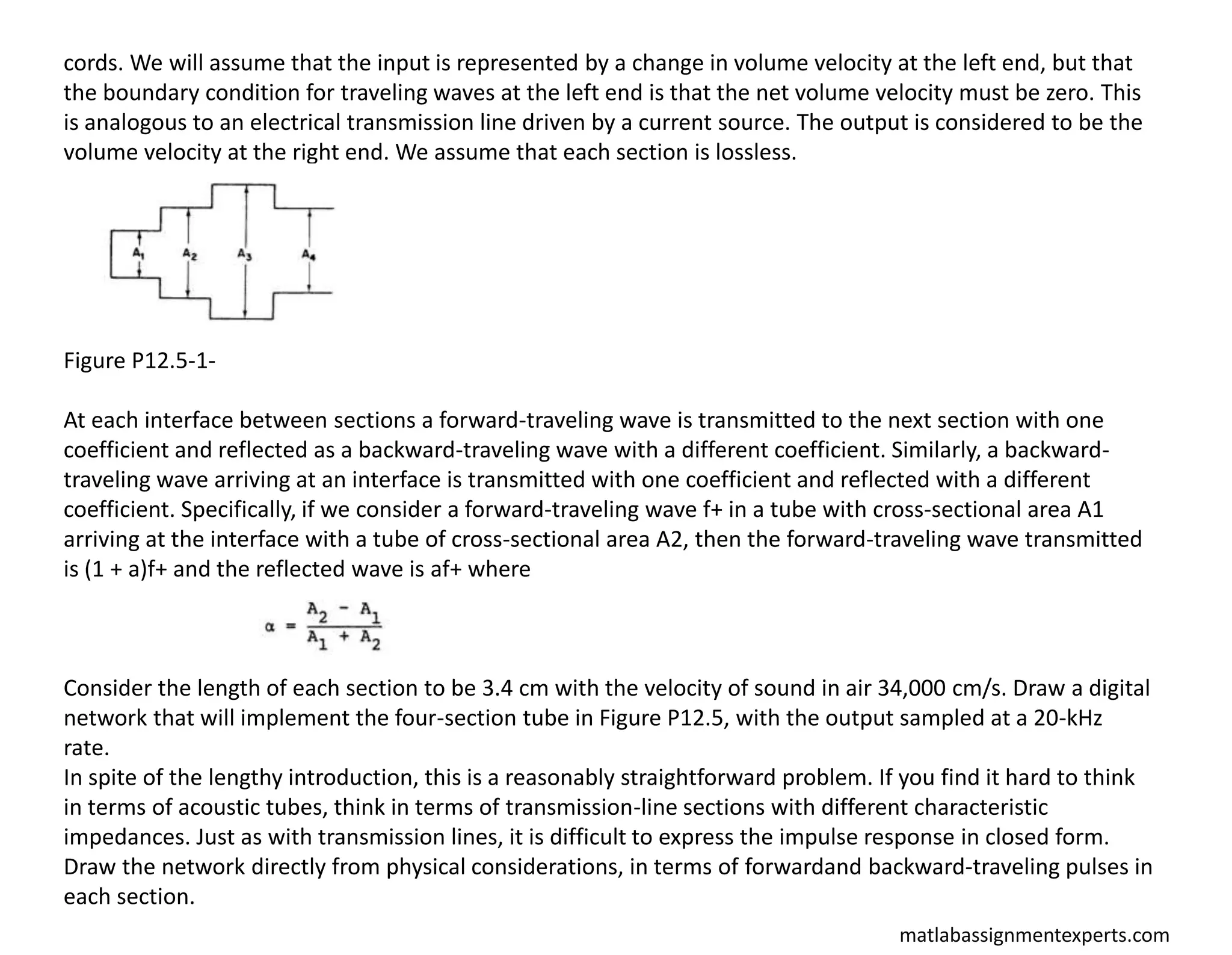
Speech production can be modeled as a linear system representing the vocal cavity, excited by puffs of air released
through the vocal cords. In synthesizing speech on a digital computer, one approach is to represent the vocal cavity
as a connection of cylindrical acoustic tubes with equal length but with different cross-sectional areas, as depicted
in Figure 12.5-1. Let us assume that we want to simulate this system in terms of the volume velocity representing air
flow. The input is coupled into the vocal tract through a small constriction, the vocal](https://image.slidesharecdn.com/matlabassignmentexperts-211108073352/75/Digital-Signal-Processing-Homework-Help-4-2048.jpg)

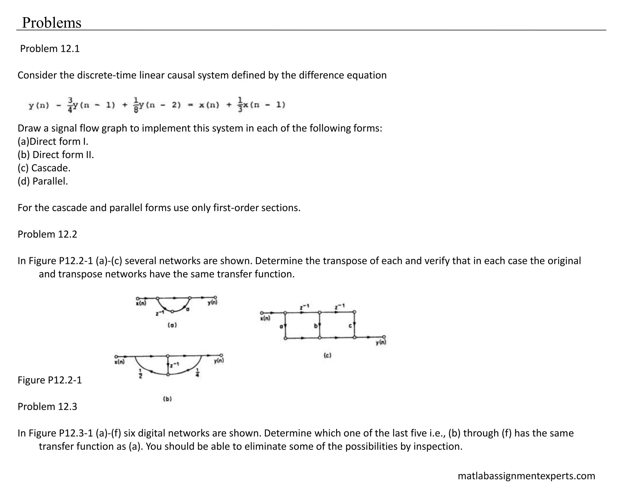
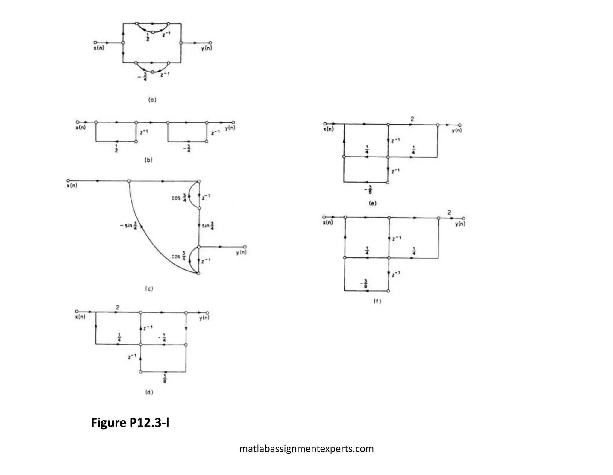
The document discusses various problems related to discrete-time linear causal systems using MATLAB. Key topics include different forms of implementing signal flow graphs, determining transposes of networks, and synthesizing speech using a digital network representation of the vocal cavity. It provides detailed instructions for drawing network realizations, analyzing transfer functions, and constructing cascades of all-pass sections.


![Reduction of multiple subsystem [compatibility mode]](https://cdn.slidesharecdn.com/ss_thumbnails/reductionofmultiplesubsystemcompatibilitymode-110418075355-phpapp01-thumbnail.jpg?width=640&height=640&fit=bounds)