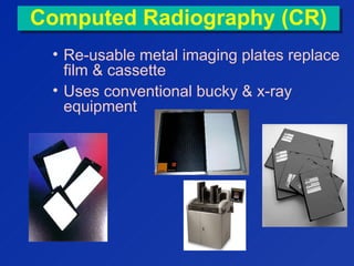
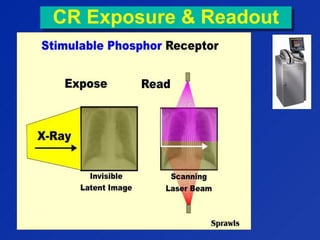
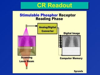
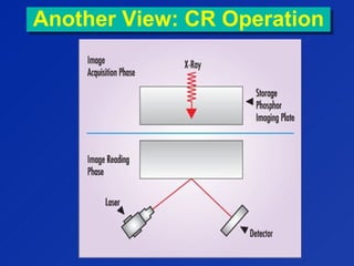
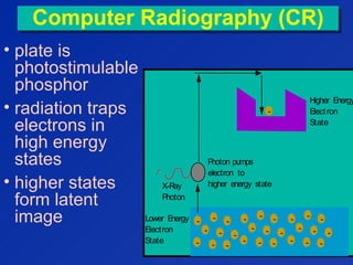
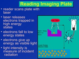
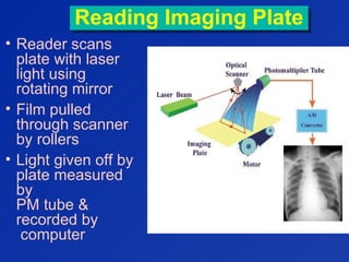
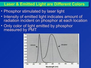
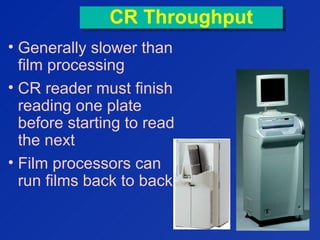
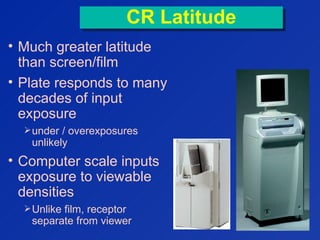
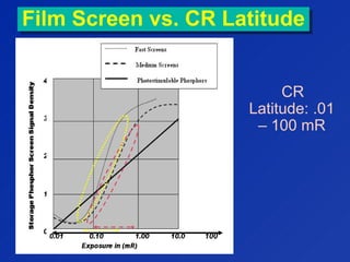
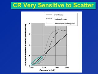
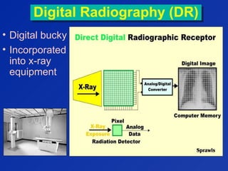
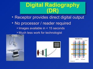
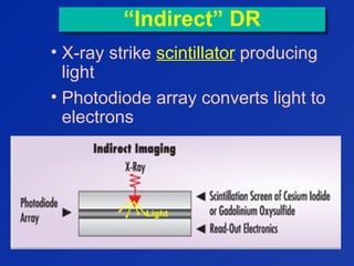
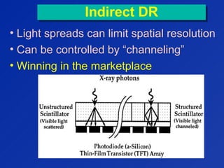
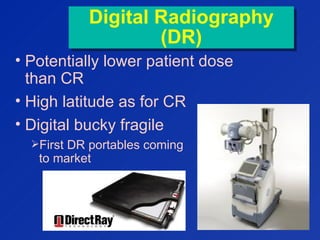
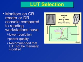
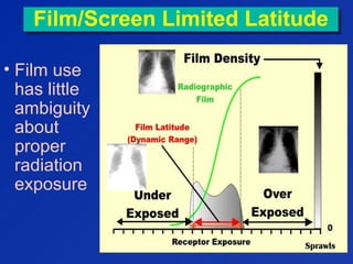
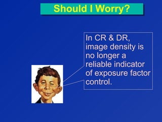
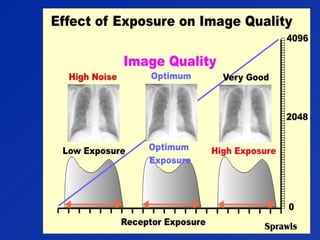
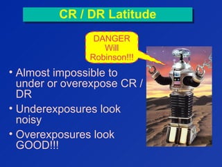
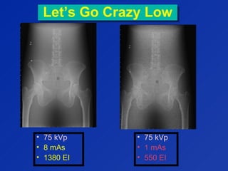
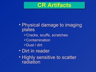
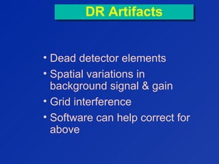
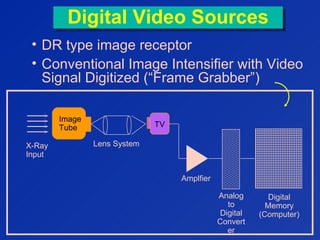
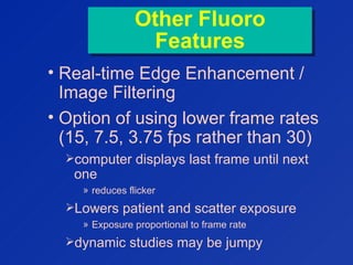
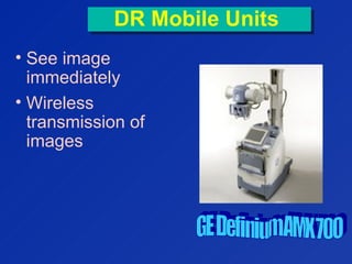
George David
Associate Professor of Radiology
Medical College of Georgia
Computed Radiography (CR)Computed Radiography (CR)
• Re-usable metal imaging plates replace
film & cassette
• Uses conventional bucky & x-ray
equipment
                                                                 
CR Exposure & ReadoutCR Exposure & Readout
CR ReadoutCR Readout
Another View: CR OperationAnother View: CR Operation
Computer Radiography (CR)Computer Radiography (CR)
• plate is
photostimulable
phosphor
• radiation traps
electrons in
high energy
states
• higher states
form latent
image
Higher Energy
Electron
State
Lower Energy
Electron
State
-
-
-
-
-
-
-
-
-
-
-
-
-
-
-
-
-
-
-
-
-
-
-
-
-
-
-
X-Ray
Photon
-
Photon pumps
electron to
higher energy state
Reading Imaging PlateReading Imaging Plate
• reader scans plate with
laser
• laser releases
electrons trapped in
high energy
states
• electrons fall to low
energy states
• electrons give up
energy as visible light
• light intensity is
measure of incident
radiation
Laser Beam
Higher Energy
Elect ron
St at e
Lower Energy
Elect ron
St at e
-
-
-
-
-
-
-
-
-
-
-
-
-
-
-
-
-
-
-
-
-
-
-
-
-
-
-
-
Lower Energy
Electron State
Reading Imaging PlateReading Imaging Plate
• Reader scans
plate with laser
light using
rotating mirror
• Film pulled
through scanner
by rollers
• Light given off by
plate measured
by
PM tube &
recorded by
computer
Laser & Emitted Light are Different ColorsLaser & Emitted Light are Different Colors
• Phosphor stimulated by laser light
• Intensity of emitted light indicates amount of
radiation incident on phosphor at each location
• Only color of light emitted by phosphor
measured by PMT
CR OperationCR Operation
• after read-out, plate erased
using a bright light
• plate can be erased virtually
without limit
• Plate life defined not by erasure
cycles but by physical wear
CR Phosphor LayerCR Phosphor Layer
• Phosphor balanced for
x-ray absorption characteristics
light output
laser light scatter
screen thickness
• Above variables affect
electronic noise
image resolution properties
speed of imaging system
• Overcoat protects plate from
physical damage
CR ResolutionCR Resolution
• Small cassettes have better
spatial resolution
Smaller pixels
More pixels / mm
CR ThroughputCR Throughput
• Generally slower than
film processing
• CR reader must finish
reading one plate
before starting to read
the next
• Film processors can
run films back to back


CR LatitudeCR Latitude
• Much greater latitude
than screen/film
• Plate responds to many
decades of input
exposure
under / overexposures
unlikely
• Computer scale inputs
exposure to viewable
densities
Unlike film, receptor
separate from viewer


Film Screen vs. CR LatitudeFilm Screen vs. CR Latitude
CR
Latitude: .01
– 100 mR
100
CR Very Sensitive to ScatterCR Very Sensitive to Scatter
Digital Radiography (DR)Digital Radiography (DR)
• Digital bucky
• Incorporated
into x-ray
equipment
Digital Radiography
(DR)
Digital Radiography
(DR)
• Receptor provides direct digital output
• No processor / reader required
Images available in < 15 seconds
Much less work for technologist
Direct vs. IndirectDirect vs. Indirect
TFT = THIN-FILM TRANSISTOR ARRAY
“Direct” DR“Direct” DR
• X-ray energy
converted directly
to electrical signal
• X-rays interact
with
semiconductor
material
Amorphous selenium
• X-rays converted
directly into
electrical charge
No intermediate
steps
“Indirect” DR“Indirect” DR
• X-ray strike scintillator producing
light
• Photodiode array converts light to
electrons
Light
Indirect DRIndirect DR
• Light spreads can limit spatial resolution
• Can be controlled by “channeling”
• Winning in the marketplace
Digital Radiography
(DR)
Digital Radiography
(DR)
• Potentially lower patient dose
than CR
• High latitude as for CR
• Digital bucky fragile
First DR portables coming
to market
SummarySummary
• DR becoming industry leader in
radiographic imaging
• DR images displayed & stored in
about 8 seconds
• DR has faster throughput
Up to 2-4 times faster than traditional
screen-film-darkroom technology
Raw Data ImageRaw Data Image
• Unprocessed image as read from
receptor
CR
» Intensity data from PMT’s as a result of scanning
plate with laser
DR
» Raw Data read directly from TFT array
• Not a readable diagnostic image
• Requires computer post-
processing
Specific software algorithms must be
applied to image prior to presenting it as
finished radiograph
Enhancing Raw Image
(Image Segmentation)
Enhancing Raw Image
(Image Segmentation)
1. Identify collimated image
border
2. Separate raw radiation
from anatomy
3. Apply appropriate tone-
scale to image
 Done with look-up table (LUTLUT)
This process is
specific to a
particular body
part and
projection
*
Look Up Table (LUT)Look Up Table (LUT)
• Converts a raw
data pixel value to
a processed pixel
value
• “Original” raw
data pixel value
indicates amount
of radiation falling
on pixel
Image SegmentationImage Segmentation
• Computer must establish
location of collimated border of
image
• Computer then defines
anatomic region
• Finished image produced by
tone scaling
Requires histogram analysis of
anatomic region
HistogramHistogram
• Graph
showing how
much of
image is
exposed at
various levels
Tone Scaling
Post-Processing
Tone Scaling
Post-Processing
• Body part & projection-specific
algorithms determine average
exposure
Must correctly identify anatomical region
• LUT computed to display image with
proper
Density
Contrast
LUT can Simulate
Appearance of Film
LUT can Simulate
Appearance of Film
LUT SelectionLUT Selection
• LUT
calculated
by algorithm
depends on
Body part
projection
• User can
also alter
LUT
manually
LUT SelectionLUT Selection
• Monitors on CR
reader or DR
console compared
to reading
workstations have
lower resolution
poorer quality
Recommended that
LUT not be manually
modified
Film/Screen Limited LatitudeFilm/Screen Limited Latitude
• Film use
has little
ambiguity
about
proper
radiation
exposure
Should I Worry?Should I Worry?
In CR & DR,
image density is
no longer a
reliable indicator
of exposure factor
control.
• Almost impossible to
under or overexpose CR /
DR
• Underexposures look
noisy
• Overexposures look
GOOD!!!
CR / DR LatitudeCR / DR Latitude
DANGER
Will
Robinson!!!
Exposure CreepExposure Creep:
Tendency of radiographs toward
higher-then-necessary exposures
Exposure CreepExposure Creep:
Tendency of radiographs toward
higher-then-necessary exposures
• No detrimental effect on image quality
• Desire to see less noise on radiographs
• Increased exposure latitude
• No one complains
So how do I know if exposure is
optimum by looking at my image?
So how do I know if exposure is
optimum by looking at my image?
Exposure IndexExposure Index
• Each manufacturer provides feedback to
technologist on exposure to digital
receptor
• Displayed on CR reader monitor
• Displayed on workstations
Exposure IndexExposure Index
• Measure of radiation received by receptor
below anatomy
• Not a direct measure of patient exposure
• If exposure index higher than
recommended range, patient
overexposed
Exposure Indication Varies
between Manufacturers
Exposure Indication Varies
between Manufacturers
Receptor
Exposure
Kodak
EI
Fuji S
Number
0.5 1700 400
1 2000 200
2 2300 100
4 2600 50
Fuji
“S” number goes down
as exposure goes up!
S is half when
exposure doubled
Kodak
Logarithmic scale
EI goes up 300 when
exposure doubled
Exposure IndexExposure Index
• Technologist should strive to keep
exposure index consistent
• Kodak recommendation for exposure
index
1800 – 2200
• George’s recommendation
“Maximum tolerable noise”
As low as possible while providing
tolerable noise
This is not a beauty contest!
Calculated Exposure
Index Affected by
Calculated Exposure
Index Affected by
• X-Ray technique selection
• Improper centering of image on
cassette
• Improper selection of study or
projection
• Placing two or more views on
same cassette
Can cause image to appear dark
Phototimed Phantom ImagePhototimed Phantom Image
• 75 kVp
• 88 mAs
• 2460 EI
Let’s Approximately Double mAsLet’s Approximately Double mAs
• 75 kVp
• 88 mAs
• 2460 EI
• 75 kVp
• 160 mAs
• 2680 EI
Let’s Go CrazyLet’s Go Crazy
• 75 kVp
• 88 mAs
• 2460 EI
• 75 kVp
• 640 mAs
• 3300 EI
How Low Can You Go? Cut mAs in Half!How Low Can You Go? Cut mAs in Half!
• 75 kVp
• 88 mAs
• 2460 EI
• 75 kVp
• 40 mAs
• 2060 EI
Let’s Go Crazy LowLet’s Go Crazy Low
• 75 kVp
• 8 mAs
• 1380 EI
• 75 kVp
• 1 mAs
• 550 EI
CR ArtifactsCR Artifacts
• Physical damage to imaging
plates
Cracks, scuffs, scratches
Contamination
Dust / dirt
• Dirt in reader
• Highly sensitive to scatter
radiation
CR Grid InterferenceCR Grid Interference
• 103 lines / inch grids have same frequency
as CR laser scanner. This can cause
“Moire” pattern artifact
• Align grid lines perpendicular to scan
orientation whenever possible
Reduces chances of artifacts caused by laser scanner.
DR ArtifactsDR Artifacts
• Dead detector elements
• Spatial variations in
background signal & gain
• Grid interference
• Software can help correct for
above
Shifting Gears:
Fluoroscopy Issues
Shifting Gears:
Fluoroscopy Issues
Digital Video SourcesDigital Video Sources
• DR type image receptor
• Conventional Image Intensifier with Video
Signal Digitized (“Frame Grabber”)
I
m
a
g
e
T
u
b
e
X-Ray
Input
Image
Tube TV
Amplfier
Analog
to
Digital
Convert
er
Digital
Memory
(Computer)
Lens System
Digital Spot FilmDigital Spot Film
• Frame grabber digitizes image
• Digital image saved by computer
• Radiographic Technique used
 required to control quantum noise
Last Image HoldLast Image Hold
• Computer displays last fluoro image
before radiation shut off.
• Image noisier than for digital spot
Image made at fluoroscopic technique / intensity
• Allows operator to review static
processes without keeping beam on
ideal for teaching environments
ideal for orthopedic applications such as hip
pinning
• Less radiation than digital spot
Fluoro Frame
Averaging
Fluoro Frame
Averaging
• Conventional fluoro only displays
current frame
• Frame averaging allows computer
to average current with user-
selectable number of previous
frames
Averages current frame & history
Fluoro Frame
Averaging Tradeoff
Fluoro Frame
Averaging Tradeoff
• Advantage:
Reduces quantum noise
• Disadvantage
Because history frames are averaged with
current frame, any motion can result in lag
Other Fluoro
Features
Other Fluoro
Features
• Real-time Edge Enhancement /
Image Filtering
• Option of using lower frame rates
(15, 7.5, 3.75 fps rather than 30)
computer displays last frame until next
one
» reduces flicker
Lowers patient and scatter exposure
» Exposure proportional to frame rate
dynamic studies may be jumpy
The Future of DigitalThe Future of Digital
DR Mobile UnitsDR Mobile Units
• See image
immediately
• Wireless
transmission of
images
Other PossibilitiesOther Possibilities
• Tomosynthesis
Multi-slice linear tomography from
one exposure series
• Histogram Equalization
Use computer to provide
approximately equal density to
various areas of image.
DR & Energy SubtractionDR & Energy Subtraction
• 2 images taken milliseconds
apart at 2 different kVp’s
• Combine / subtract images
Soft Tissue Image Bone Image
The EndThe End
?

compiter radiography and digital radiography

  • 1.
    George David Associate Professorof Radiology Medical College of Georgia
  • 2.
    Computed Radiography (CR)ComputedRadiography (CR) • Re-usable metal imaging plates replace film & cassette • Uses conventional bucky & x-ray equipment                                                                  
  • 3.
    CR Exposure &ReadoutCR Exposure & Readout
  • 4.
  • 5.
    Another View: CROperationAnother View: CR Operation
  • 6.
    Computer Radiography (CR)ComputerRadiography (CR) • plate is photostimulable phosphor • radiation traps electrons in high energy states • higher states form latent image Higher Energy Electron State Lower Energy Electron State - - - - - - - - - - - - - - - - - - - - - - - - - - - X-Ray Photon - Photon pumps electron to higher energy state
  • 7.
    Reading Imaging PlateReadingImaging Plate • reader scans plate with laser • laser releases electrons trapped in high energy states • electrons fall to low energy states • electrons give up energy as visible light • light intensity is measure of incident radiation Laser Beam Higher Energy Elect ron St at e Lower Energy Elect ron St at e - - - - - - - - - - - - - - - - - - - - - - - - - - - - Lower Energy Electron State
  • 8.
    Reading Imaging PlateReadingImaging Plate • Reader scans plate with laser light using rotating mirror • Film pulled through scanner by rollers • Light given off by plate measured by PM tube & recorded by computer
  • 9.
    Laser & EmittedLight are Different ColorsLaser & Emitted Light are Different Colors • Phosphor stimulated by laser light • Intensity of emitted light indicates amount of radiation incident on phosphor at each location • Only color of light emitted by phosphor measured by PMT
  • 10.
    CR OperationCR Operation •after read-out, plate erased using a bright light • plate can be erased virtually without limit • Plate life defined not by erasure cycles but by physical wear
  • 11.
    CR Phosphor LayerCRPhosphor Layer • Phosphor balanced for x-ray absorption characteristics light output laser light scatter screen thickness • Above variables affect electronic noise image resolution properties speed of imaging system • Overcoat protects plate from physical damage
  • 12.
    CR ResolutionCR Resolution •Small cassettes have better spatial resolution Smaller pixels More pixels / mm
  • 13.
    CR ThroughputCR Throughput •Generally slower than film processing • CR reader must finish reading one plate before starting to read the next • Film processors can run films back to back                      
  • 14.
    CR LatitudeCR Latitude •Much greater latitude than screen/film • Plate responds to many decades of input exposure under / overexposures unlikely • Computer scale inputs exposure to viewable densities Unlike film, receptor separate from viewer                      
  • 15.
    Film Screen vs.CR LatitudeFilm Screen vs. CR Latitude CR Latitude: .01 – 100 mR 100
  • 16.
    CR Very Sensitiveto ScatterCR Very Sensitive to Scatter
  • 17.
    Digital Radiography (DR)DigitalRadiography (DR) • Digital bucky • Incorporated into x-ray equipment
  • 18.
    Digital Radiography (DR) Digital Radiography (DR) •Receptor provides direct digital output • No processor / reader required Images available in < 15 seconds Much less work for technologist
  • 19.
    Direct vs. IndirectDirectvs. Indirect TFT = THIN-FILM TRANSISTOR ARRAY
  • 20.
    “Direct” DR“Direct” DR •X-ray energy converted directly to electrical signal • X-rays interact with semiconductor material Amorphous selenium • X-rays converted directly into electrical charge No intermediate steps
  • 21.
    “Indirect” DR“Indirect” DR •X-ray strike scintillator producing light • Photodiode array converts light to electrons Light
  • 22.
    Indirect DRIndirect DR •Light spreads can limit spatial resolution • Can be controlled by “channeling” • Winning in the marketplace
  • 23.
    Digital Radiography (DR) Digital Radiography (DR) •Potentially lower patient dose than CR • High latitude as for CR • Digital bucky fragile First DR portables coming to market
  • 24.
    SummarySummary • DR becomingindustry leader in radiographic imaging • DR images displayed & stored in about 8 seconds • DR has faster throughput Up to 2-4 times faster than traditional screen-film-darkroom technology
  • 25.
    Raw Data ImageRawData Image • Unprocessed image as read from receptor CR » Intensity data from PMT’s as a result of scanning plate with laser DR » Raw Data read directly from TFT array • Not a readable diagnostic image • Requires computer post- processing Specific software algorithms must be applied to image prior to presenting it as finished radiograph
  • 26.
    Enhancing Raw Image (ImageSegmentation) Enhancing Raw Image (Image Segmentation) 1. Identify collimated image border 2. Separate raw radiation from anatomy 3. Apply appropriate tone- scale to image  Done with look-up table (LUTLUT) This process is specific to a particular body part and projection *
  • 27.
    Look Up Table(LUT)Look Up Table (LUT) • Converts a raw data pixel value to a processed pixel value • “Original” raw data pixel value indicates amount of radiation falling on pixel
  • 28.
    Image SegmentationImage Segmentation •Computer must establish location of collimated border of image • Computer then defines anatomic region • Finished image produced by tone scaling Requires histogram analysis of anatomic region
  • 29.
    HistogramHistogram • Graph showing how muchof image is exposed at various levels
  • 30.
    Tone Scaling Post-Processing Tone Scaling Post-Processing •Body part & projection-specific algorithms determine average exposure Must correctly identify anatomical region • LUT computed to display image with proper Density Contrast
  • 31.
    LUT can Simulate Appearanceof Film LUT can Simulate Appearance of Film
  • 32.
    LUT SelectionLUT Selection •LUT calculated by algorithm depends on Body part projection • User can also alter LUT manually
  • 33.
    LUT SelectionLUT Selection •Monitors on CR reader or DR console compared to reading workstations have lower resolution poorer quality Recommended that LUT not be manually modified
  • 34.
    Film/Screen Limited LatitudeFilm/ScreenLimited Latitude • Film use has little ambiguity about proper radiation exposure
  • 35.
    Should I Worry?ShouldI Worry? In CR & DR, image density is no longer a reliable indicator of exposure factor control.
  • 37.
    • Almost impossibleto under or overexpose CR / DR • Underexposures look noisy • Overexposures look GOOD!!! CR / DR LatitudeCR / DR Latitude DANGER Will Robinson!!!
  • 38.
    Exposure CreepExposure Creep: Tendencyof radiographs toward higher-then-necessary exposures Exposure CreepExposure Creep: Tendency of radiographs toward higher-then-necessary exposures • No detrimental effect on image quality • Desire to see less noise on radiographs • Increased exposure latitude • No one complains
  • 39.
    So how doI know if exposure is optimum by looking at my image? So how do I know if exposure is optimum by looking at my image?
  • 41.
    Exposure IndexExposure Index •Each manufacturer provides feedback to technologist on exposure to digital receptor • Displayed on CR reader monitor • Displayed on workstations
  • 42.
    Exposure IndexExposure Index •Measure of radiation received by receptor below anatomy • Not a direct measure of patient exposure • If exposure index higher than recommended range, patient overexposed
  • 43.
    Exposure Indication Varies betweenManufacturers Exposure Indication Varies between Manufacturers Receptor Exposure Kodak EI Fuji S Number 0.5 1700 400 1 2000 200 2 2300 100 4 2600 50 Fuji “S” number goes down as exposure goes up! S is half when exposure doubled Kodak Logarithmic scale EI goes up 300 when exposure doubled
  • 44.
    Exposure IndexExposure Index •Technologist should strive to keep exposure index consistent • Kodak recommendation for exposure index 1800 – 2200 • George’s recommendation “Maximum tolerable noise” As low as possible while providing tolerable noise This is not a beauty contest!
  • 45.
    Calculated Exposure Index Affectedby Calculated Exposure Index Affected by • X-Ray technique selection • Improper centering of image on cassette • Improper selection of study or projection • Placing two or more views on same cassette Can cause image to appear dark
  • 46.
    Phototimed Phantom ImagePhototimedPhantom Image • 75 kVp • 88 mAs • 2460 EI
  • 47.
    Let’s Approximately DoublemAsLet’s Approximately Double mAs • 75 kVp • 88 mAs • 2460 EI • 75 kVp • 160 mAs • 2680 EI
  • 48.
    Let’s Go CrazyLet’sGo Crazy • 75 kVp • 88 mAs • 2460 EI • 75 kVp • 640 mAs • 3300 EI
  • 49.
    How Low CanYou Go? Cut mAs in Half!How Low Can You Go? Cut mAs in Half! • 75 kVp • 88 mAs • 2460 EI • 75 kVp • 40 mAs • 2060 EI
  • 50.
    Let’s Go CrazyLowLet’s Go Crazy Low • 75 kVp • 8 mAs • 1380 EI • 75 kVp • 1 mAs • 550 EI
  • 51.
    CR ArtifactsCR Artifacts •Physical damage to imaging plates Cracks, scuffs, scratches Contamination Dust / dirt • Dirt in reader • Highly sensitive to scatter radiation
  • 52.
    CR Grid InterferenceCRGrid Interference • 103 lines / inch grids have same frequency as CR laser scanner. This can cause “Moire” pattern artifact • Align grid lines perpendicular to scan orientation whenever possible Reduces chances of artifacts caused by laser scanner.
  • 53.
    DR ArtifactsDR Artifacts •Dead detector elements • Spatial variations in background signal & gain • Grid interference • Software can help correct for above
  • 54.
  • 55.
    Digital Video SourcesDigitalVideo Sources • DR type image receptor • Conventional Image Intensifier with Video Signal Digitized (“Frame Grabber”) I m a g e T u b e X-Ray Input Image Tube TV Amplfier Analog to Digital Convert er Digital Memory (Computer) Lens System
  • 56.
    Digital Spot FilmDigitalSpot Film • Frame grabber digitizes image • Digital image saved by computer • Radiographic Technique used  required to control quantum noise
  • 57.
    Last Image HoldLastImage Hold • Computer displays last fluoro image before radiation shut off. • Image noisier than for digital spot Image made at fluoroscopic technique / intensity • Allows operator to review static processes without keeping beam on ideal for teaching environments ideal for orthopedic applications such as hip pinning • Less radiation than digital spot
  • 58.
    Fluoro Frame Averaging Fluoro Frame Averaging •Conventional fluoro only displays current frame • Frame averaging allows computer to average current with user- selectable number of previous frames Averages current frame & history
  • 59.
    Fluoro Frame Averaging Tradeoff FluoroFrame Averaging Tradeoff • Advantage: Reduces quantum noise • Disadvantage Because history frames are averaged with current frame, any motion can result in lag
  • 60.
    Other Fluoro Features Other Fluoro Features •Real-time Edge Enhancement / Image Filtering • Option of using lower frame rates (15, 7.5, 3.75 fps rather than 30) computer displays last frame until next one » reduces flicker Lowers patient and scatter exposure » Exposure proportional to frame rate dynamic studies may be jumpy
  • 61.
    The Future ofDigitalThe Future of Digital
  • 62.
    DR Mobile UnitsDRMobile Units • See image immediately • Wireless transmission of images
  • 63.
    Other PossibilitiesOther Possibilities •Tomosynthesis Multi-slice linear tomography from one exposure series • Histogram Equalization Use computer to provide approximately equal density to various areas of image.
  • 64.
    DR & EnergySubtractionDR & Energy Subtraction • 2 images taken milliseconds apart at 2 different kVp’s • Combine / subtract images Soft Tissue Image Bone Image
  • 65.