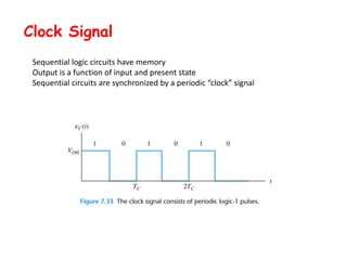
1. Sequential logic circuits have memory and their outputs depend on both their inputs and present state. They are synchronized by a periodic clock signal.
2. An SR flip-flop is a basic type of sequential circuit that can be constructed using two NOR gates. Edge-triggered flip-flops only change state when the clock signal changes.
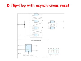
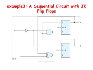
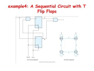
3. There are different types of flip-flops like D, JK, and T flip-flops that are used to build sequential circuits. Their behavior and output can be analyzed using state tables and state diagrams that show the unique circuit configurations and transitions between states.


![Attack surfaces and attack tress[inform]](https://cdn.slidesharecdn.com/ss_thumbnails/lecture03-260108015941-a4dee53b-thumbnail.jpg?width=640&height=640&fit=bounds)

