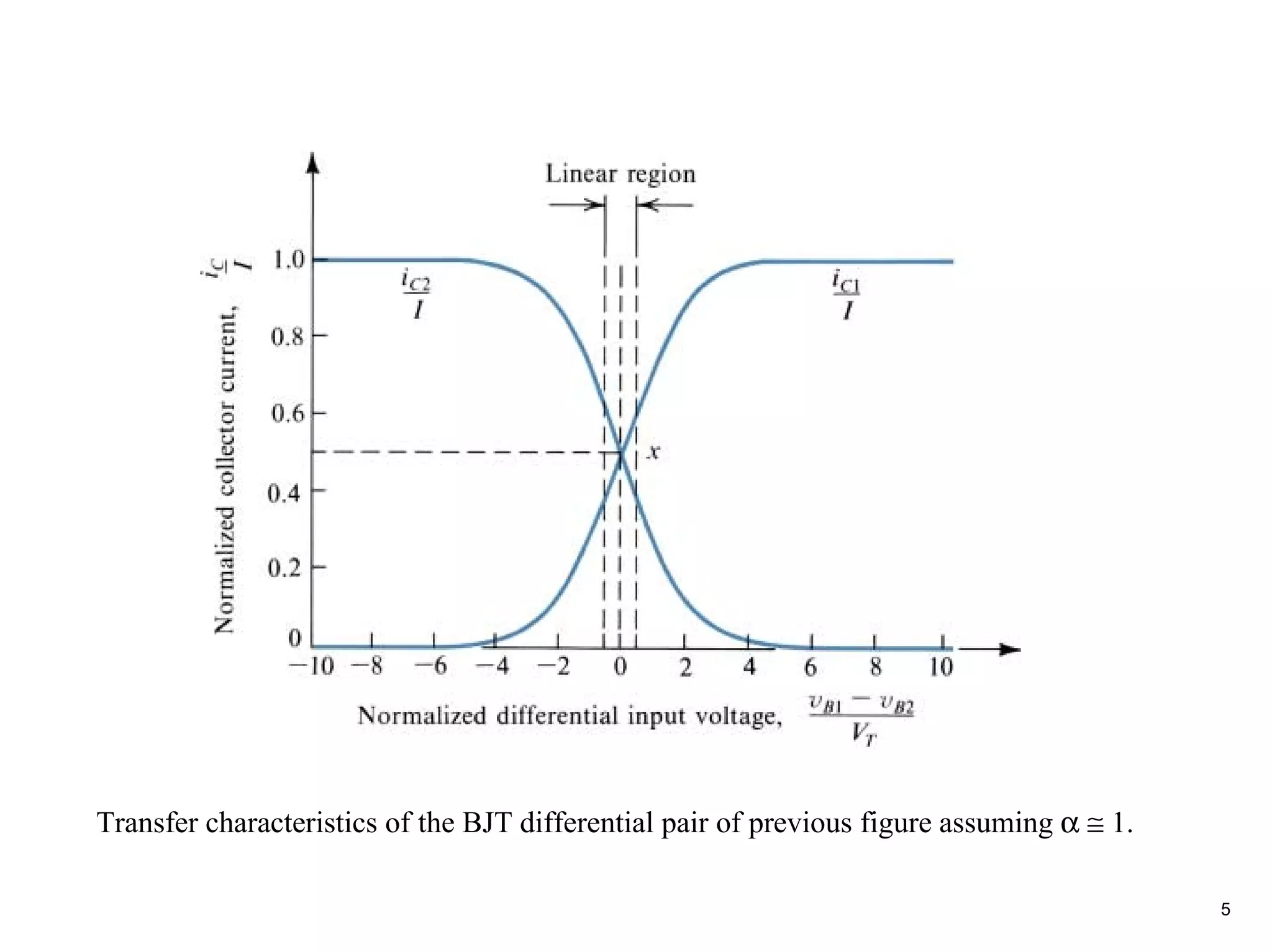
The document discusses different modes of operation and transfer characteristics of differential amplifiers. It covers various circuit implementations of differential pairs using BJTs and MOSFETs, including current mirrors, active loads, and multistage amplifiers. Analysis techniques are presented for determining signal currents and evaluating differential gain, input resistance, and frequency response.
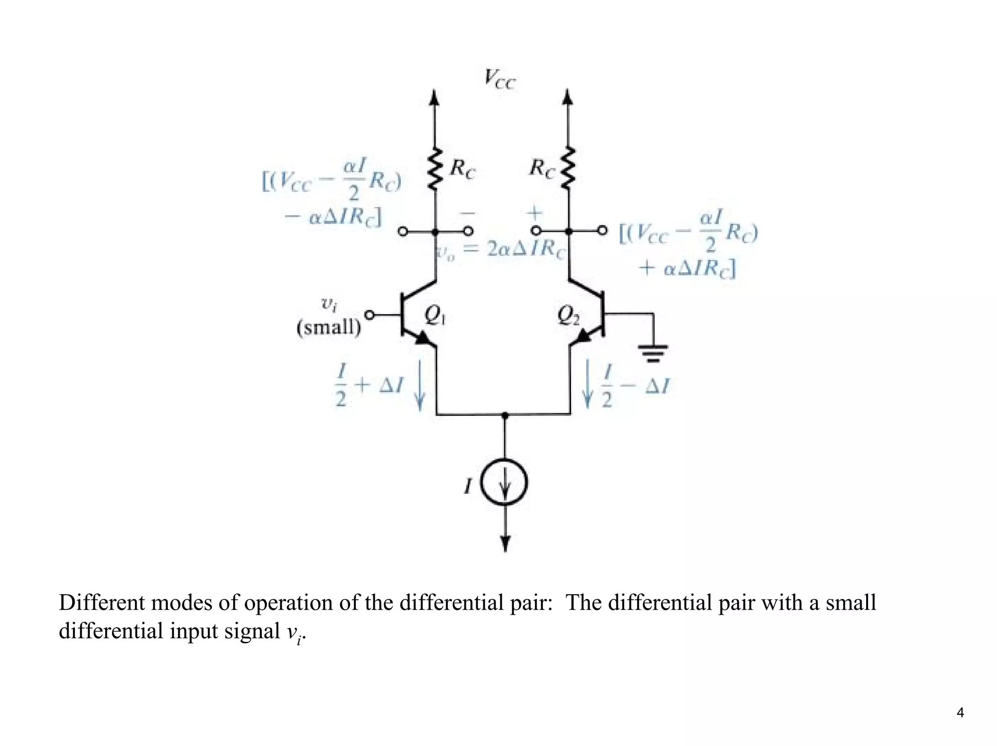
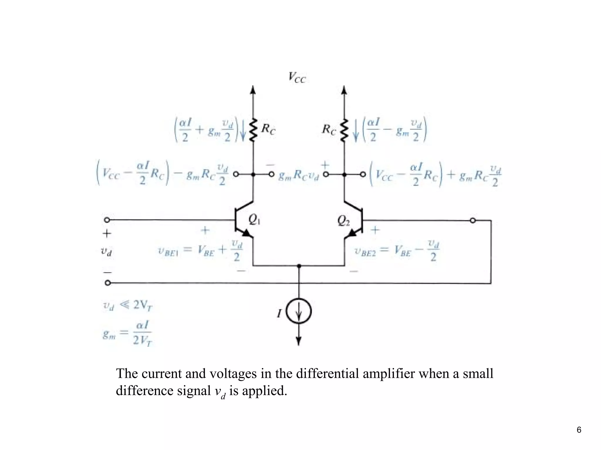
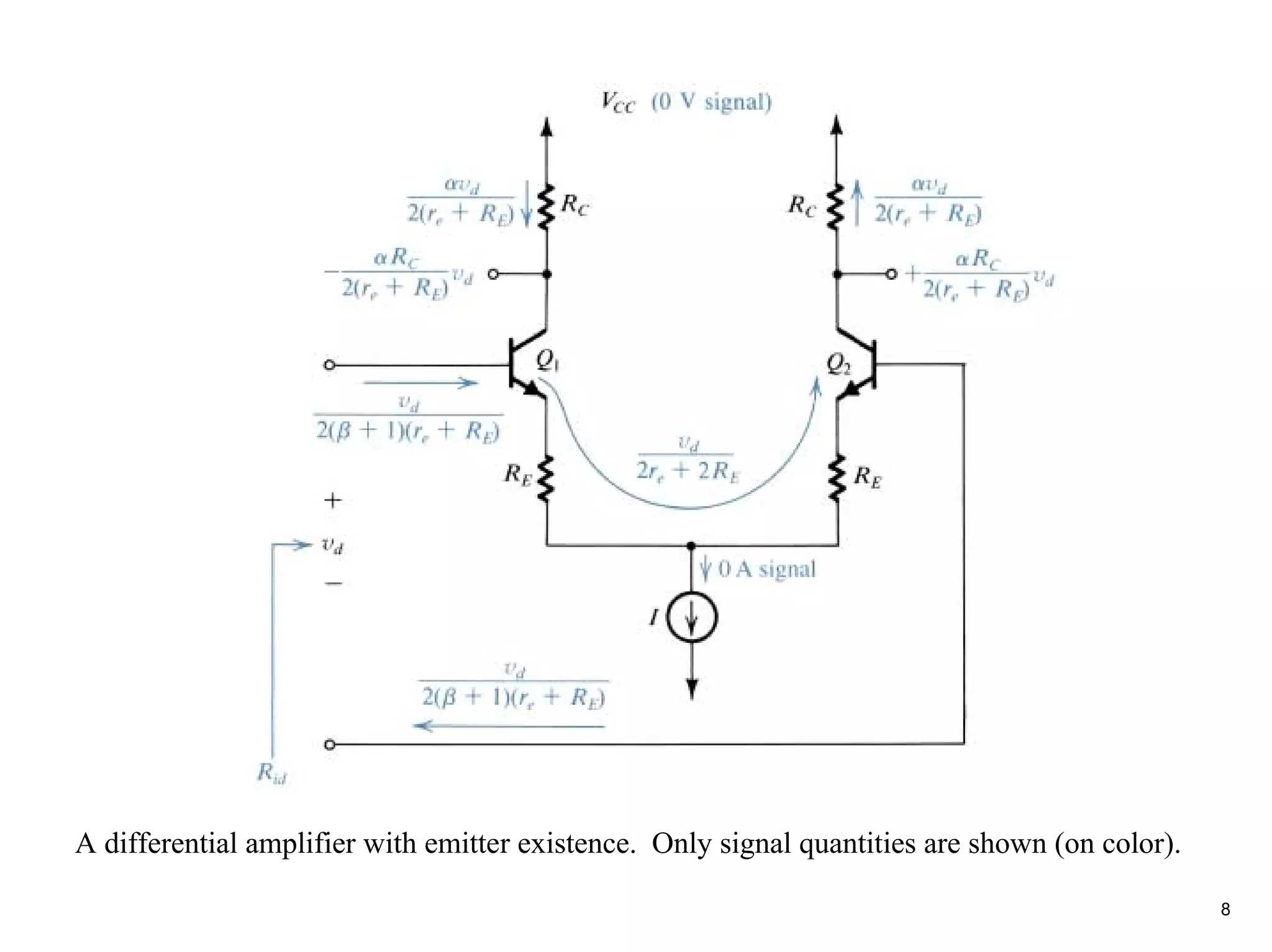
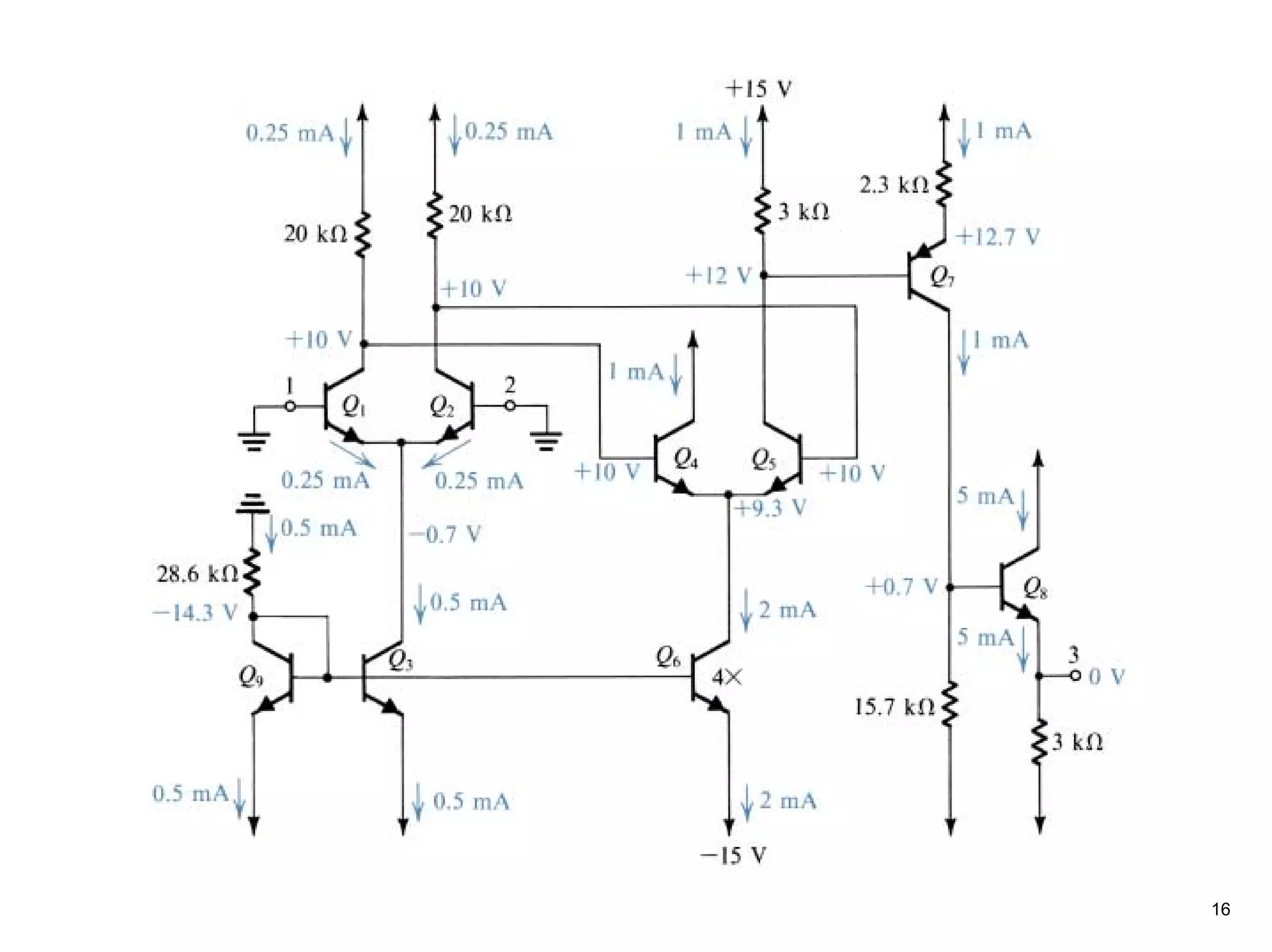
The current andvoltages in the differential amplifier when a small
difference signal vd is applied.
6
8.
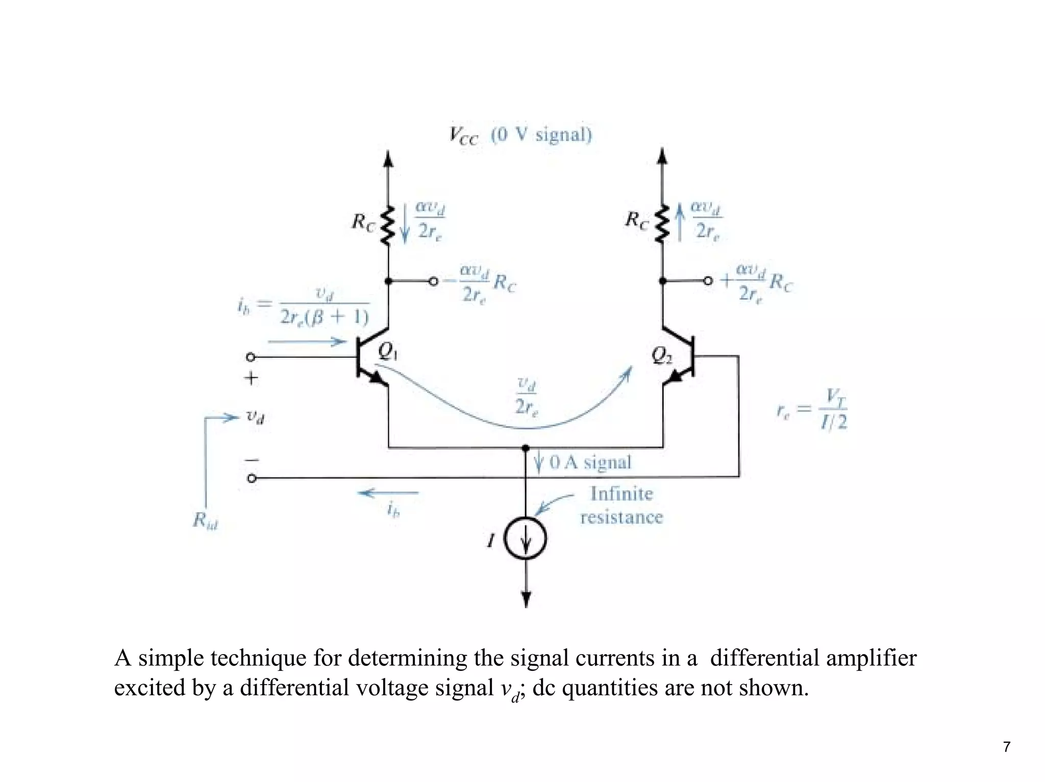
A simple techniquefor determining the signal currents in a differential amplifier
excited by a differential voltage signal vd; dc quantities are not shown.
7
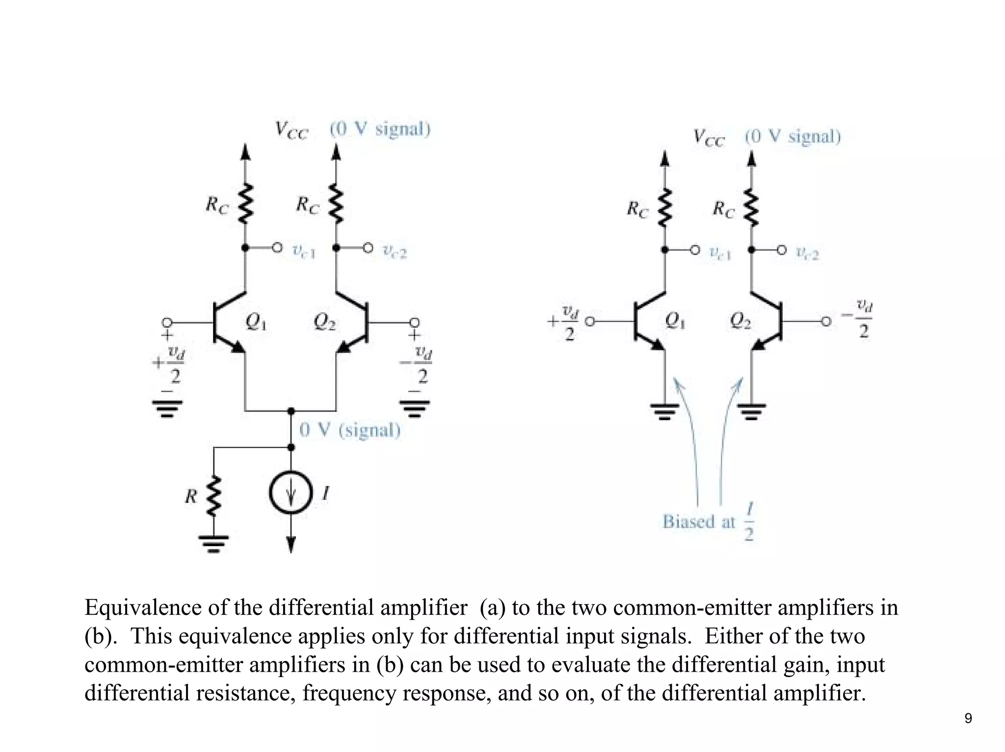
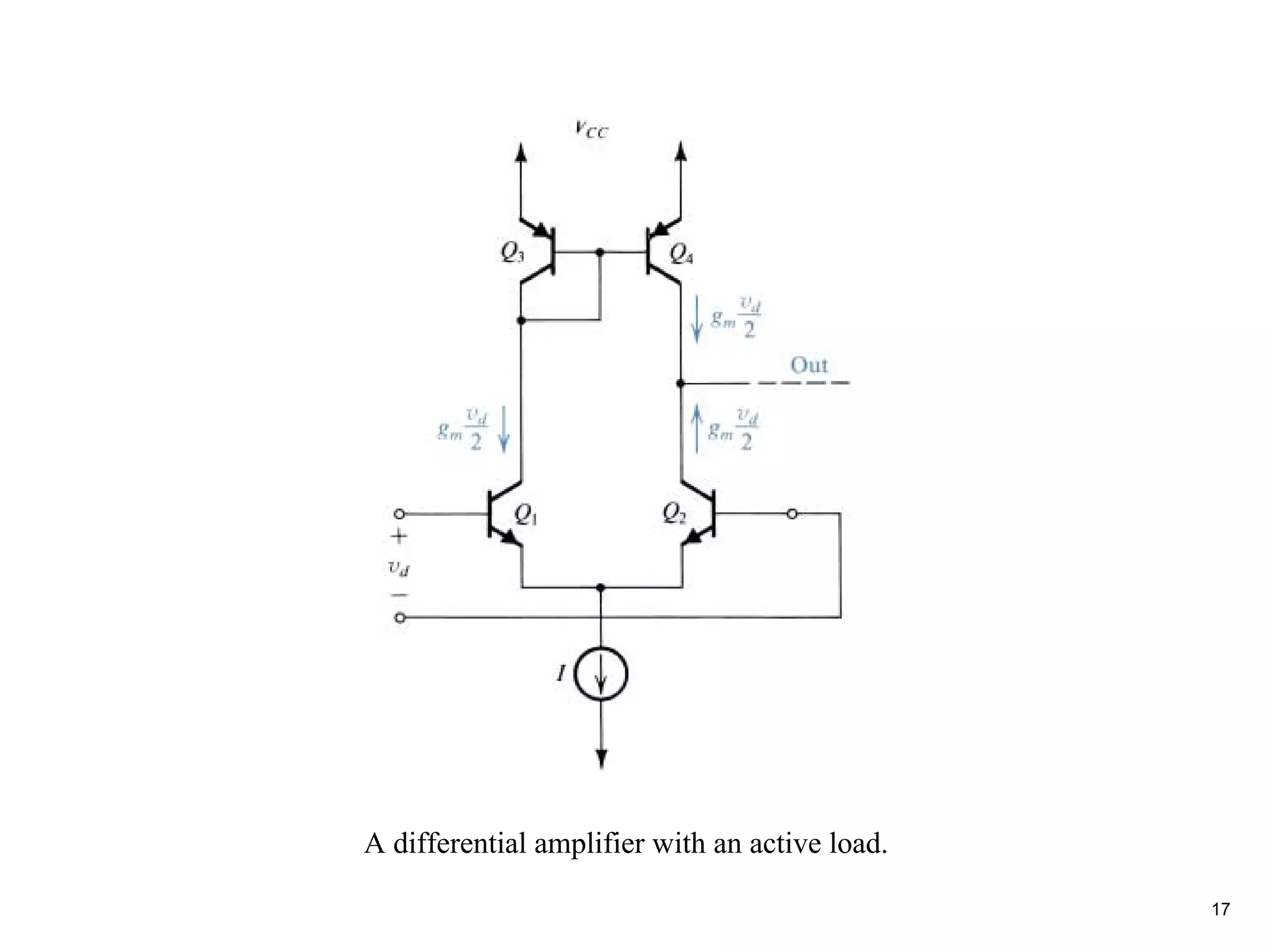
Equivalence of thedifferential amplifier (a) to the two common-emitter amplifiers in
(b). This equivalence applies only for differential input signals. Either of the two
common-emitter amplifiers in (b) can be used to evaluate the differential gain, input
differential resistance, frequency response, and so on, of the differential amplifier.
9
11.
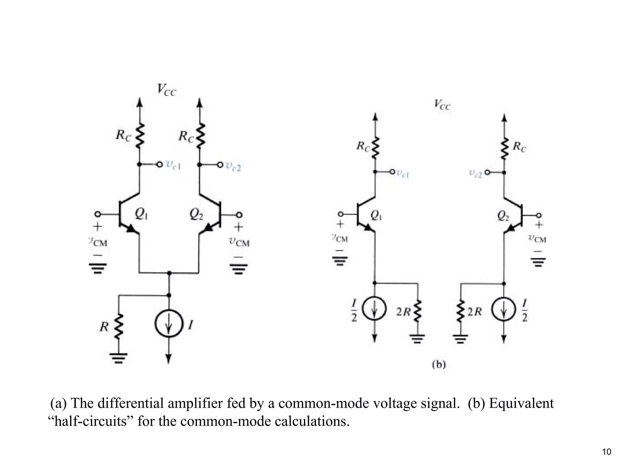
(a) The differentialamplifier fed by a common-mode voltage signal. (b) Equivalent
“half-circuits” for the common-mode calculations.
10
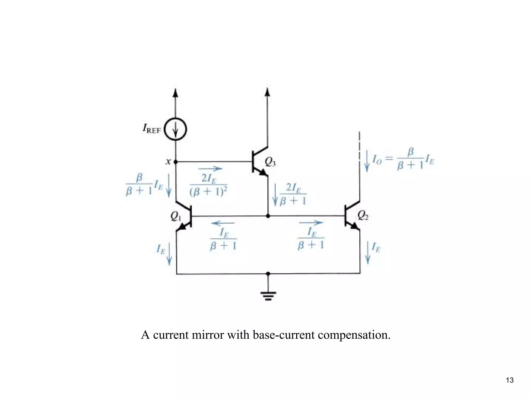
12.
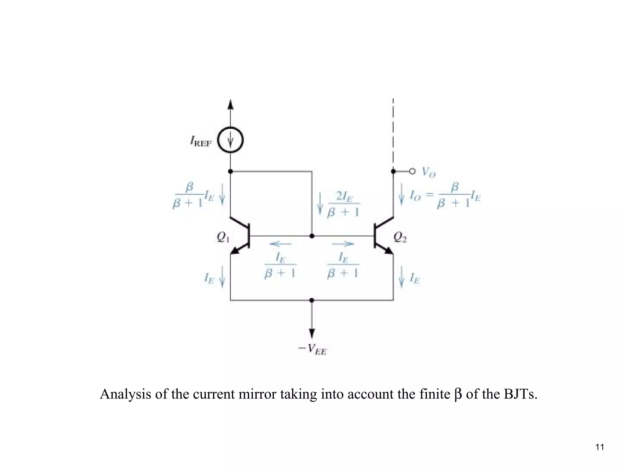
Analysis of thecurrent mirror taking into account the finite β of the BJTs.
11
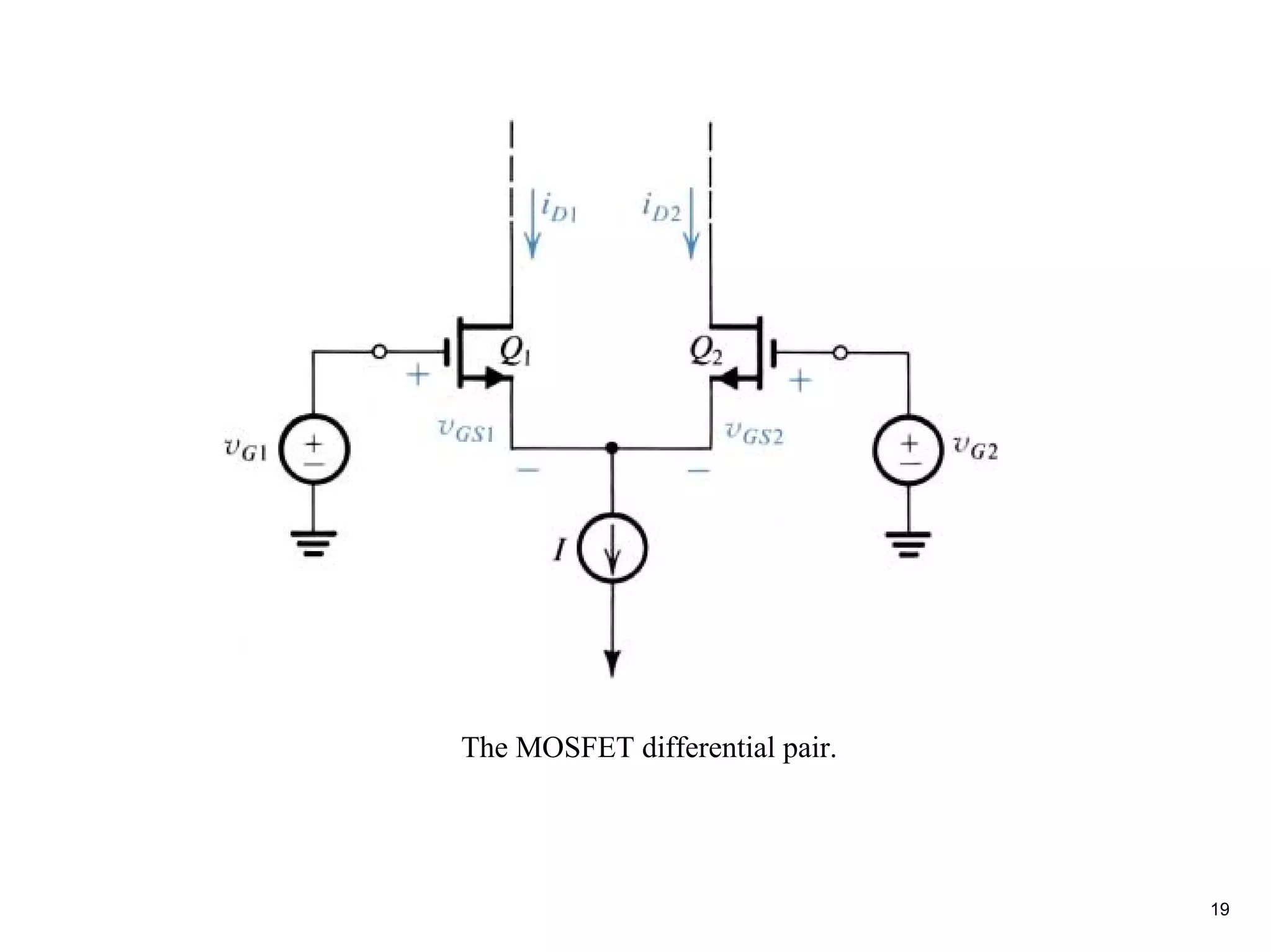
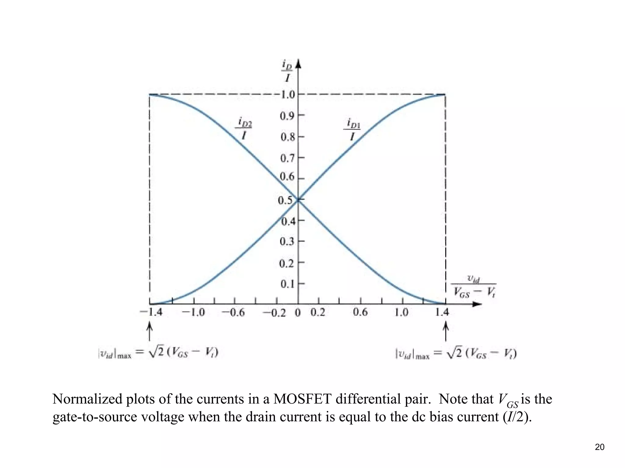
Normalized plots ofthe currents in a MOSFET differential pair. Note that VGS is the
gate-to-source voltage when the drain current is equal to the dc bias current (I/2).
20