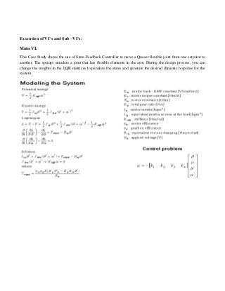
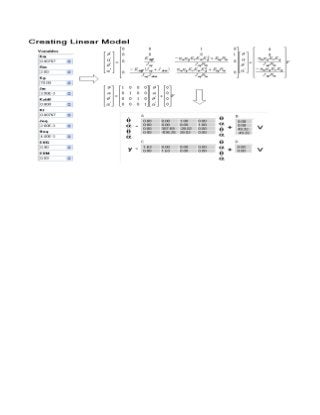
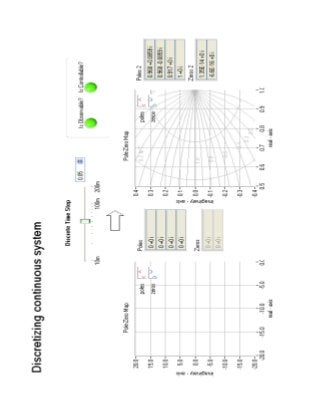
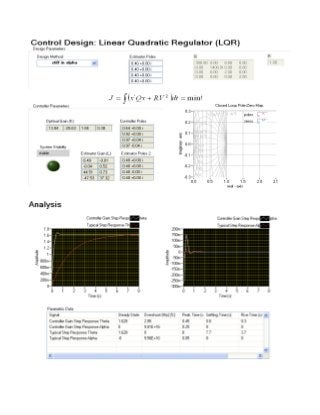
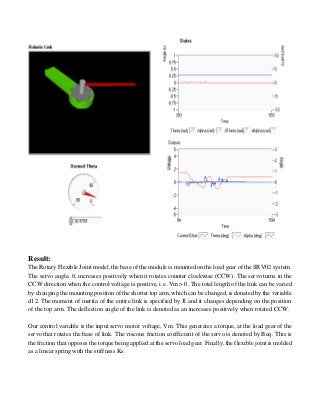
EXPERIMENT 6
AIM:
To study and design the implementation of CDEx flexible joints.
Apparatus Used:
Microsoft Windows XP, Professional Version 2002, Intel® Pentium® Dual CPU. E2180 @2.00
GHz, 2.00 GHz, 199 GB of RAM, Lab VIEW Robotics 2011 SP1
Theory:
LabVIEW (short for The Laboratory Virtual Instrumentation Engineering Workbench) is a platform and
development environment for a visual programming language from National Instruments in which you
create programs using a graphical natation (connecting functional nodes via wires through which data
flows), in this regard, it differs from traditional programming languages like C, C++, or Java in which you
program with text. However LabVIEW is much more than a programming language. It is an interactive
program development and execution system designed for people, like scientists and engineers, who need
to program as part of their jobs. The LabVIEW development environment works on computers running
Windows, Mac OS X, or Linux. LabVIEW can create programs that run on those platforms, as well as
Microsoft Pocket PC Microsoft windows CE, Palm OS, and a variety of embedded platforms, including
Field Programmable Gate Arrays (FPGAs), Digital Signal Processors (DSP), and Microprocessors.
Procedure:
Execution is determined by the structure of a graphical block diagram on which the programmer connects
different function nodes by drawing wires. These wires propagate variables and any node can execute as
soon as all its input data become available. LabVIEW ties the creation of user interface (front panels) into
the development cycle. LabVIEW programs/subroutines are called virtual instruments (VIs). Each VI has
three components; a block diagram, a front panel, and a connector panel. The last is used to represent the
VI in the block diagram of other, calling VI. Controls and indicators on the front panel allow an operator
to input data into or extract data from a running virtual instrument. However, the front panel can also serve
as a programmatic interface. Thus a VI can either be run as a program, with the front panel serving as a
user interface, or when dropped as a node onto the block diagram, the font panel defines the inputs and
outputs for the given node through the connector pane. This implies each VI can be easily tested before
being embedded as a subroutine into a larger program. The graphical approach also allows non-
programmers to build programs simply by dragging and dropping virtual representation of lab equipment
with which they are already familiar.
Execution of VI’s and Sub –VI’s:
Main VI:
This Case Study shows the use of State-Feedback Controller to move a Quaser flexible joint from one setpoint to
another. The springs simulate a joint that has flexible elements in the arm. During the design process, you can
change the weights in the LQR matrices to penalize the states and generate the desired dynamic response for the
system.
Result:
The Rotary Flexible Joint model, the base of the module is mounted on the load gear of the SRV02 system.
The servo angle, , increases positively when it rotates counter clockwise (CCW). The servo turns in the
CCW direction when the control voltage is positive, i.e. Vm > 0. The total length of the link can be varied
by changing the mounting position of the shorter top arm, which can be changed, is donated by the variable
d12. The moment of inertia of the entire link is specified by Jl and it changes depending on the position
of the top arm. The deflection angle of the link is denoted as an increases positively when rotated CCW.
Our control variable is the input servo motor voltage, Vm. This generates a torque, at the load gear of the
servo that rotates the base of link. The viscous friction coefficient of the servo is denoted by Beq. This is
the friction that opposes the torque being applied at the servo load gear. Finally, the flexible joint is molded
as a linear spring with the stiffness Ks.
Precautions:
 To avoid hanging the user interface with front panel locking, configure all events you want a VI to
handle in a single Event structure or always make sure there is only one Event structure in a loop.
 Additionally, make sure there is always an Event structure available to handle events as they occur.

Design the implementation of CDEx flexible joints

  • 1.
    EXPERIMENT 6 AIM: To studyand design the implementation of CDEx flexible joints. Apparatus Used: Microsoft Windows XP, Professional Version 2002, Intel® Pentium® Dual CPU. E2180 @2.00 GHz, 2.00 GHz, 199 GB of RAM, Lab VIEW Robotics 2011 SP1 Theory: LabVIEW (short for The Laboratory Virtual Instrumentation Engineering Workbench) is a platform and development environment for a visual programming language from National Instruments in which you create programs using a graphical natation (connecting functional nodes via wires through which data flows), in this regard, it differs from traditional programming languages like C, C++, or Java in which you program with text. However LabVIEW is much more than a programming language. It is an interactive program development and execution system designed for people, like scientists and engineers, who need to program as part of their jobs. The LabVIEW development environment works on computers running Windows, Mac OS X, or Linux. LabVIEW can create programs that run on those platforms, as well as Microsoft Pocket PC Microsoft windows CE, Palm OS, and a variety of embedded platforms, including Field Programmable Gate Arrays (FPGAs), Digital Signal Processors (DSP), and Microprocessors. Procedure: Execution is determined by the structure of a graphical block diagram on which the programmer connects different function nodes by drawing wires. These wires propagate variables and any node can execute as soon as all its input data become available. LabVIEW ties the creation of user interface (front panels) into the development cycle. LabVIEW programs/subroutines are called virtual instruments (VIs). Each VI has three components; a block diagram, a front panel, and a connector panel. The last is used to represent the VI in the block diagram of other, calling VI. Controls and indicators on the front panel allow an operator to input data into or extract data from a running virtual instrument. However, the front panel can also serve as a programmatic interface. Thus a VI can either be run as a program, with the front panel serving as a user interface, or when dropped as a node onto the block diagram, the font panel defines the inputs and outputs for the given node through the connector pane. This implies each VI can be easily tested before being embedded as a subroutine into a larger program. The graphical approach also allows non- programmers to build programs simply by dragging and dropping virtual representation of lab equipment with which they are already familiar.
  • 2.
    Execution of VI’sand Sub –VI’s: Main VI: This Case Study shows the use of State-Feedback Controller to move a Quaser flexible joint from one setpoint to another. The springs simulate a joint that has flexible elements in the arm. During the design process, you can change the weights in the LQR matrices to penalize the states and generate the desired dynamic response for the system.
  • 6.
    Result: The Rotary FlexibleJoint model, the base of the module is mounted on the load gear of the SRV02 system. The servo angle, , increases positively when it rotates counter clockwise (CCW). The servo turns in the CCW direction when the control voltage is positive, i.e. Vm > 0. The total length of the link can be varied by changing the mounting position of the shorter top arm, which can be changed, is donated by the variable d12. The moment of inertia of the entire link is specified by Jl and it changes depending on the position of the top arm. The deflection angle of the link is denoted as an increases positively when rotated CCW. Our control variable is the input servo motor voltage, Vm. This generates a torque, at the load gear of the servo that rotates the base of link. The viscous friction coefficient of the servo is denoted by Beq. This is the friction that opposes the torque being applied at the servo load gear. Finally, the flexible joint is molded as a linear spring with the stiffness Ks.
  • 7.
    Precautions:  To avoidhanging the user interface with front panel locking, configure all events you want a VI to handle in a single Event structure or always make sure there is only one Event structure in a loop.  Additionally, make sure there is always an Event structure available to handle events as they occur.