Downloaded 281 times
![ Weaving width is calculated as,
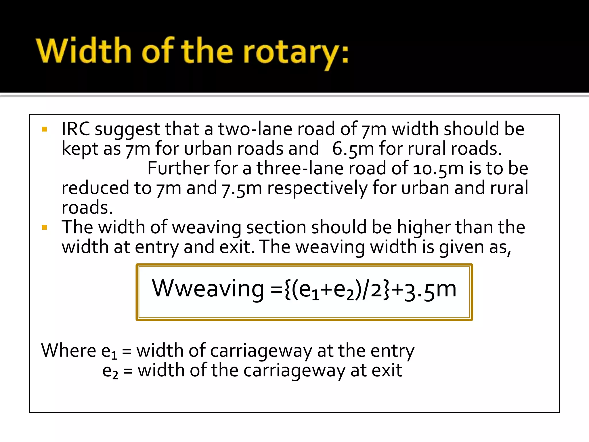
w = [(e₁+e₂)/2] + 3:5 = 13.5 m
Weaving length is calculated as
l = 4*w = 54 m
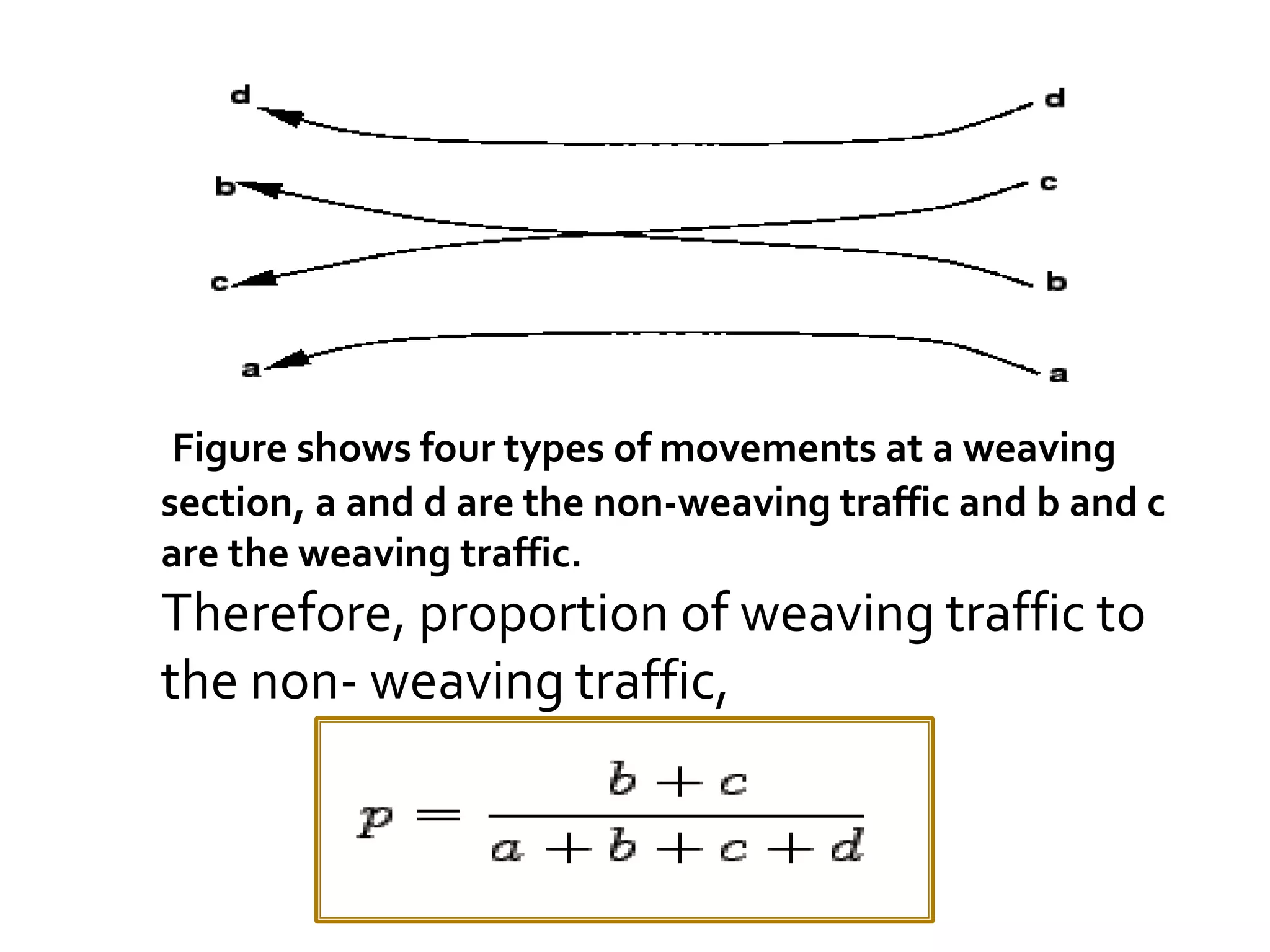
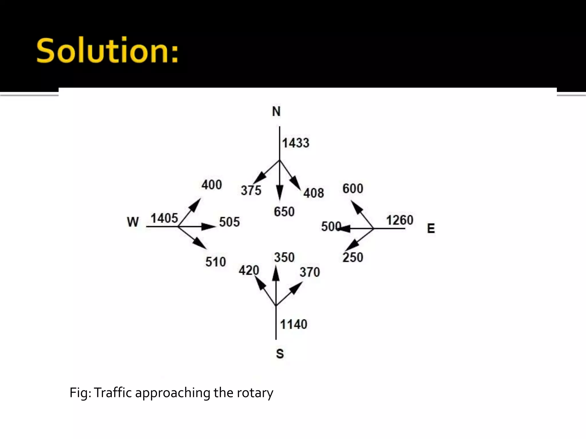
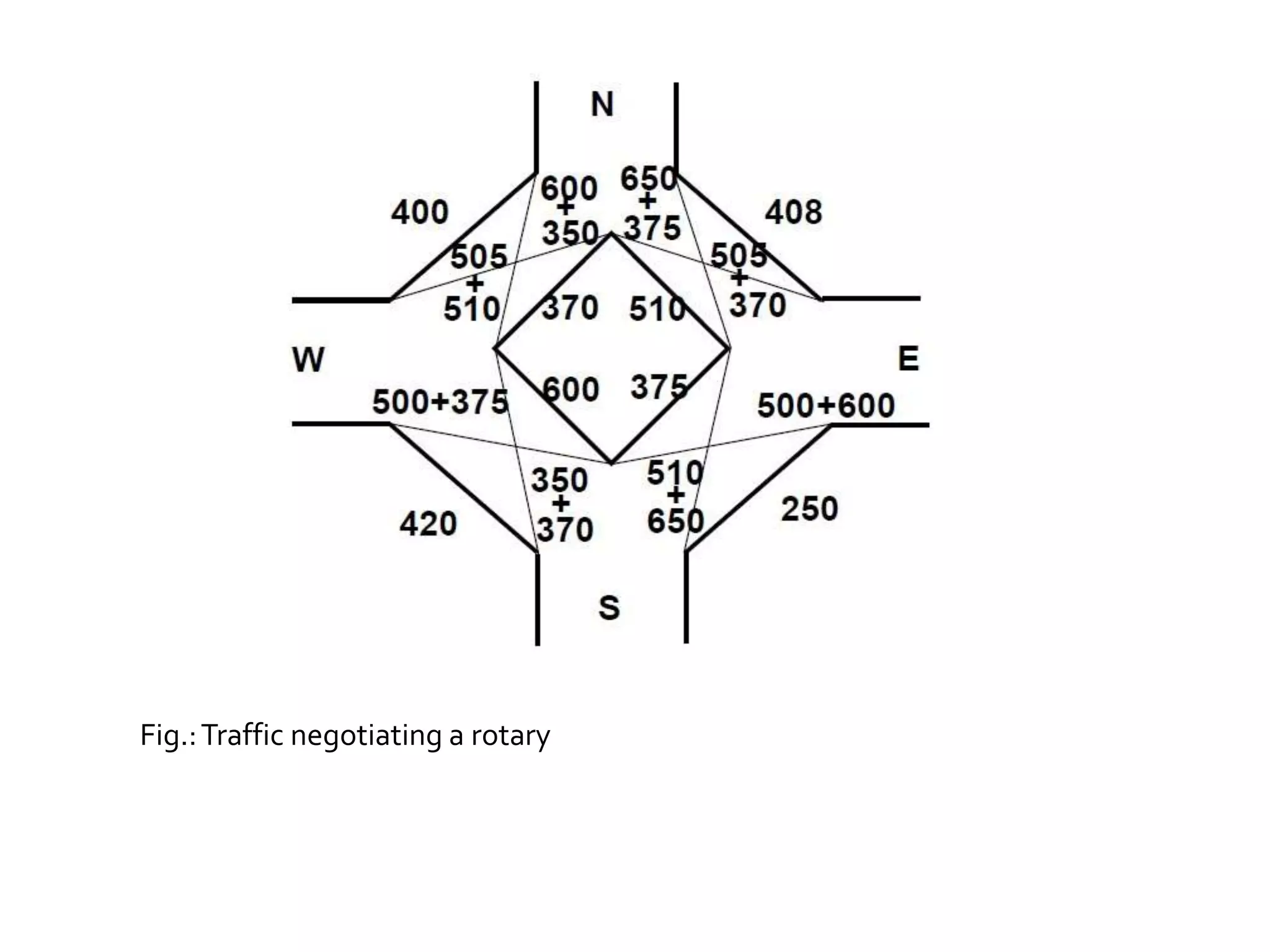
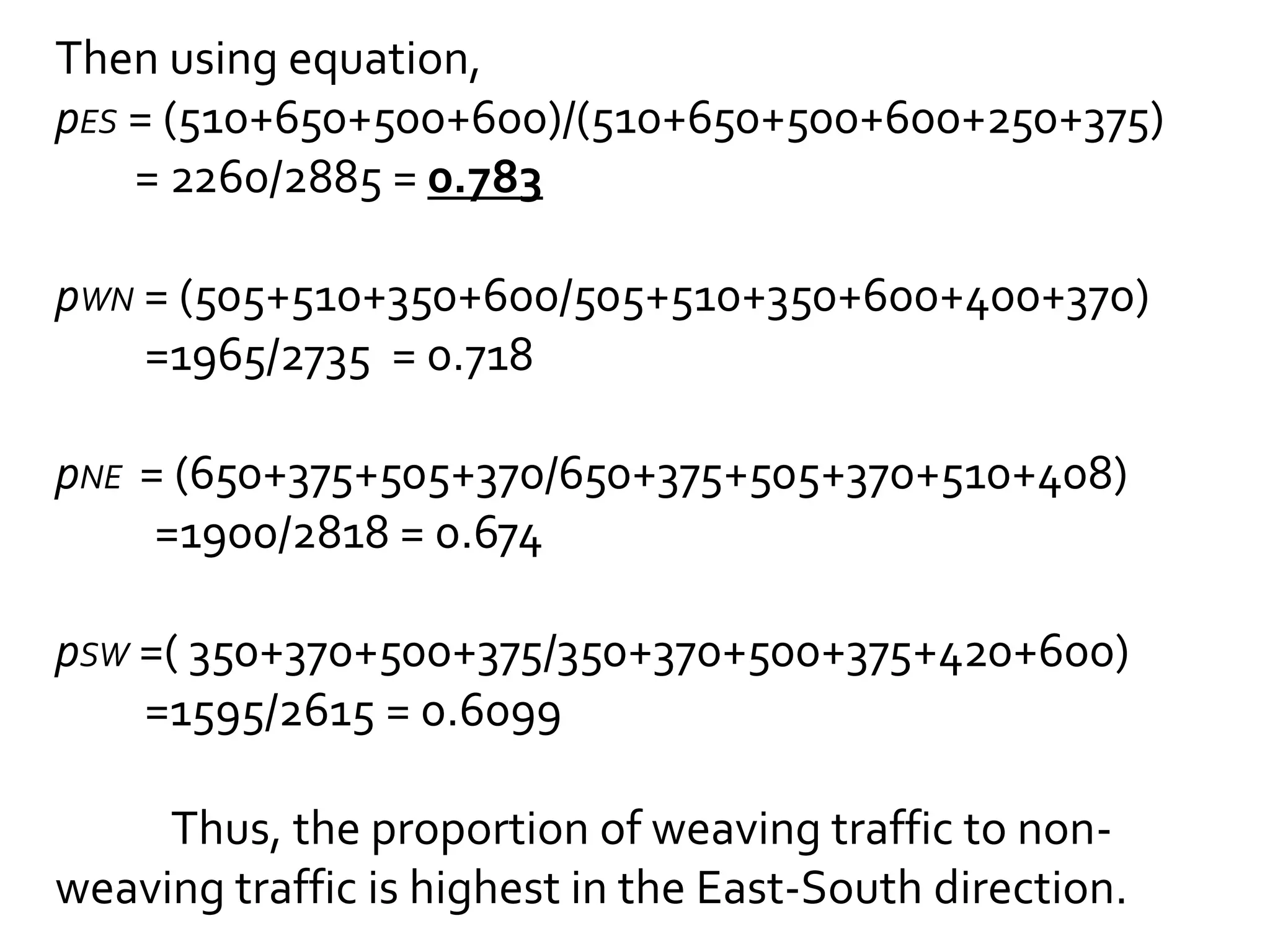
The proportion of weaving traffic to the non-weaving
traffic in all the four approaches is found out first.
Let the proportion of weaving traffic to the non-weaving
traffic in West-North direction be denoted as
pWN, in North-East direction as pNE, in the East-South
direction as pES, and finally in the South-West
direction as pSW.](https://image.slidesharecdn.com/capacityatintersection-141210093722-conversion-gate02/75/Capacity-at-intersection-24-2048.jpg)
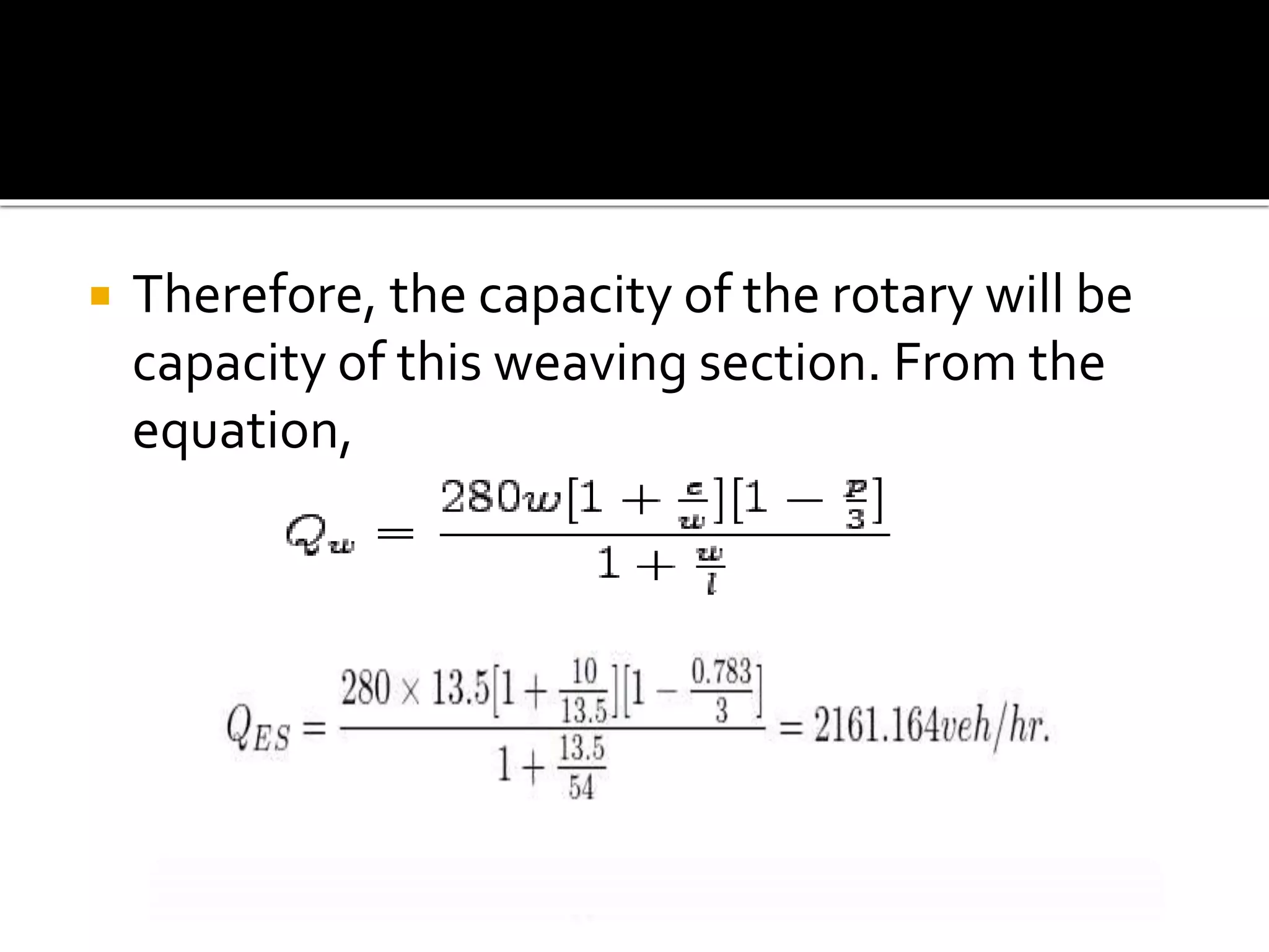


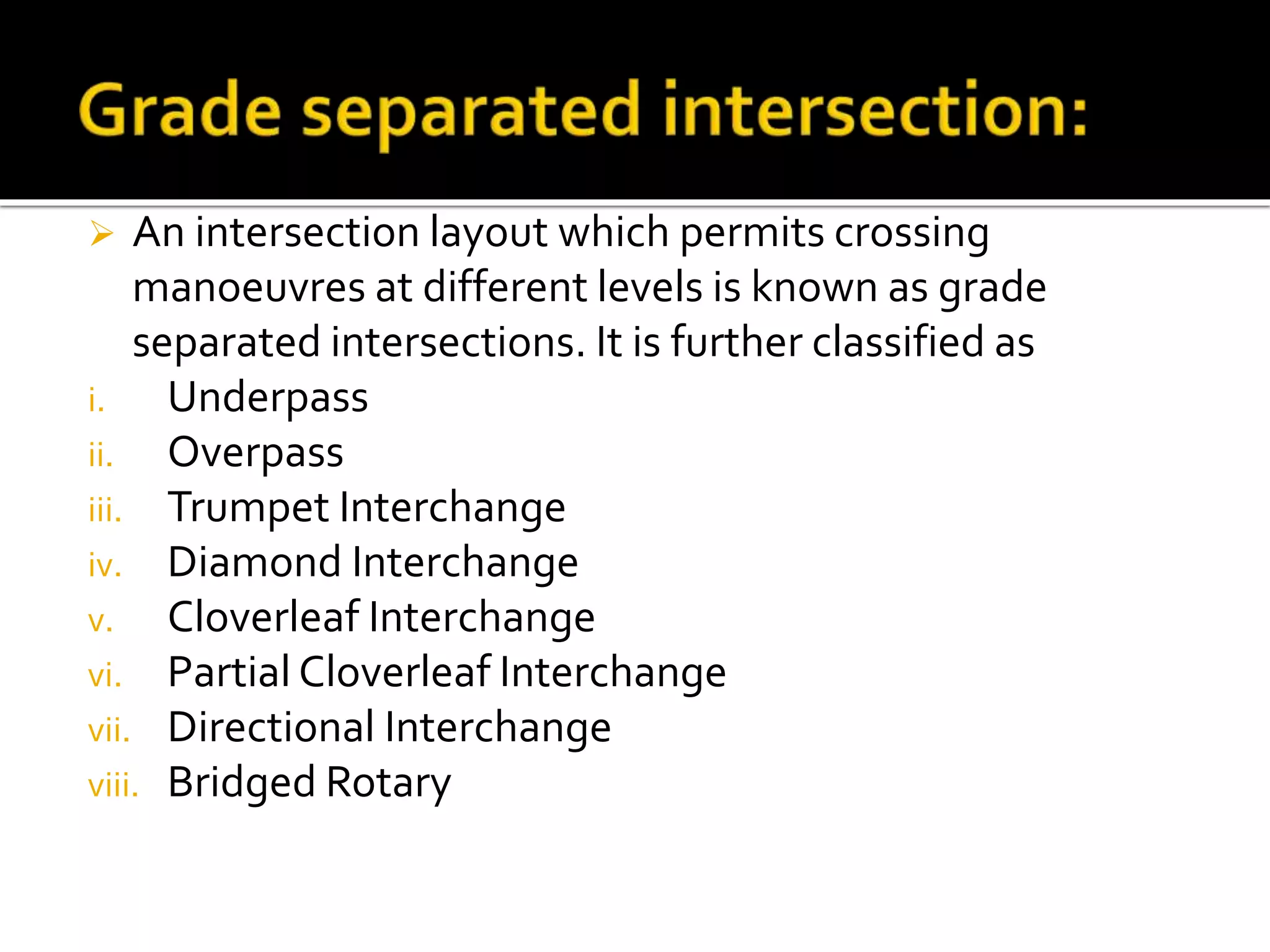
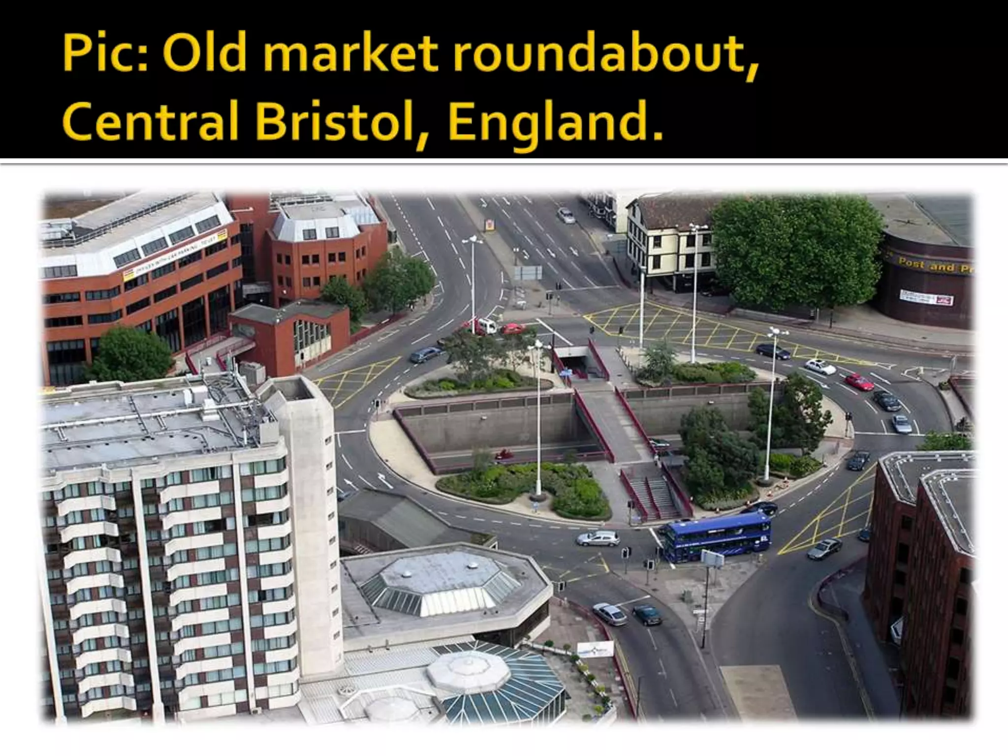
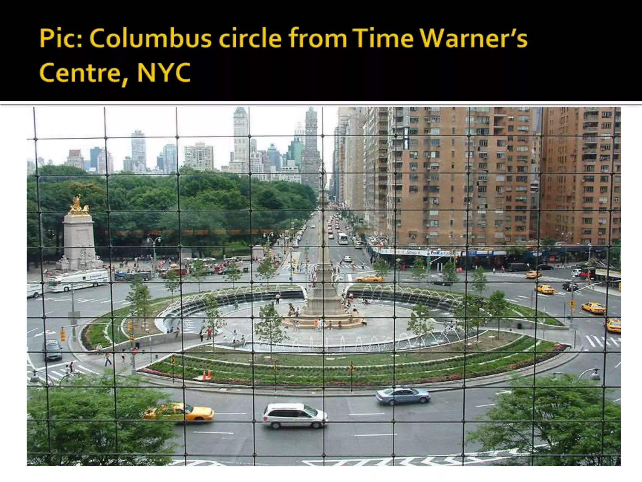
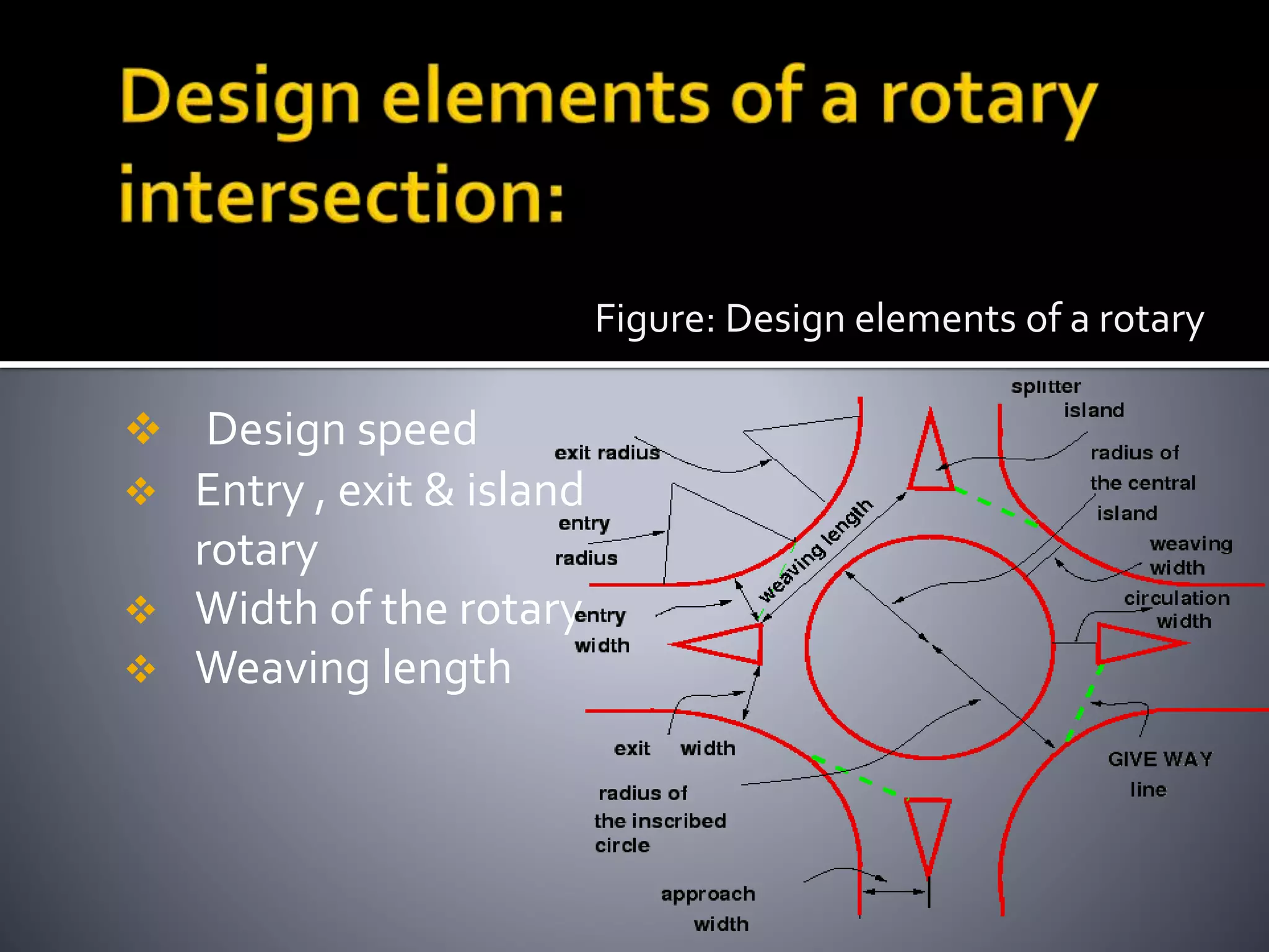
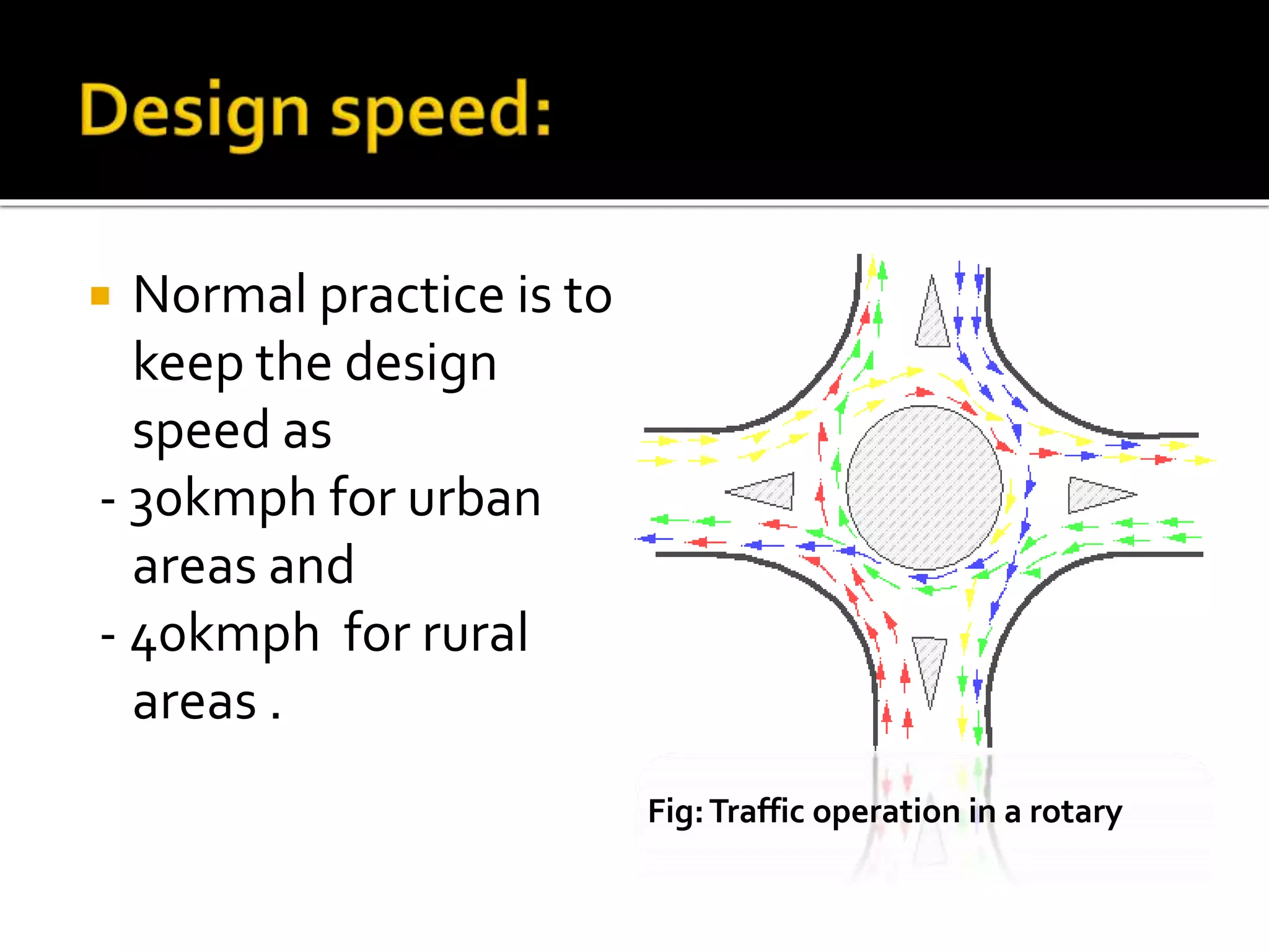
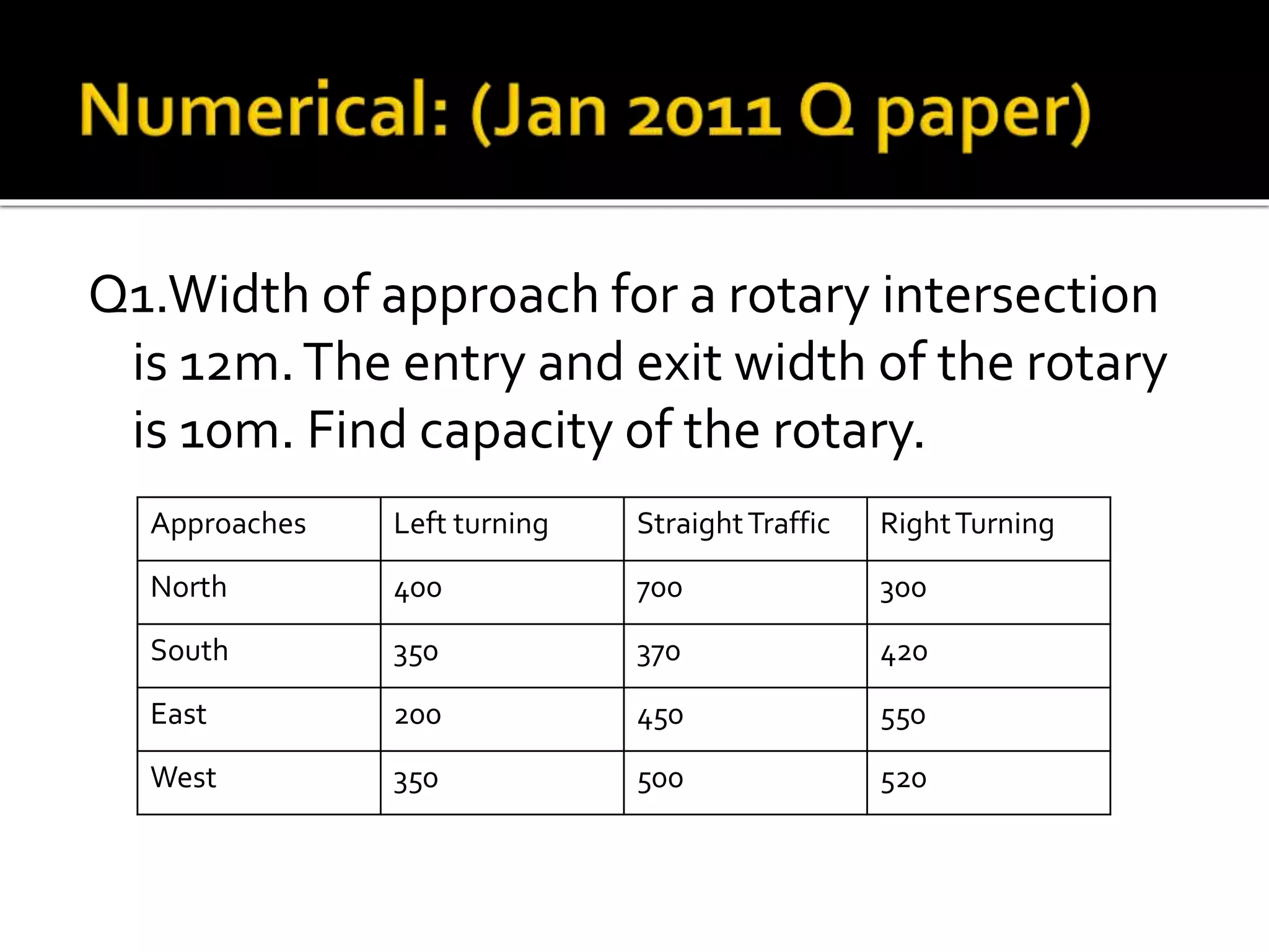
This document discusses different types of intersections, focusing on rotary intersections. It defines a rotary intersection as a special form of at-grade intersection where traffic circulates around a central island in a clockwise direction. The key design elements of a rotary are then outlined, including entry and exit radii, island radius, width, and weaving length. A formula from the Transportation Road Research Lab is presented for calculating a rotary's capacity based on the weaving section with the highest proportion of weaving to non-weaving traffic. An example problem demonstrates how to use the formula to determine a rotary's capacity.


![Rotary_Roundabout_Sams_03.12.14 [Compatibility Mode].pdf](https://cdn.slidesharecdn.com/ss_thumbnails/rotaryroundaboutsams03-250423055821-6dd85e6b-thumbnail.jpg?width=640&height=640&fit=bounds)


