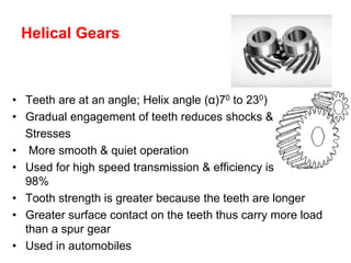
1) Helical gears operate more smoothly than spur gears due to their gradual engagement of teeth which reduces shocks and stresses. They can carry more load and are used for high speed transmission.
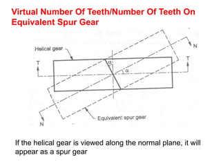
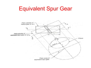
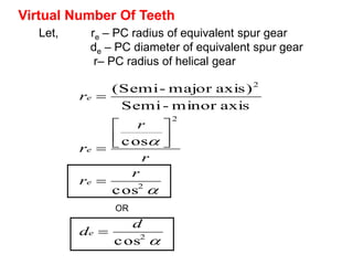
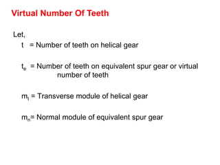
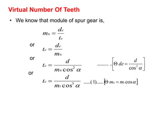
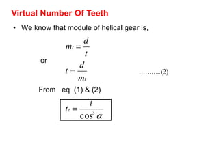
2) A helical gear can be considered equivalent to a spur gear on a normal plane, called the virtual gear or equivalent spur gear. The number of teeth on the virtual gear is called the virtual number of teeth.
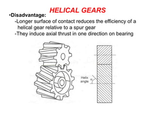
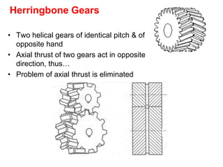
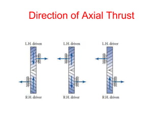
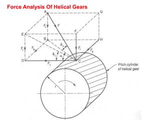
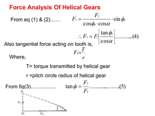
3) Helical gears experience three force components - tangential, radial, and axial. The axial force causes thrust on the bearings in one direction, which can be eliminated by using two helical gears of opposite hand.