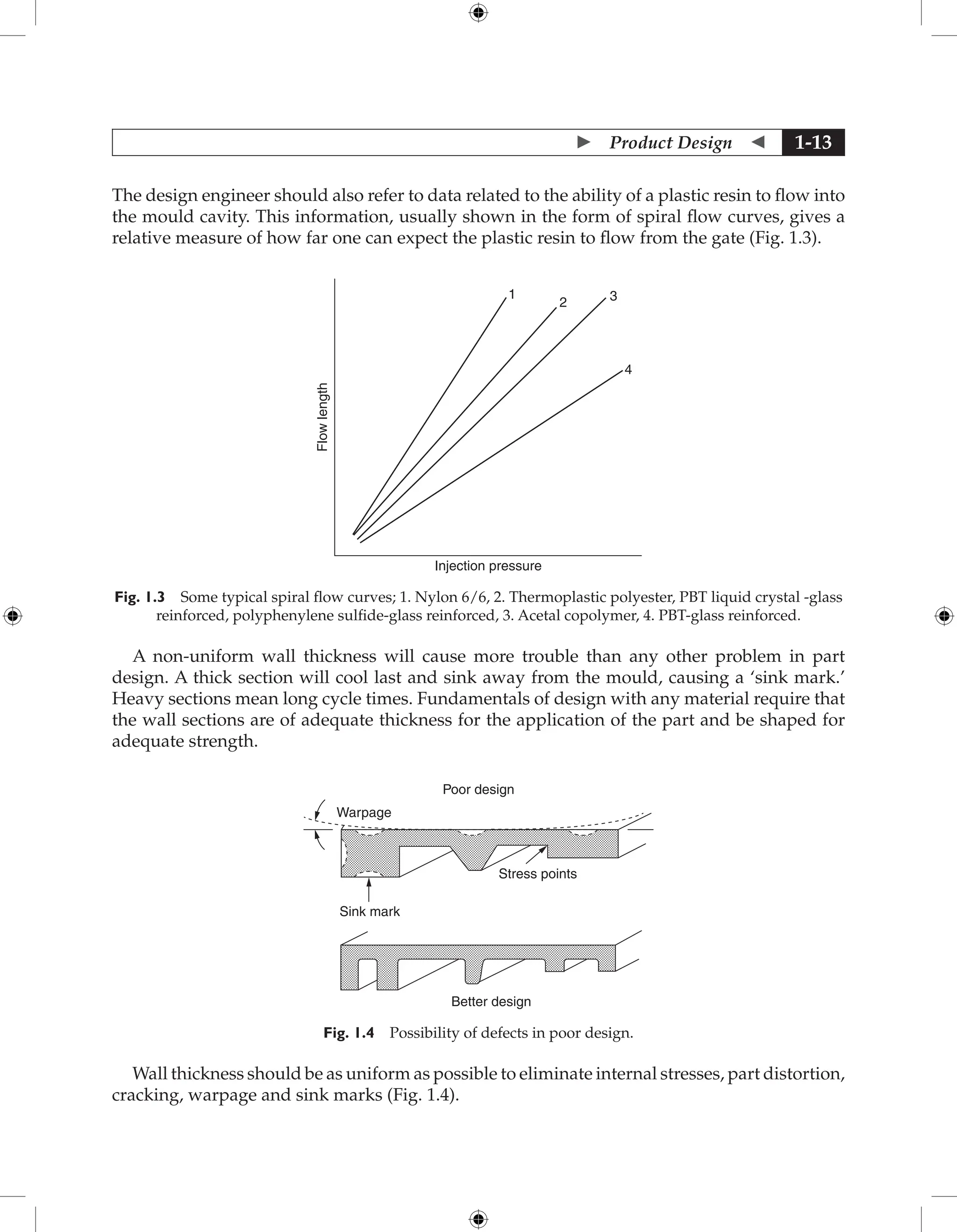
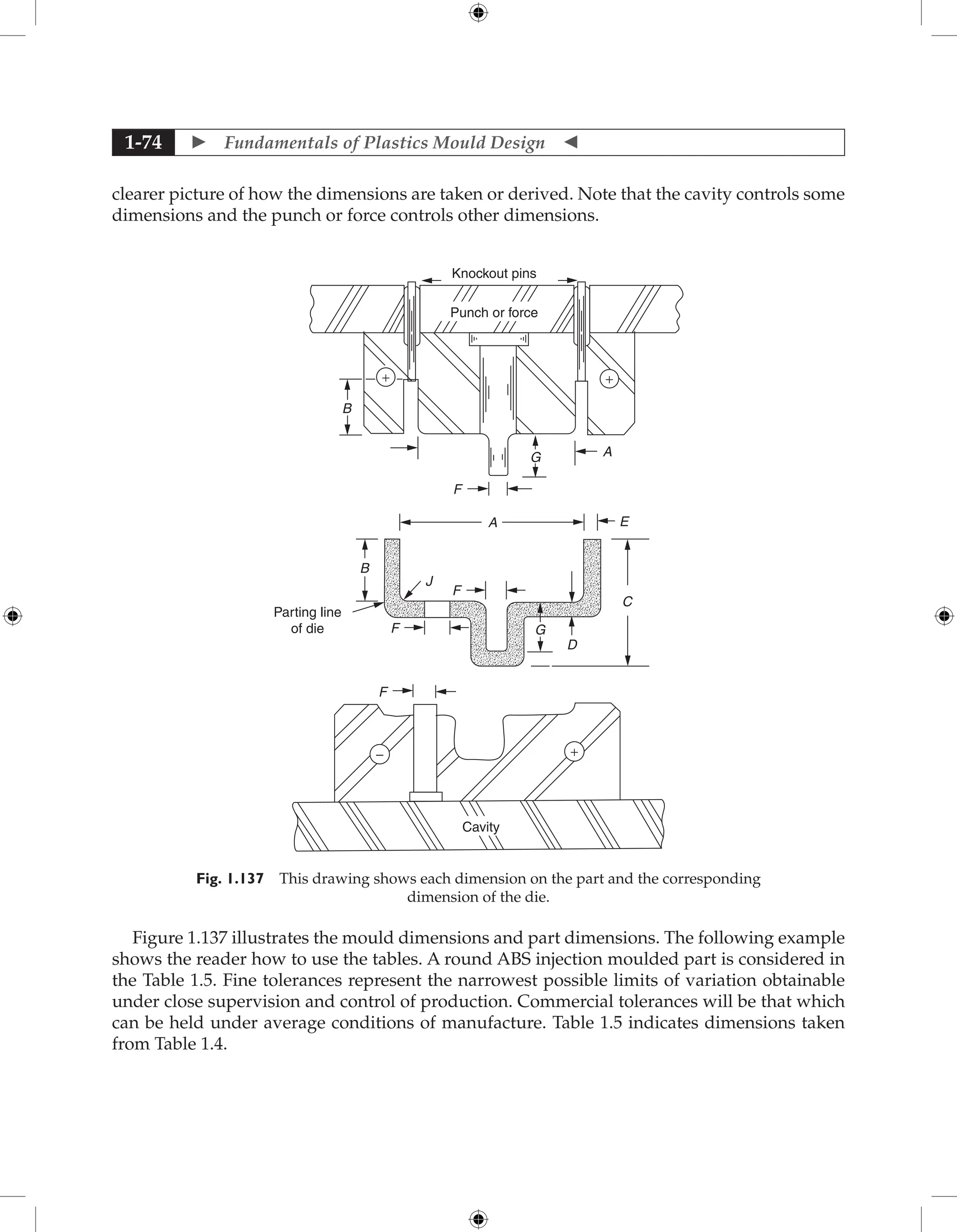
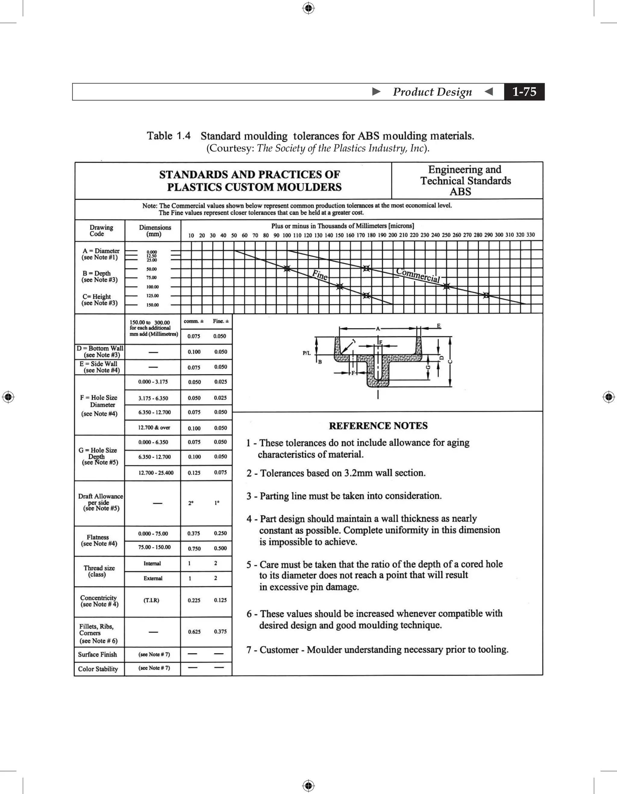
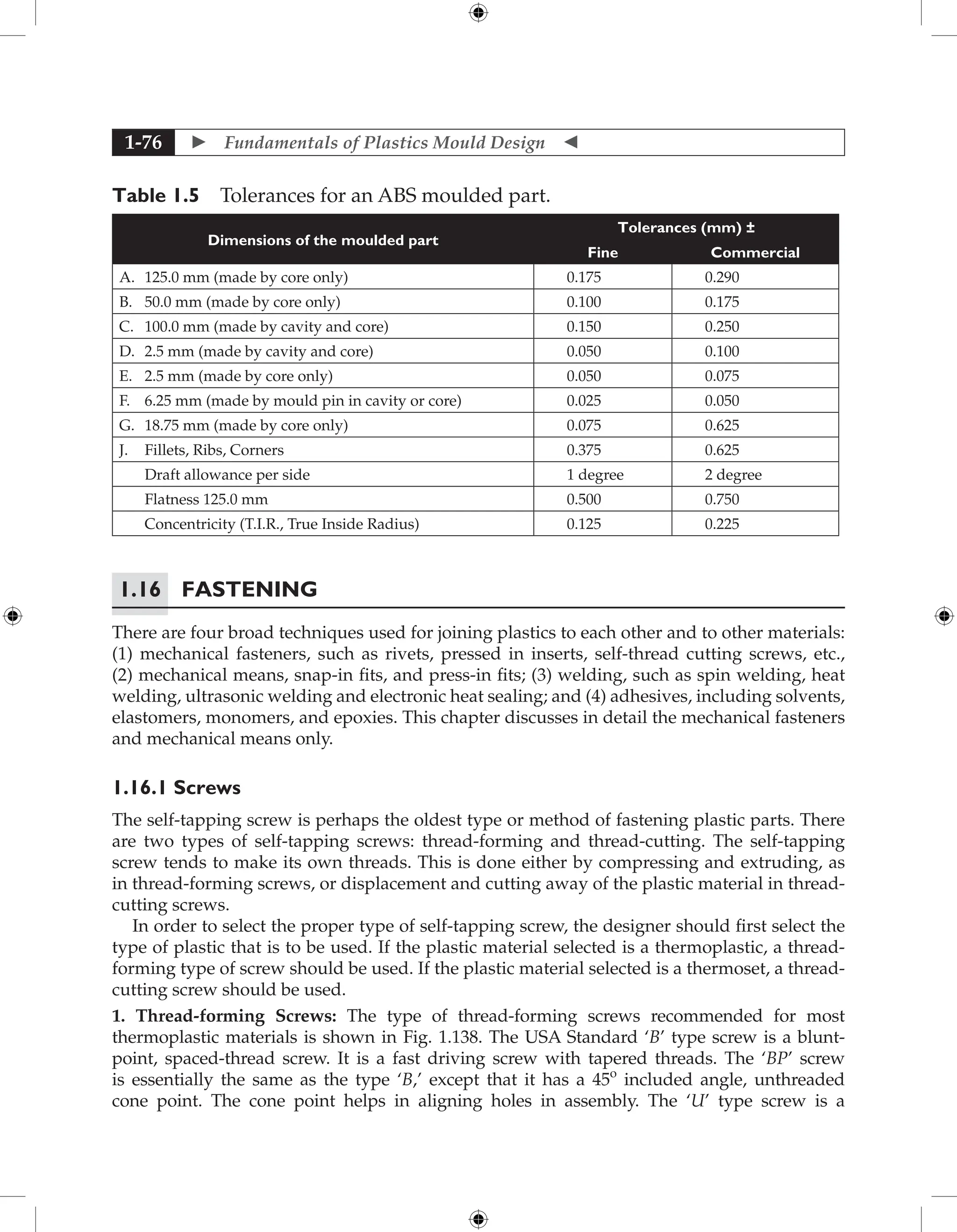
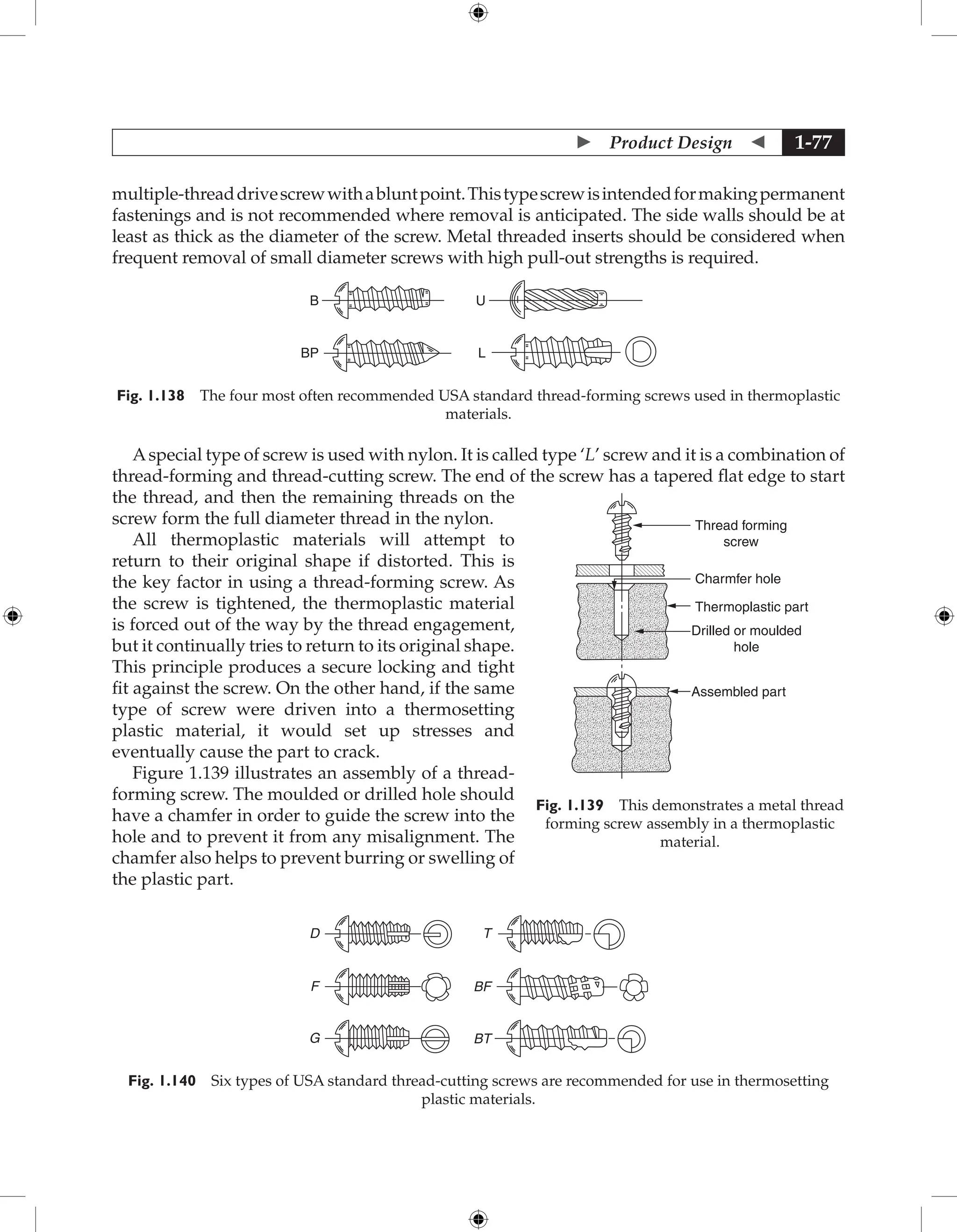
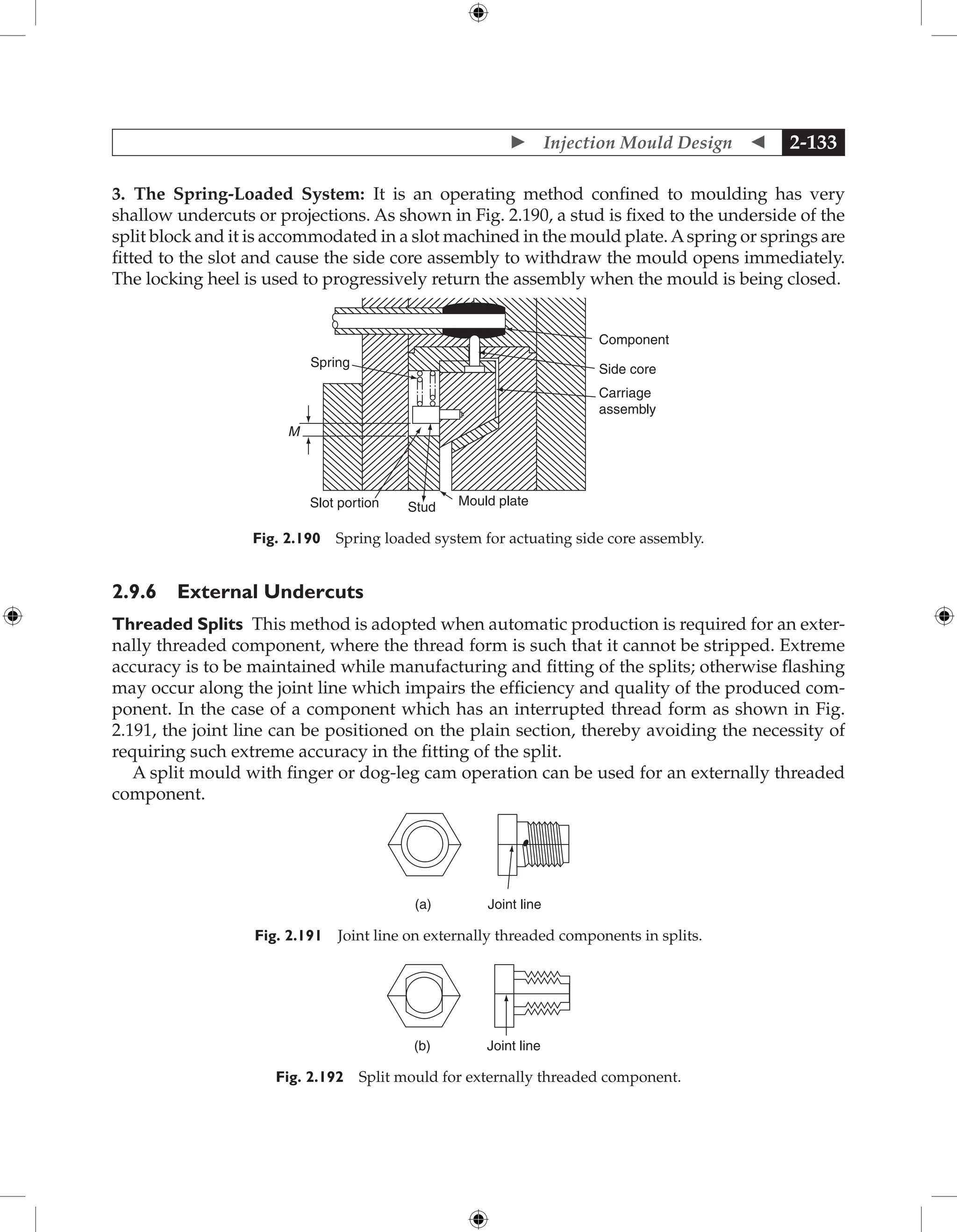
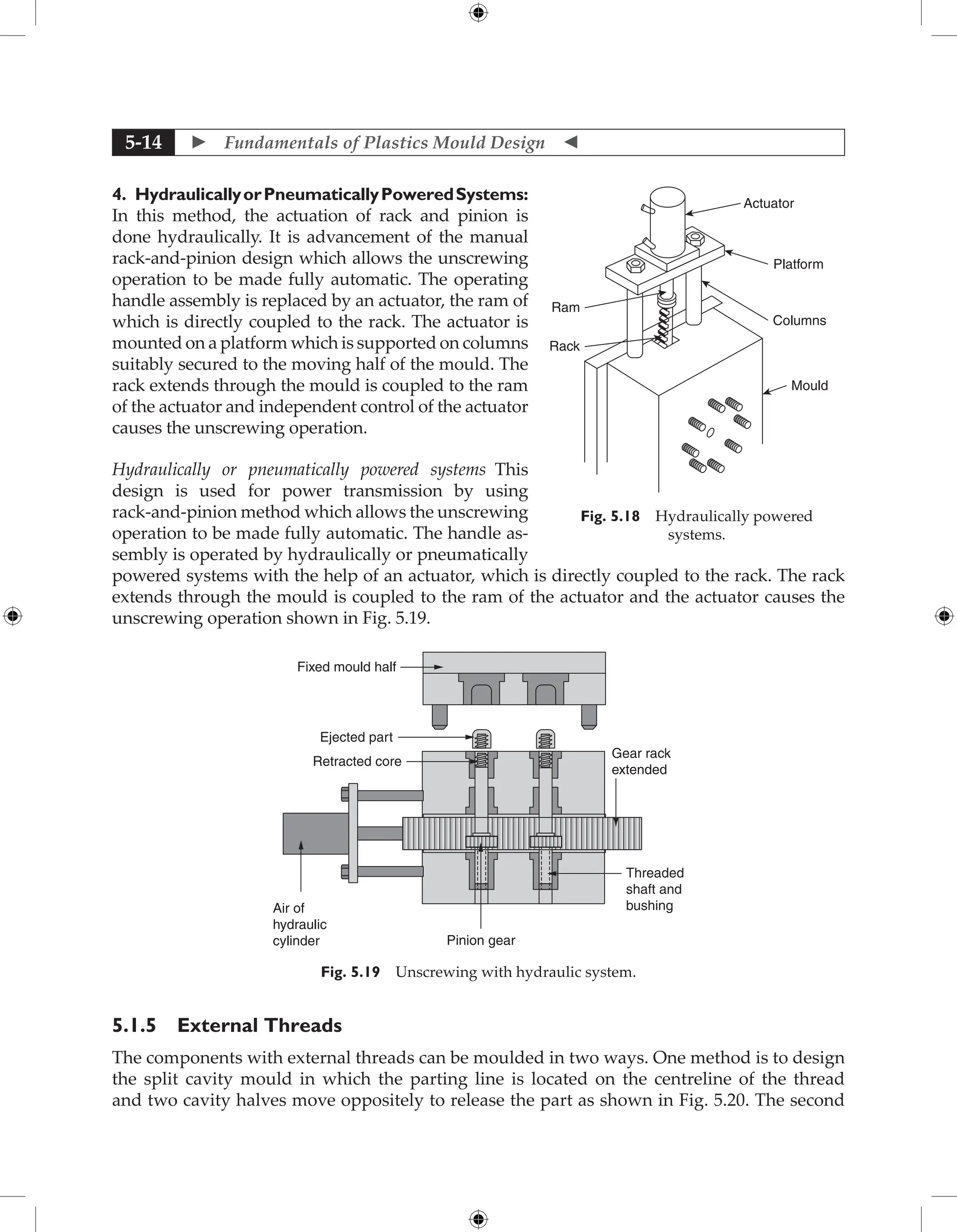
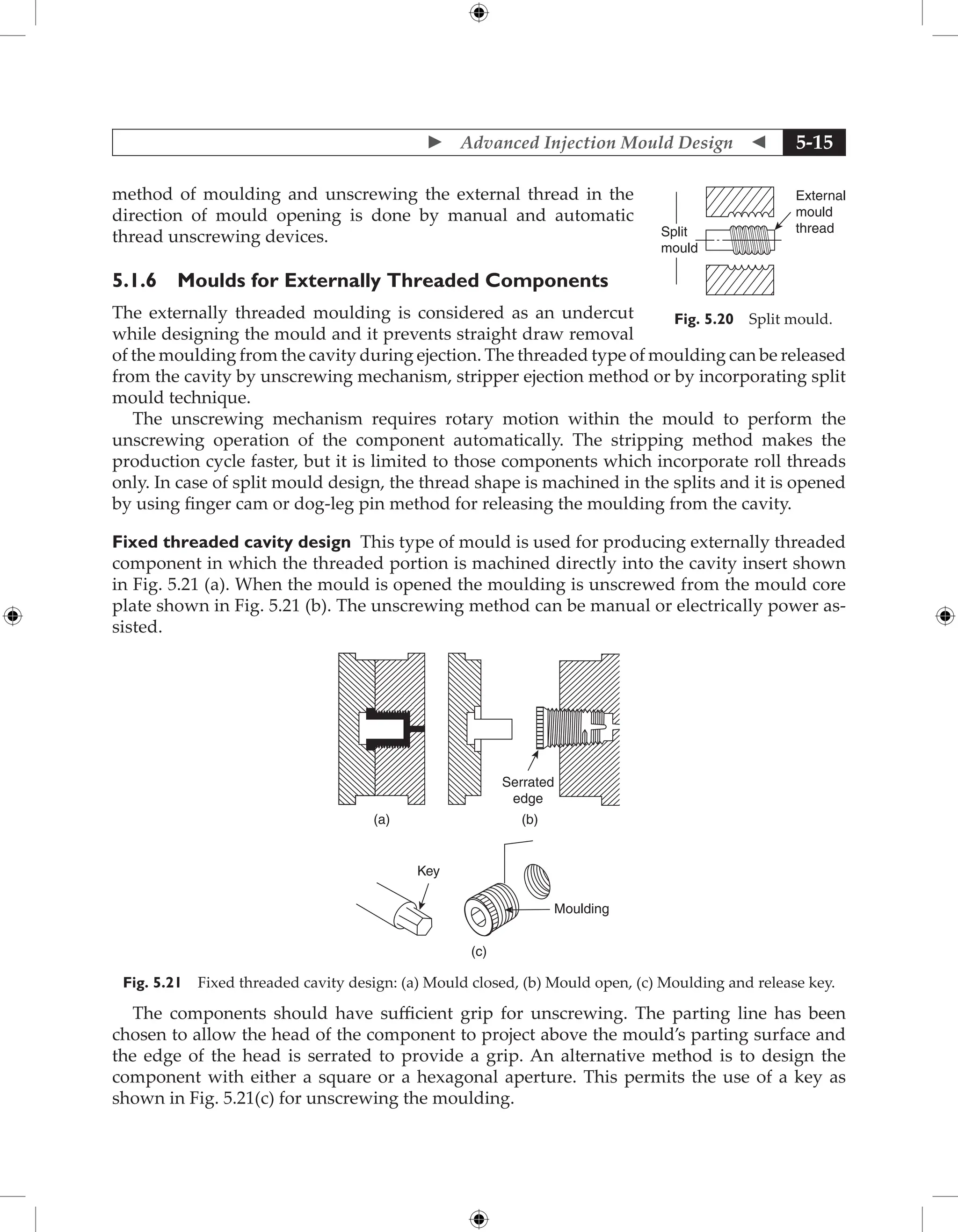
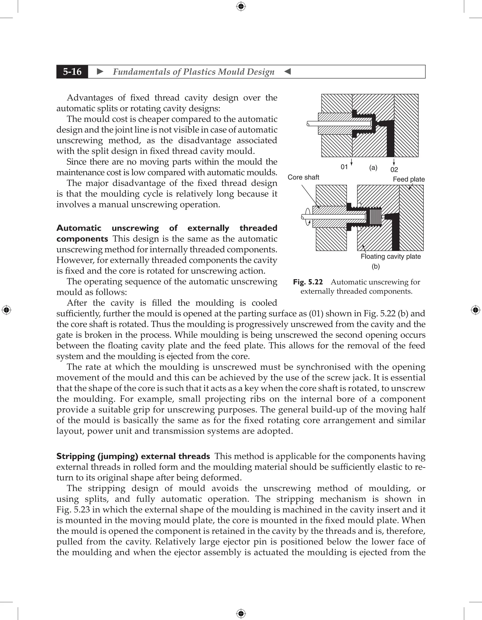
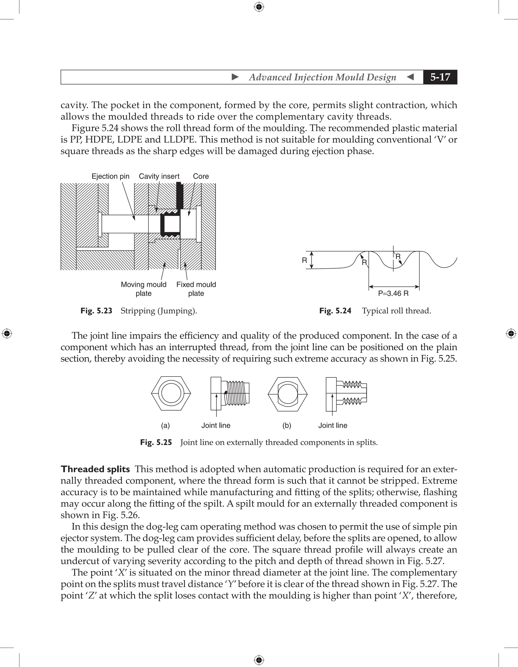
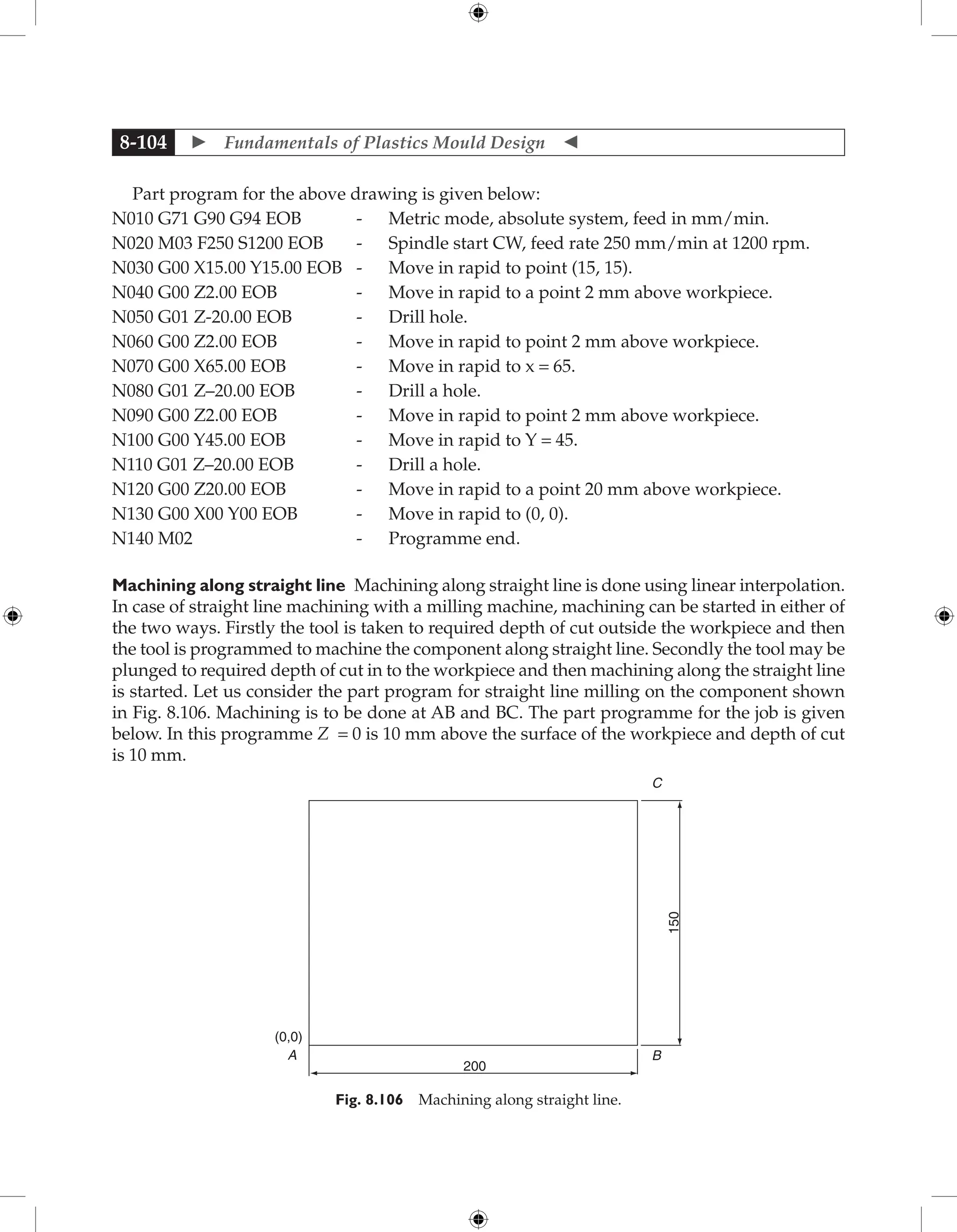
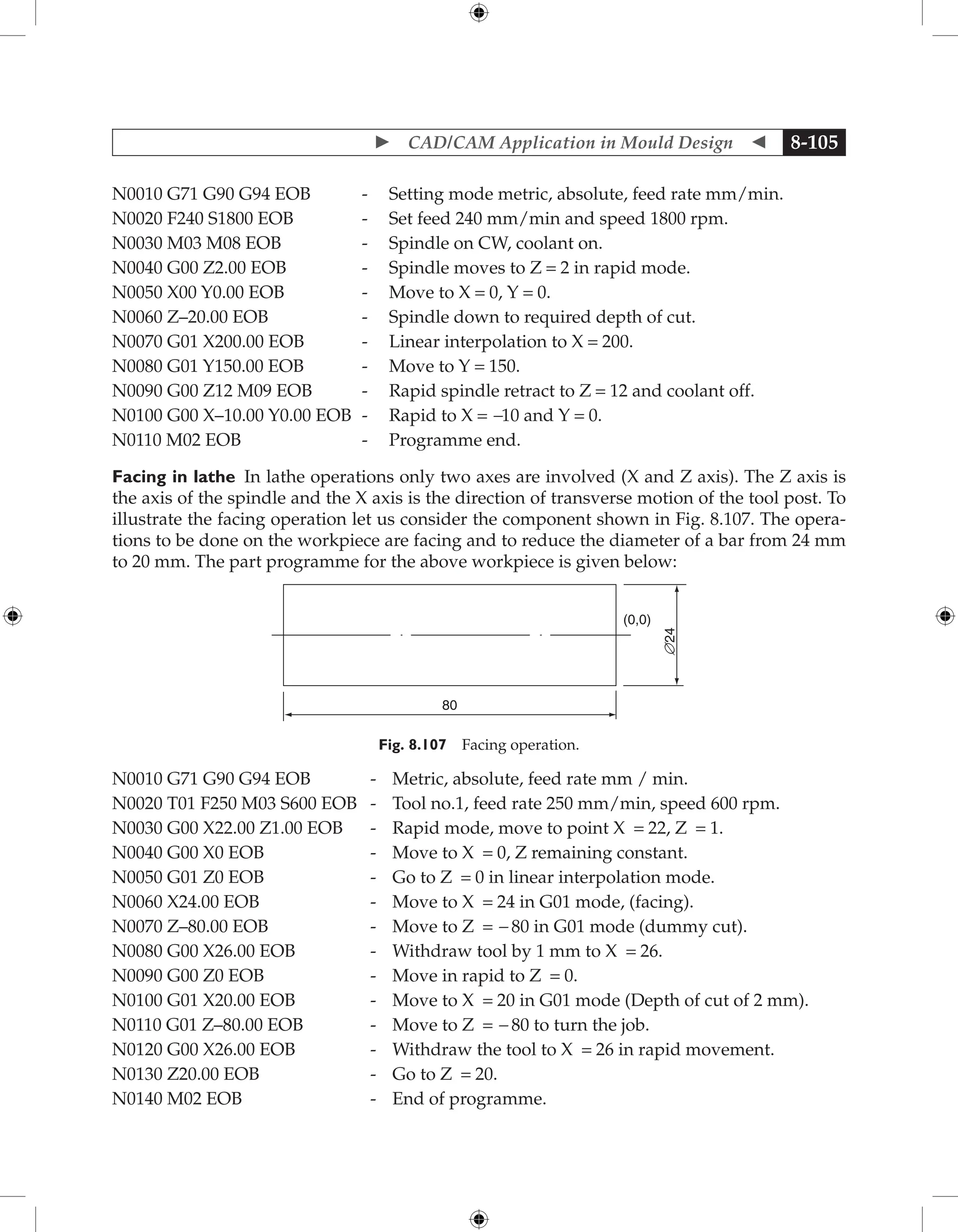
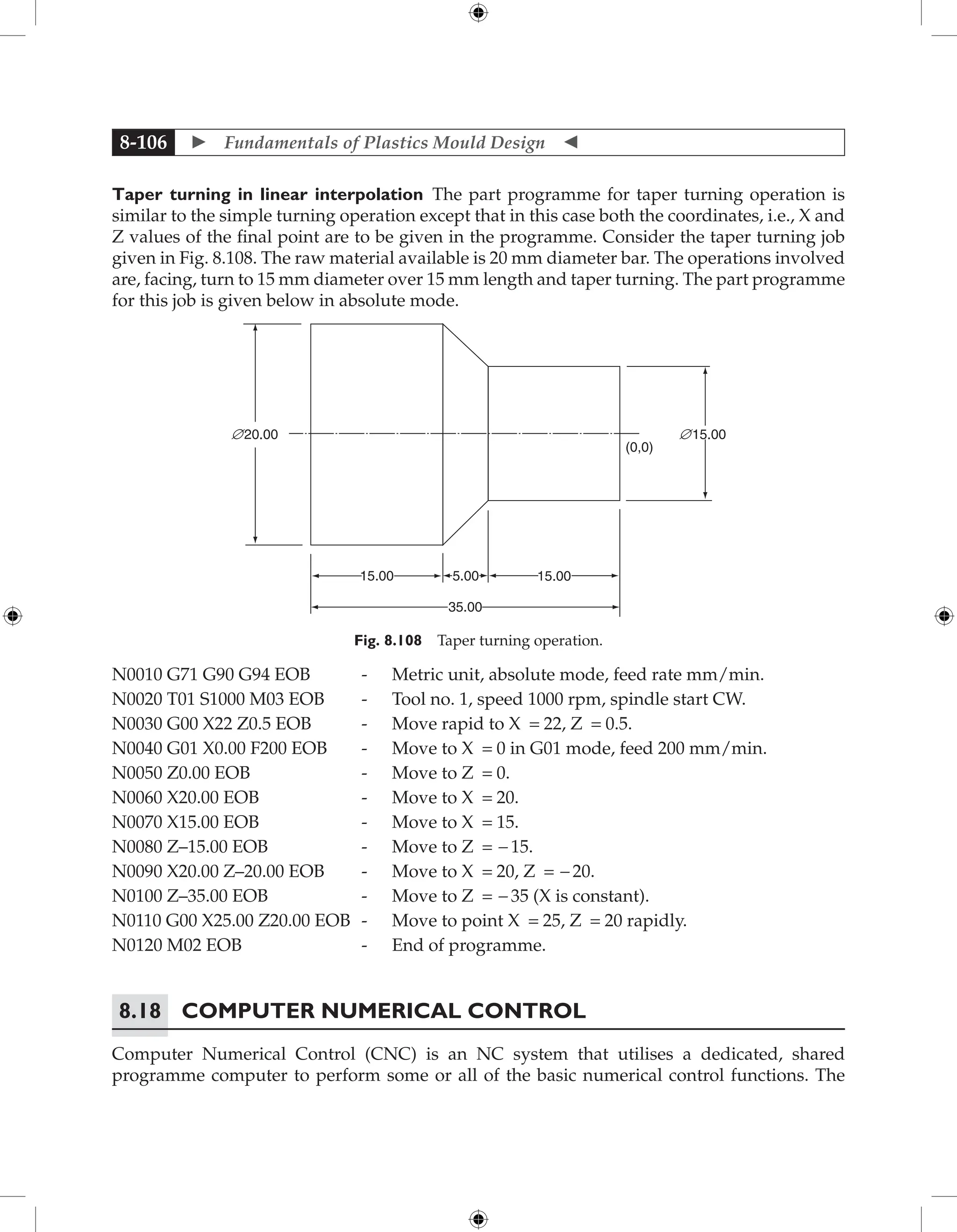
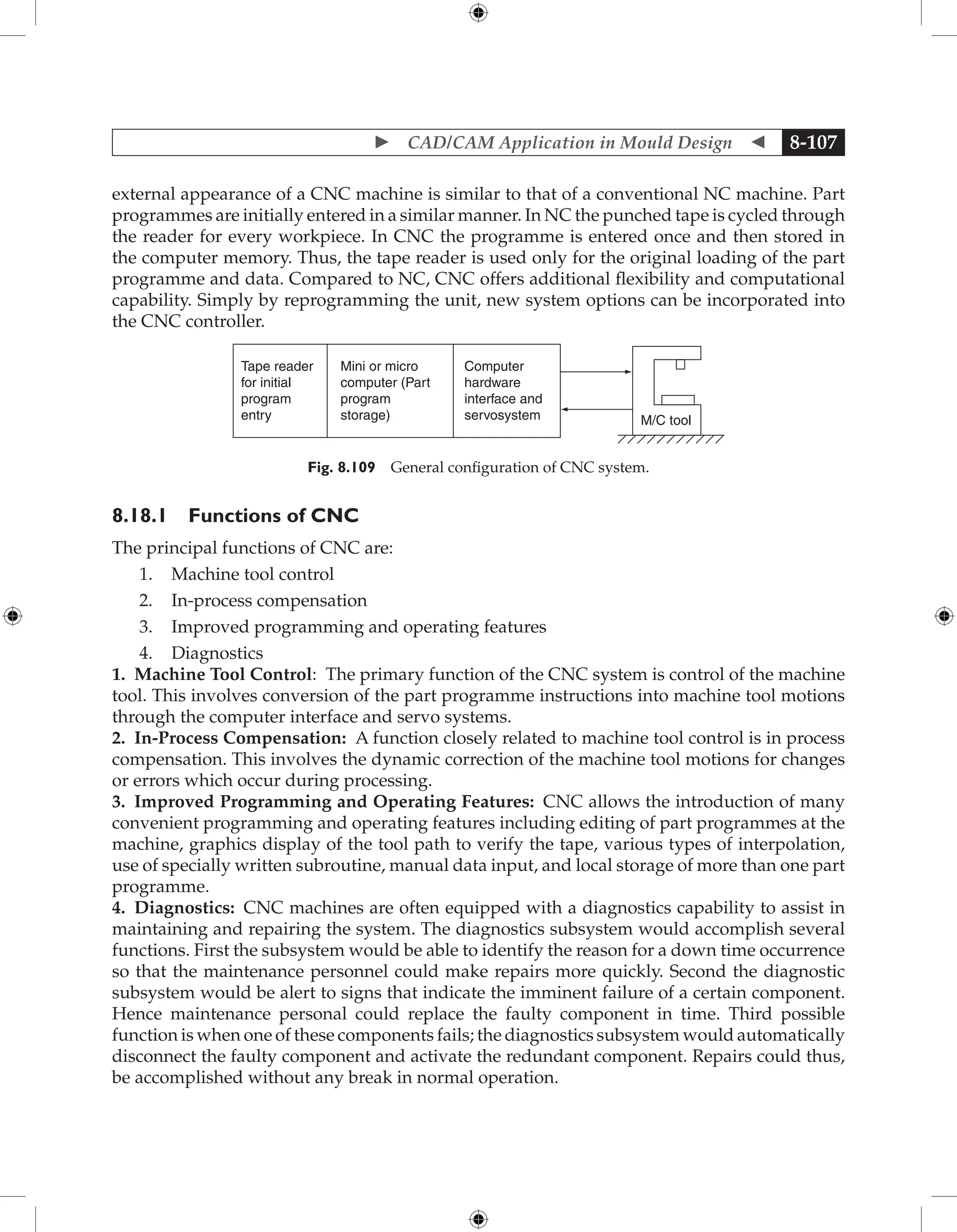
This document provides an overview and summary of the book "Fundamentals of Plastics Mould Design". The book covers fundamentals of product design, injection mould design, compression mould design, transfer mould design, blow mould design, extrusion dies design, and applications of CAD/CAM in mould design. It is intended to meet the requirements of engineering courses in plastics/polymer technology. The book includes concepts of mould design, plastic materials and processing, as well as recent technologies like CAD/CAM applications. It contains 550 questions and examples to illustrate design calculations.


![ Product Design 1-101
CYCLES TO FAILURE
12 PITCH
0
105
106
107
108
50
100
150
200
250
300
12 PITCH
4650 PLV
2750 PLV
2750 PLV
32 and 24 PITCH
20° pressure angle
73 F ambient temp.
celcon M90
APPLIED
UNIT
LOAD
(Lu)
LBS/IN
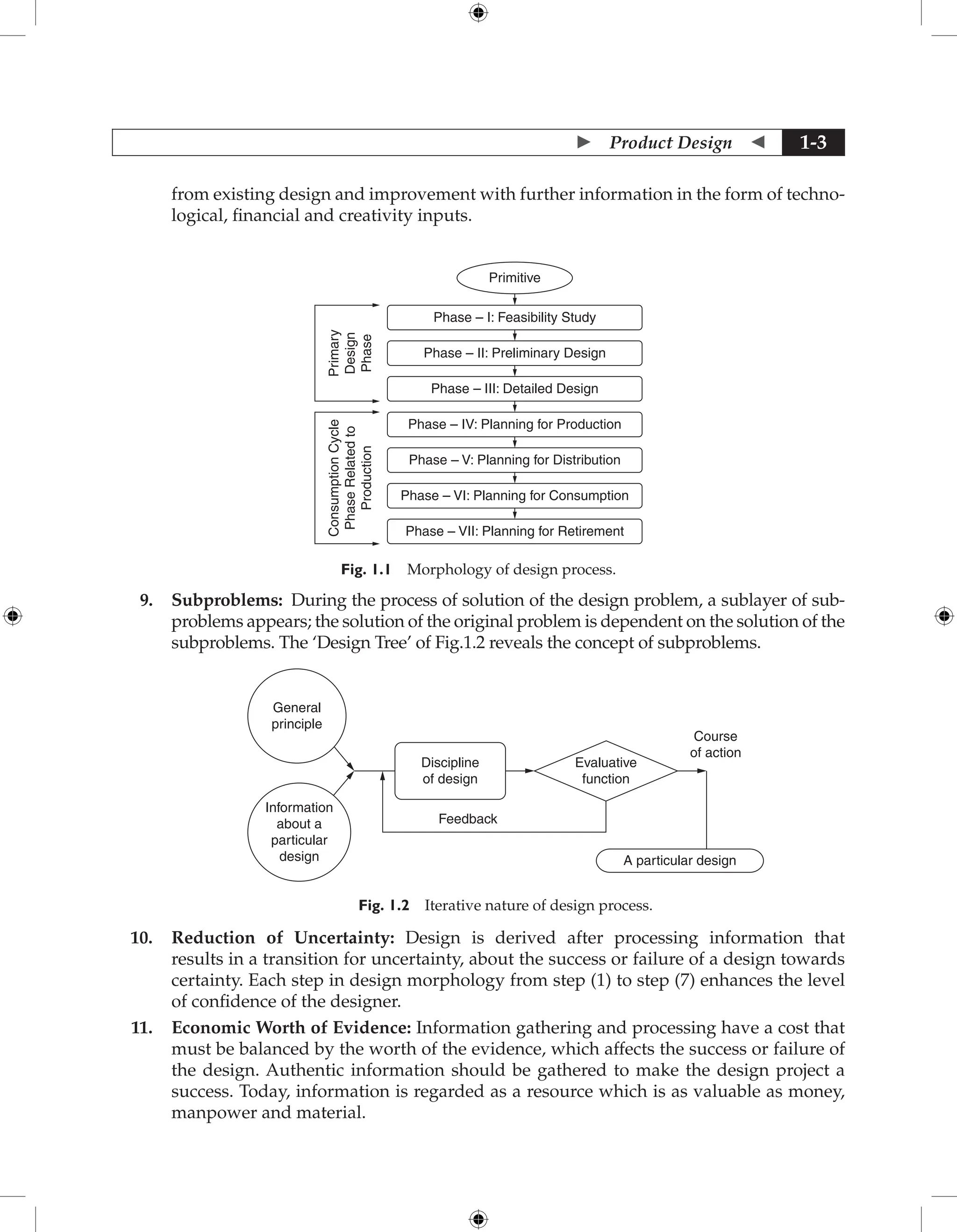
Fig. 1.157 Allowable unit load versus revolutions to failure by flexural fatigue (fluctuating tooth bending
stress). For unfilled, acetal copolymer Celcon gear with steel pinion and initial grease lubrication. For Ex.
19.2, Lu = 182 lb/in at 107
cycles for a 32-pitch gear. (Hoechst Celanese Corp).
Kt = 7000/8800 = 0.80 at 100o
F
(See Table 1.8. Kt = 1.0 for metal gears)
KL = lubrication factor = 1.0 for initially lubricated pair (this case) = 1.5–3.0 for
continuous lubrication
Km = mating material factor = 1.0 for steel pinion, 32 m in rms surface finish or better
with friction coefficient of 0.15
Km = 0.75 for acetal-steel pair with friction coefficient of 0.35
Ks = tooth type factor = Ydes for design gear/Yref for reference gear
where Y = Lewis form factor: Yref = 0.52, 0.64, or 0.69 for 12, 24, or 32 diametral pitch
gears, respectively. Ydes is given in Table 1.10 for full-depth 20o
pressure angle gears. In
this example, with 80 teeth in the acetal gear, Ydes = 0.739 and Ks = 0.739/0.69 = 1.07.
Kg = gear type factor = 1.0 for spur, internal, and helical gears.
Cs = service factor = 0.80 (Table 1.10)
Combining these factors gives the predicted load to failure in 107 cycles from Eq. 2.2:
Lf = (182 × 0.80 × 1.0 × 1.0 × 1.07)/0.80 = 195 lb/in
which is 348% greater than the applied unit load of 56 lb/in.
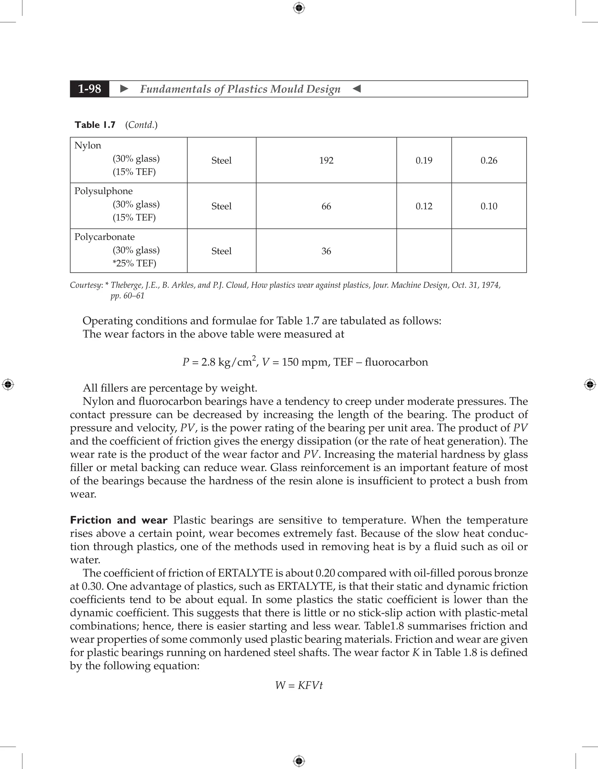
3. Plastic and metal gears generally fail because of wear or pitting associated with com-
pressive fatigue. The contact stress in this example will now be checked against the
allowable contact stress for Celcon. The allowable contact stress Sc for unlubricated
pairs is proportional to the reference value Sc in Fig.1.158 multiplied by the factor Ck,
which is given by
Ck = {0.70/[(1/E1 + 1/E2) cos f sin f ] } 0.5](https://image.slidesharecdn.com/fundamentalsofmoulddesign-231217032858-869d3d7e/75/Fundamentals-of-Mould-Design-lecture-pdf-114-2048.jpg)
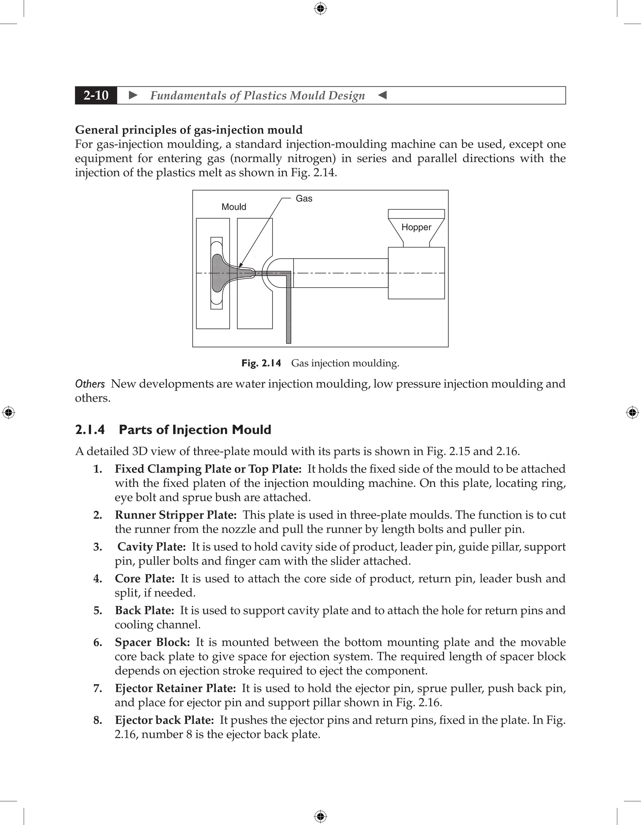
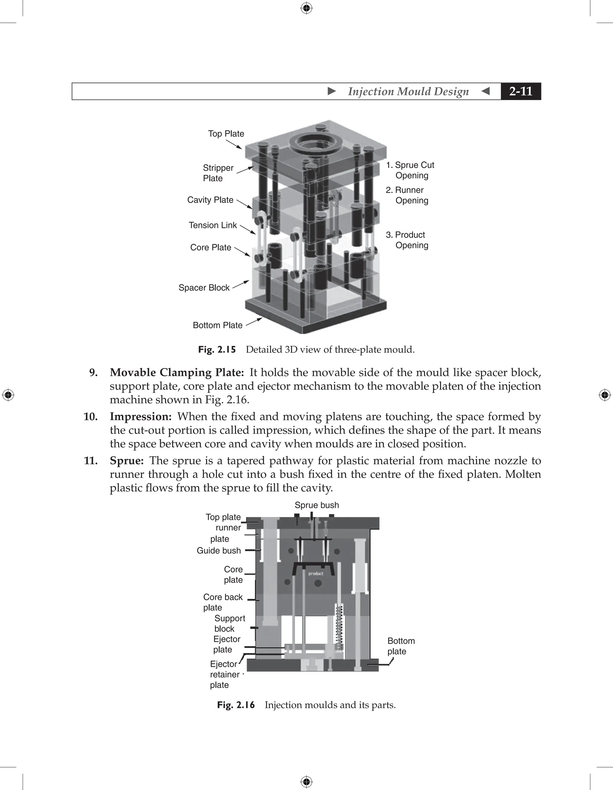
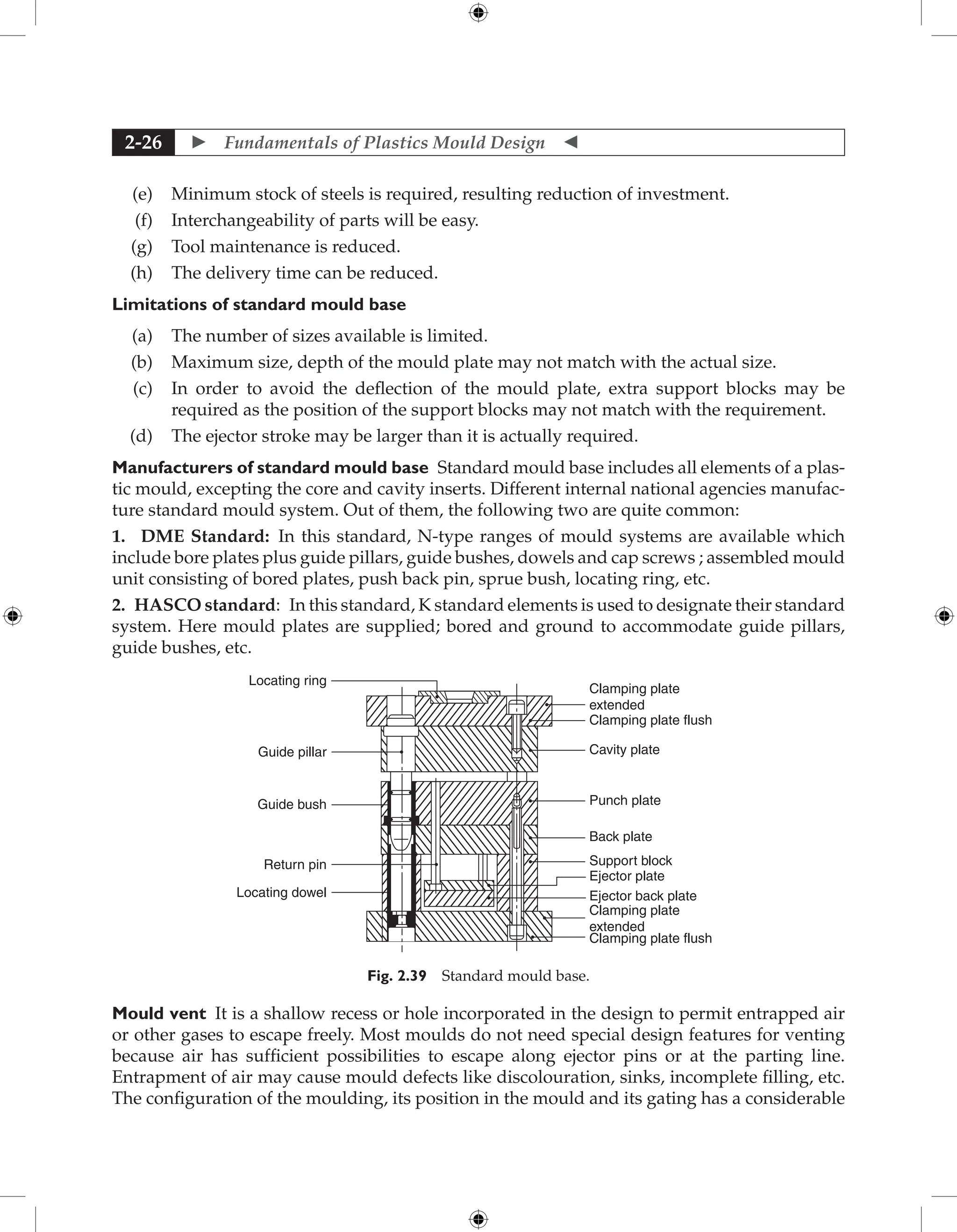
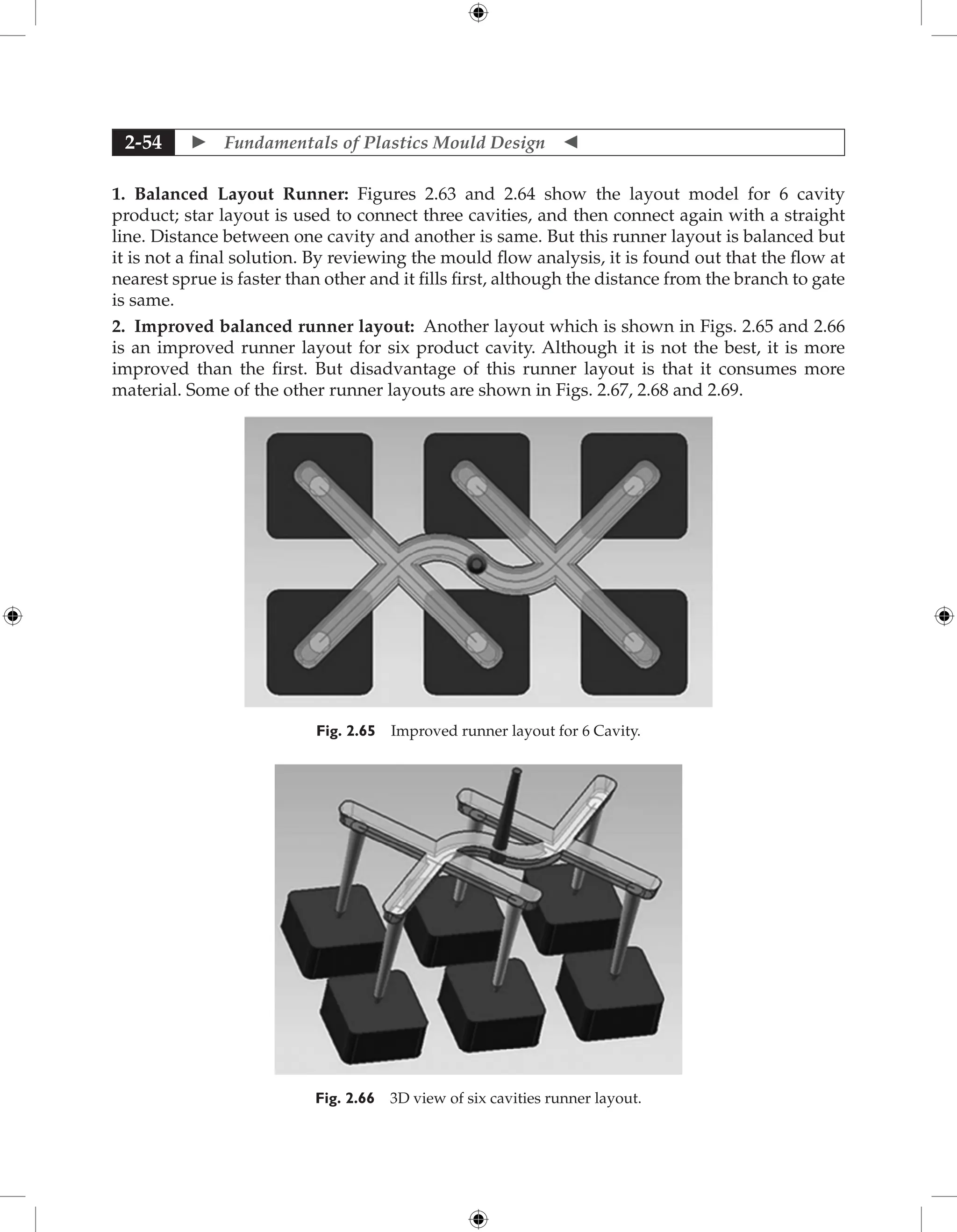
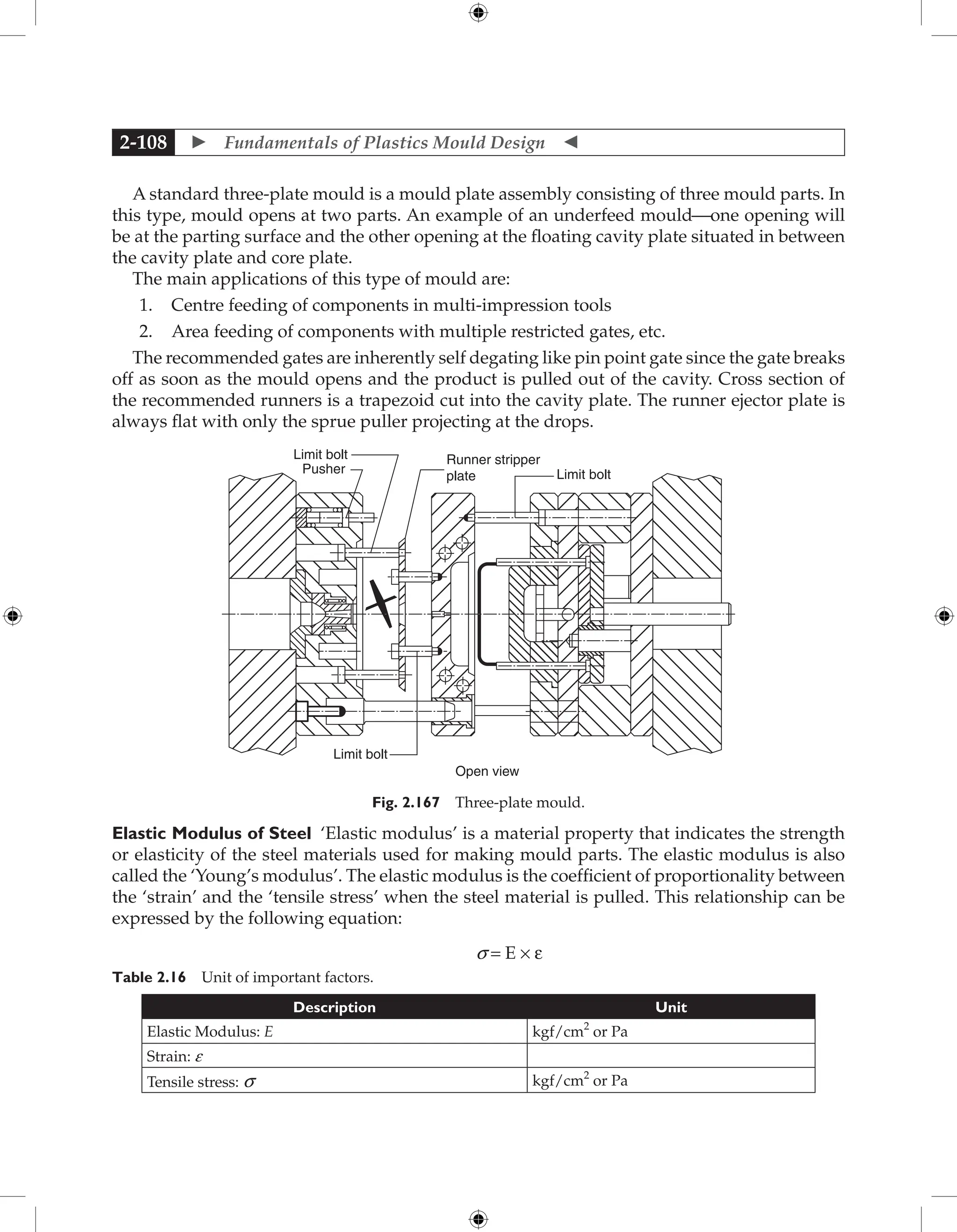
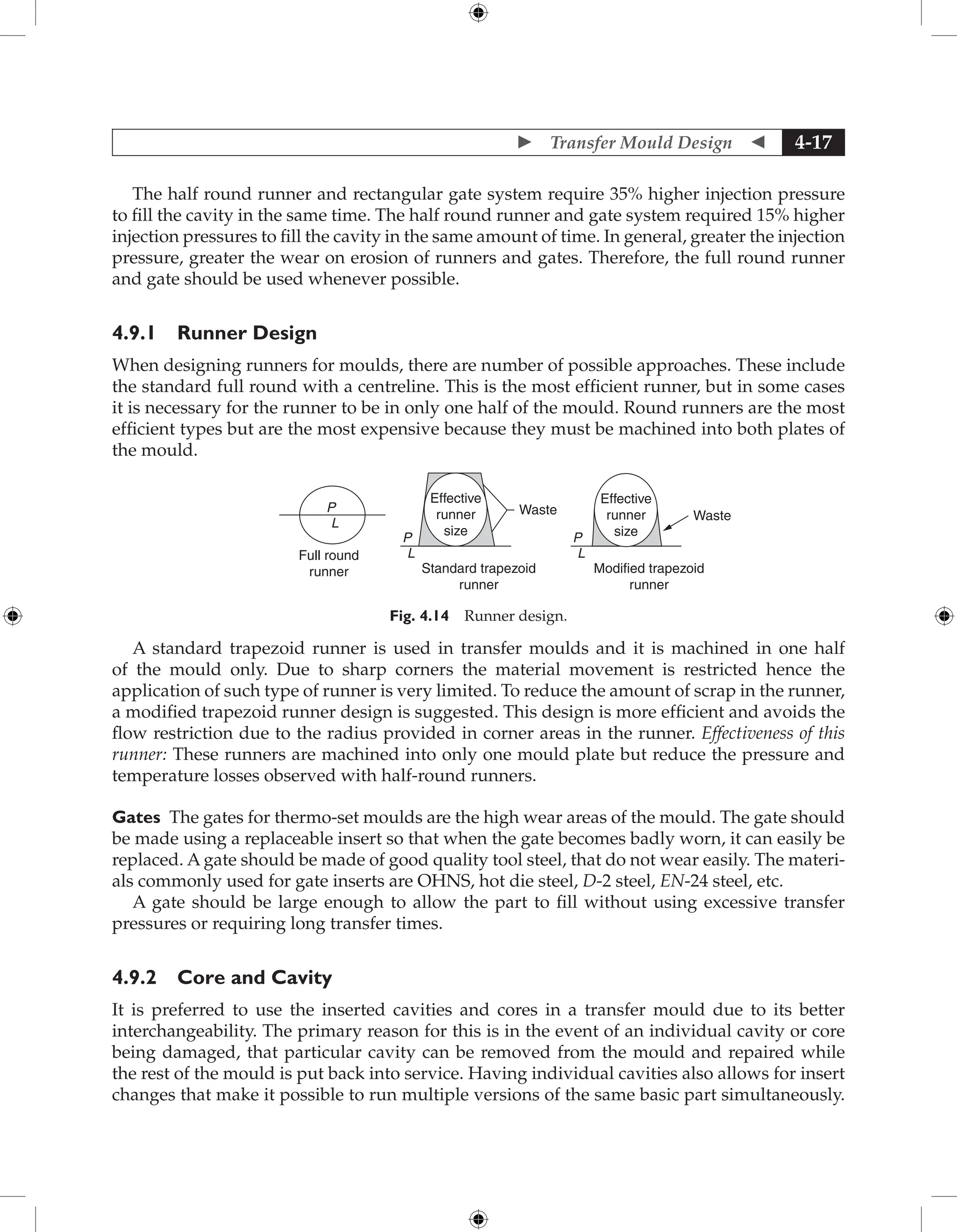
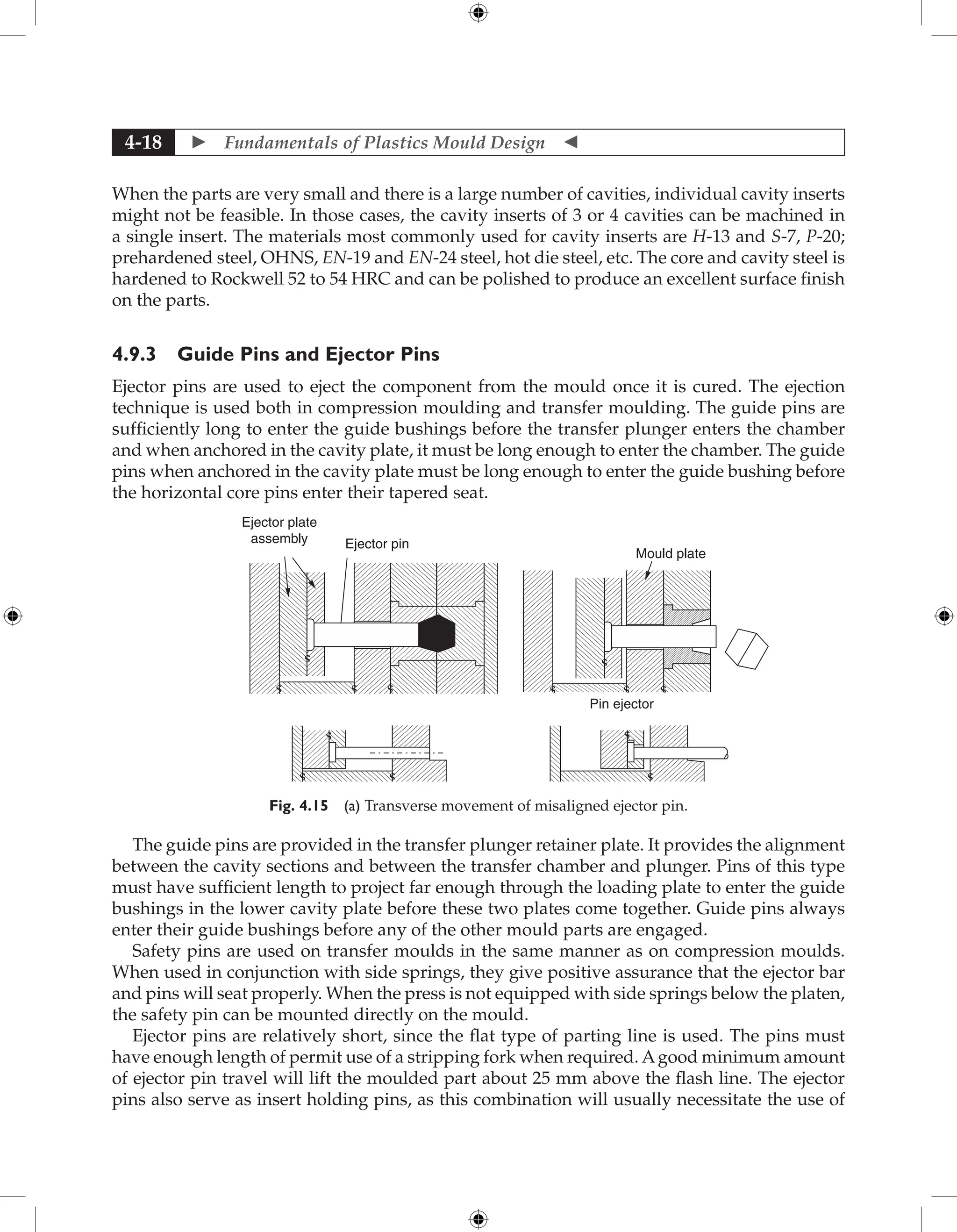
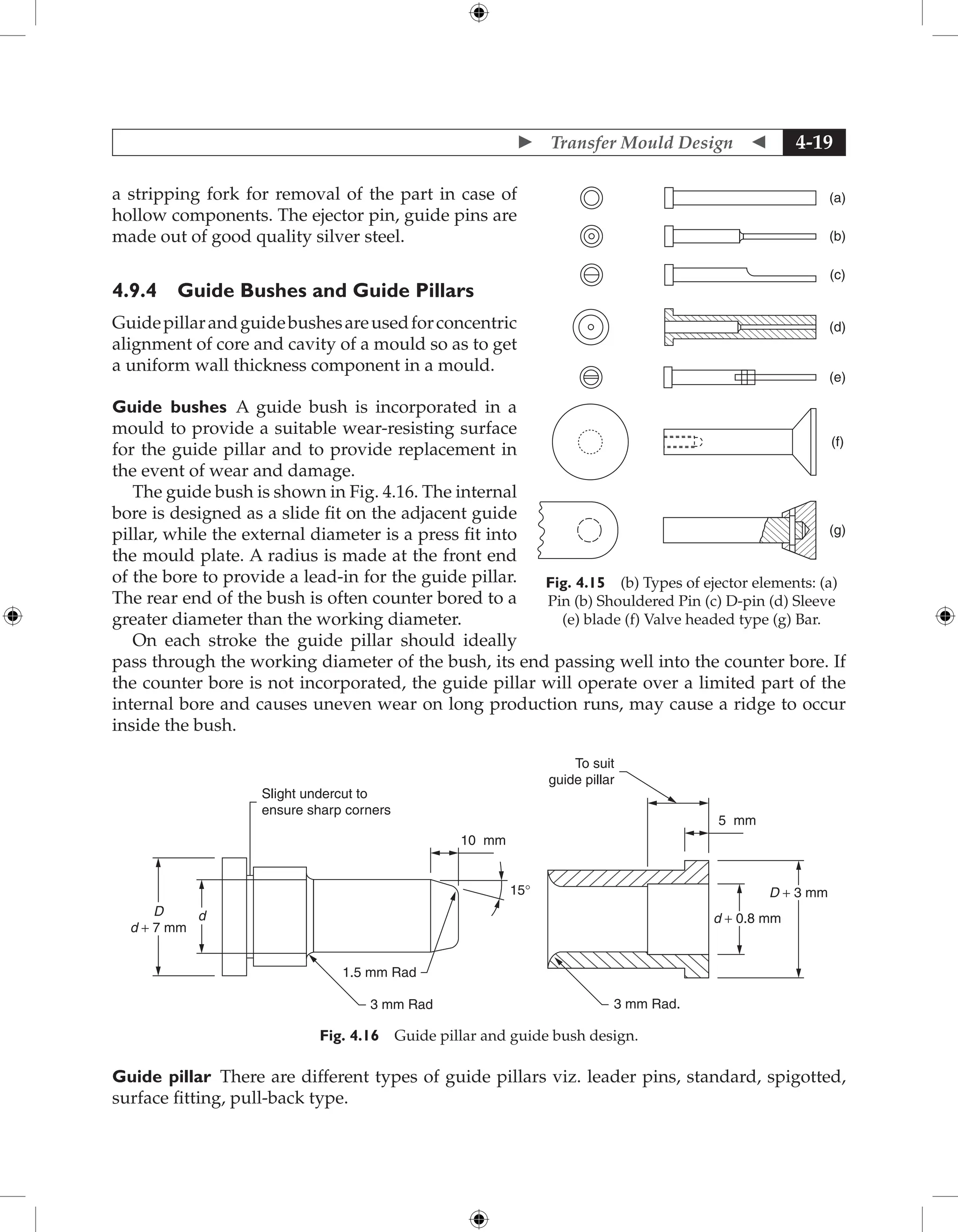
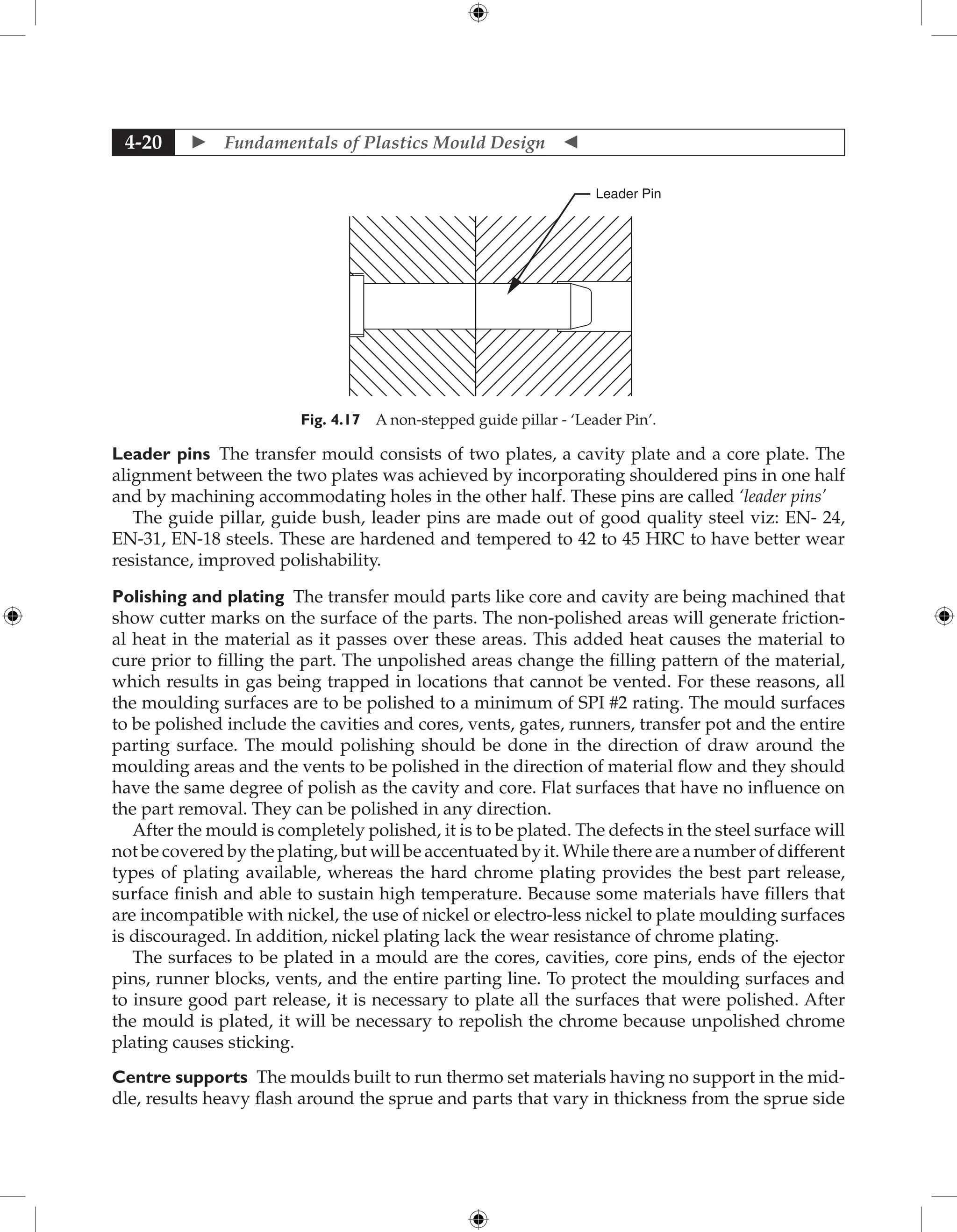
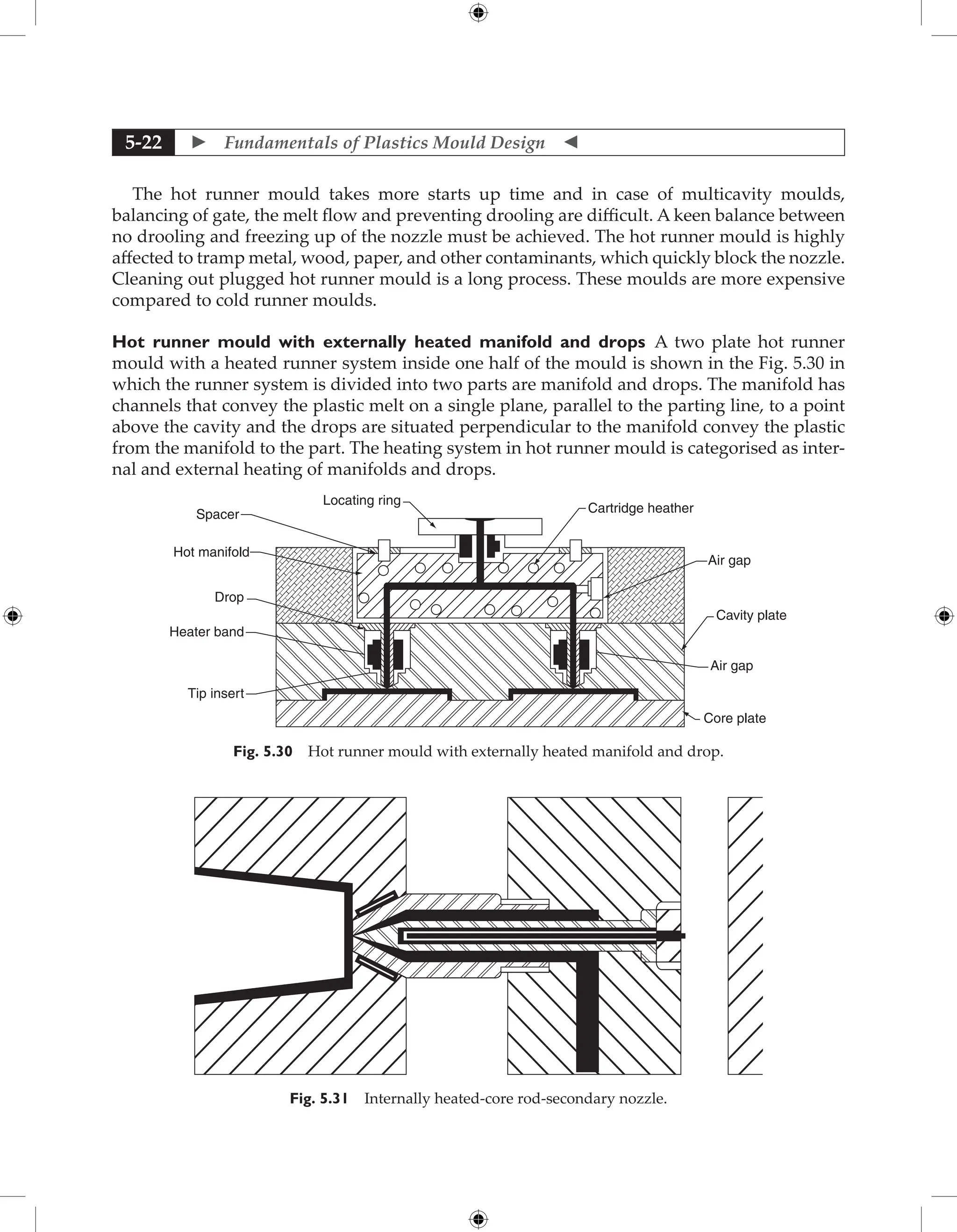
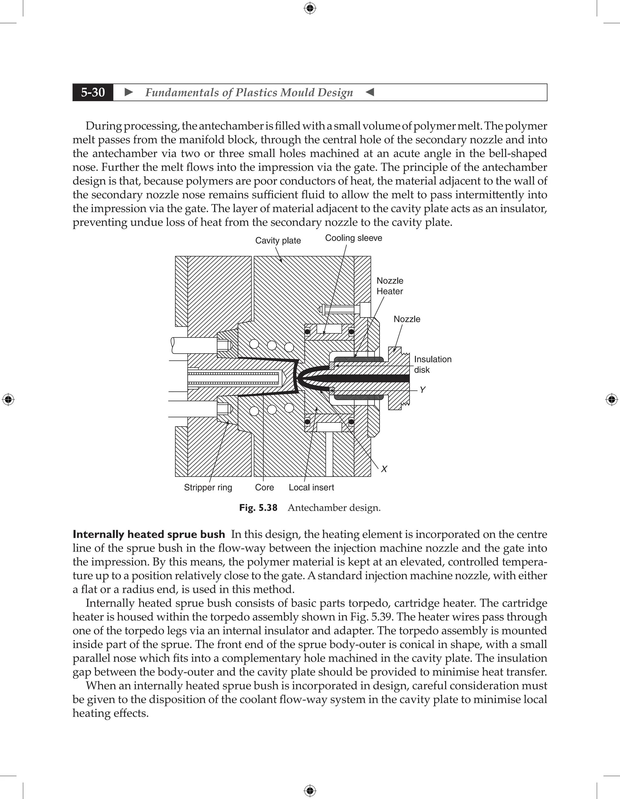
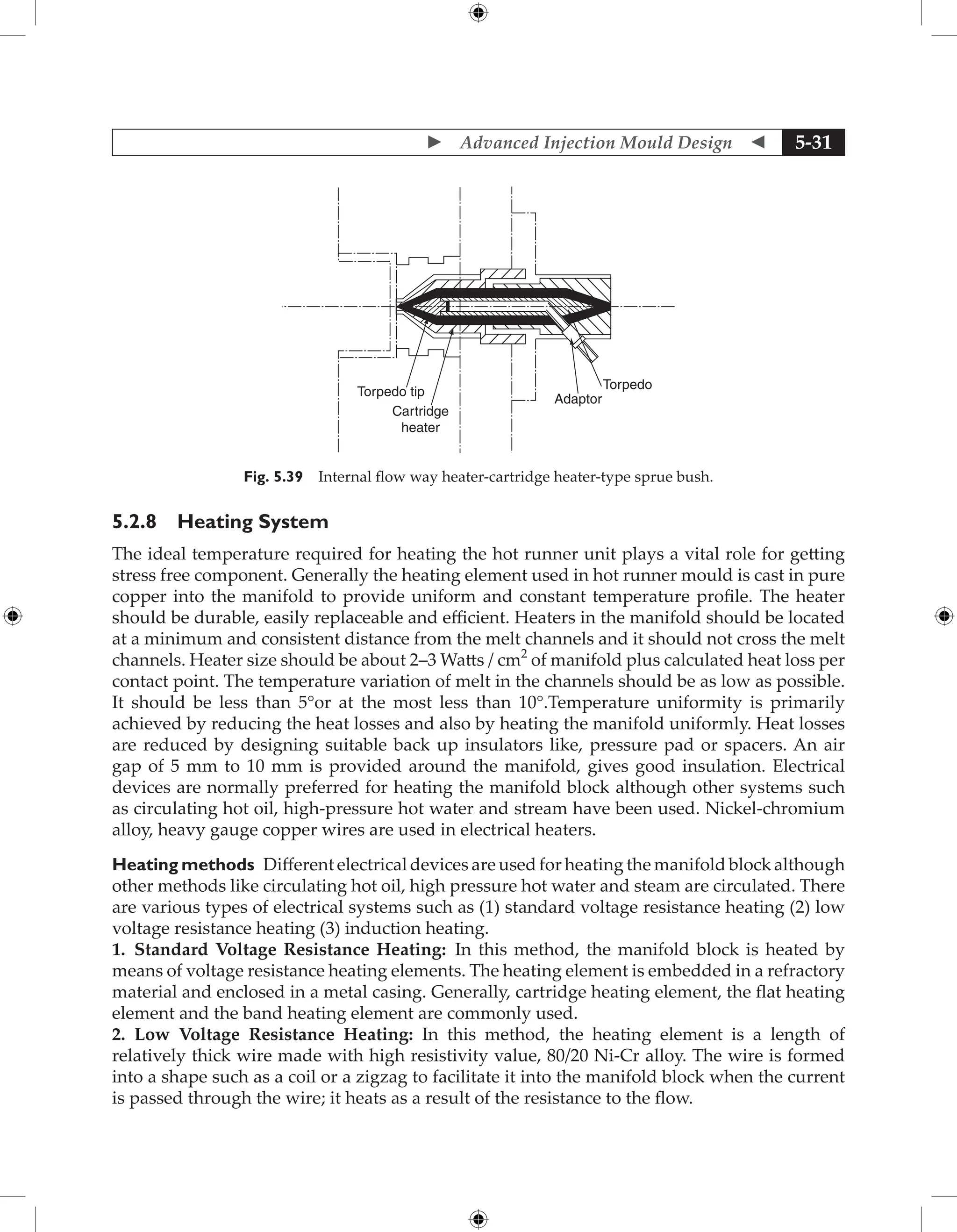
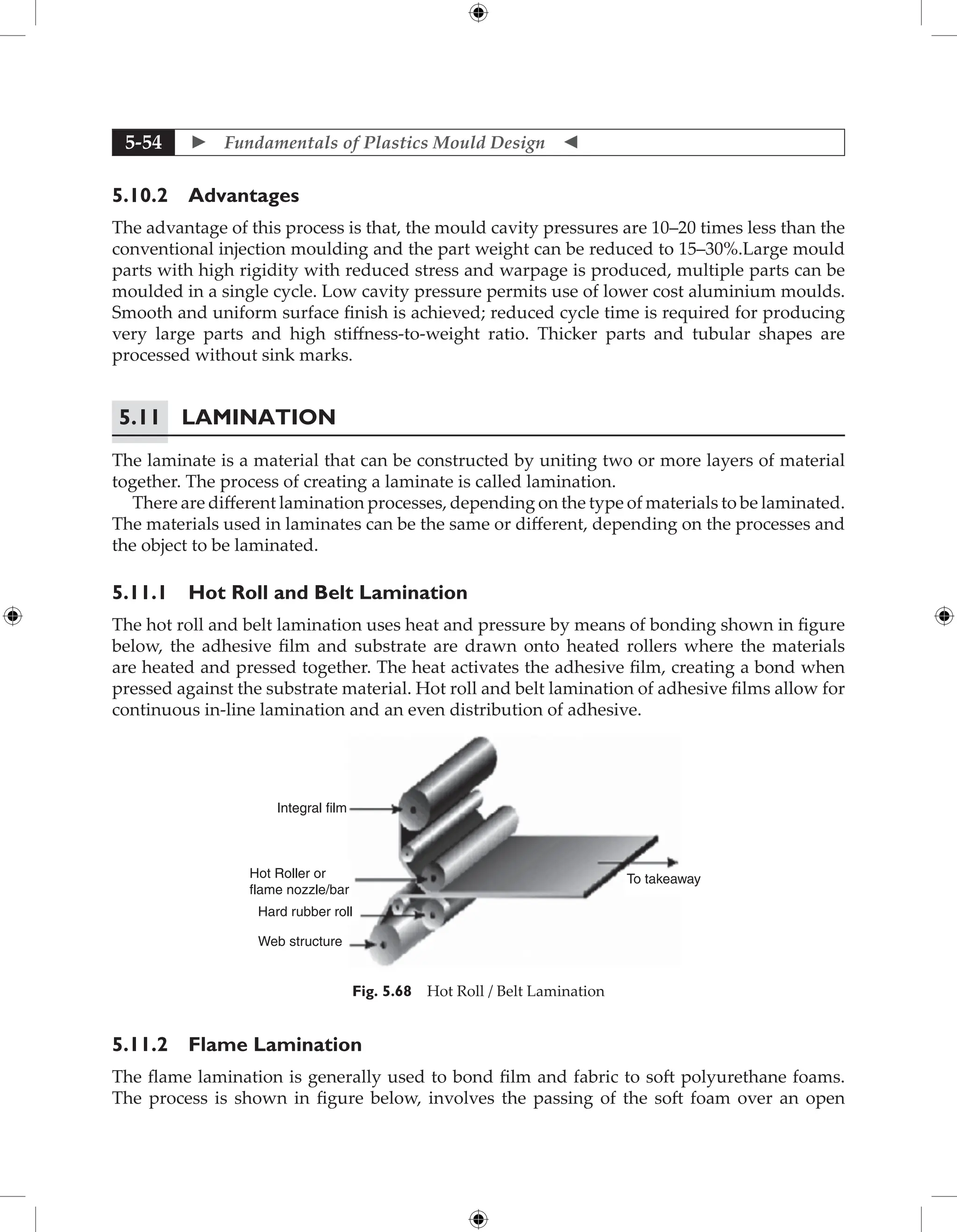
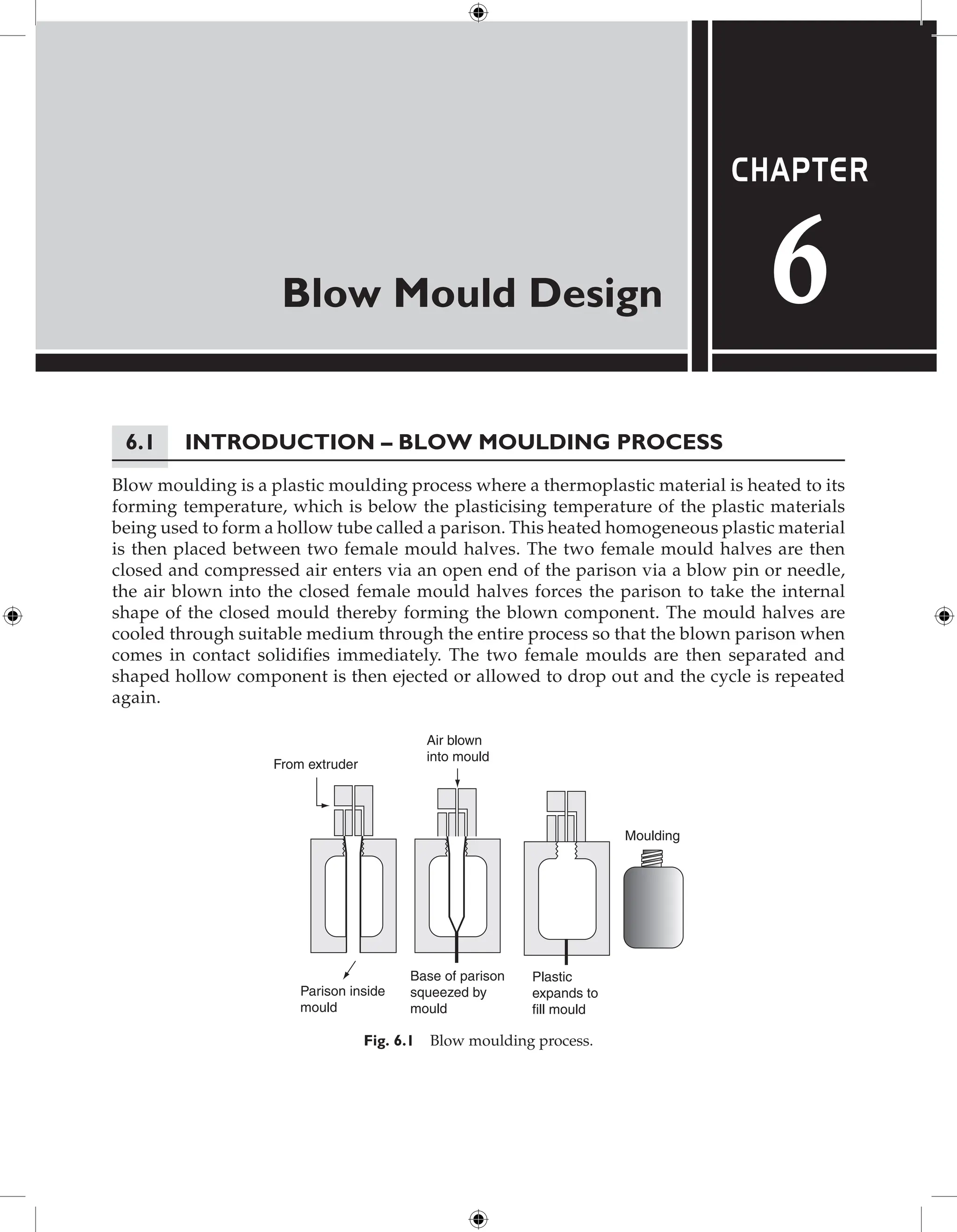
![ Fundamentals of Plastics Mould Design
1-102
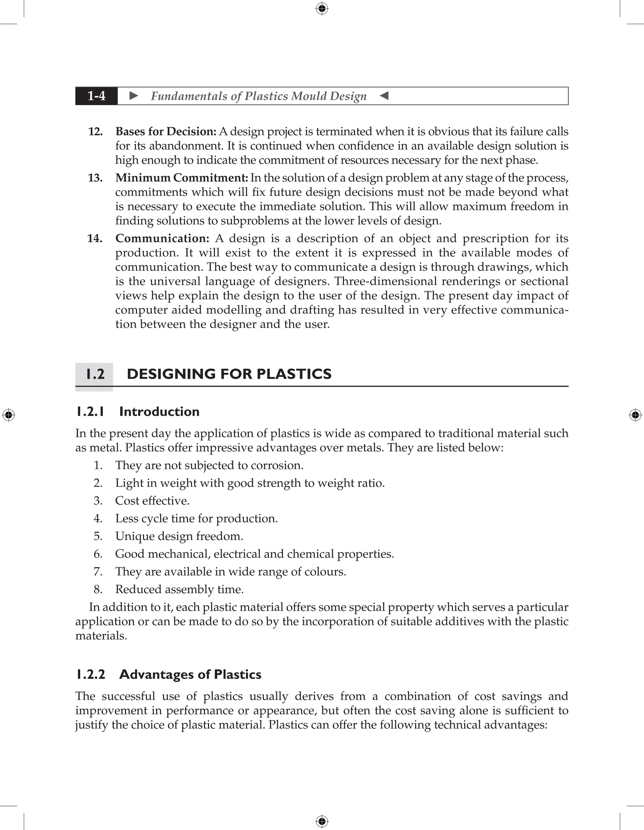
E1 and E2 are Young’s moduli for the mating materials, and f is the pressure angle.
E1=29×106 psi for the steel pinion. E2=315,000 psi for the Celcon gear from Table 1.11 at
100F. Equation 2.3 gives Ck = 824. Figure 1.158 gives Sc - 2800 at 107 cycles. Therefore,
the allowable contact stress is
Sac = Sc Ck/639 = 2800 × 824/639 = 3610 psi
The applied contact stress is given by
sc = {[Lt Ck (m + 1)]/Dp m}0.5 = 9550 psi
Since the applied sc is considerably larger than the allowable sc, this design is not feasible.
The simplest fix is to increase gear face width from 0.300 to at least 2.10 in. The problem
then is that the pinion face width is about four times its pitch diameter, which will require
careful shaft alignment. A better solution might be to use a Celcon–Celcon pair. The advantage
is the much greater accommodation of plastic-plastic gear pairs to tooth misalignment, which
allows design of gears with higher face width/pitch diameter ratios.
Table 1.9 Tensile yield strength versus temperature for Celcon acetal copolymer*.
Temperature o
C –18 10 38 66 93 100
Yield strength (MPa) 83 67 50 38 29 28
* Celcon M90, unfilled virgin resin (Hoechst Celanese Corp.).
Table 1.10 Lewis form factor Y for 20o
pressure angle, full depth gear teeth.
Number
of teeth
12 14 16 18 20 24 30 38 50 75 100 300
Y 0.415 0.468 0.500 0.520 0.544 0.571 0.605 0.650 0.696 0.734 0.758 0.802
73°F (23°C)
20° Pressure Angle
Celcon Gear and Pinion
Unlubricated
Pitch Line Velocity = 2330 FPM (710m/min.)
Curve reduced 25% form Experimental
Data (becuase data taken under laboratory
conditions)
104
2000
(140)
3000
(210)
4000
(280)
5000
(350)
6000
(420)
7000
(490)
105
106
NUMBER OF REVOLUTINS TO GEAR FAILURE
MAXIMUM
ALLOWABLE
CONTACT
STRESS
Sc,
psi
(KG/cm
2
)
107
108
Fig. 1.158 Allowable surface contact stress versus number of gear revolutions to failure by surface wear
for unfilled Celcon (Hoechst Celanese Corp.).](https://image.slidesharecdn.com/fundamentalsofmoulddesign-231217032858-869d3d7e/75/Fundamentals-of-Mould-Design-lecture-pdf-115-2048.jpg)


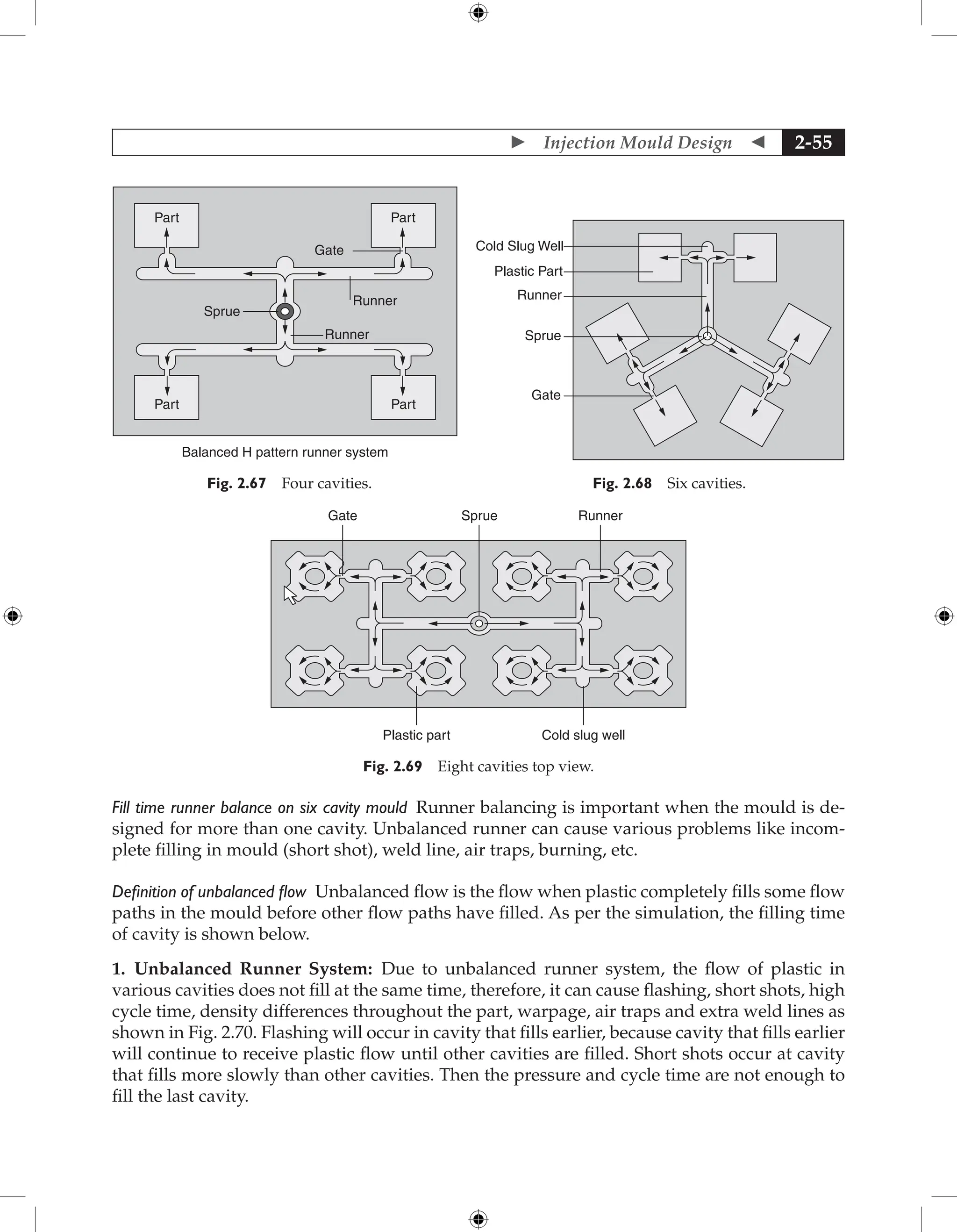
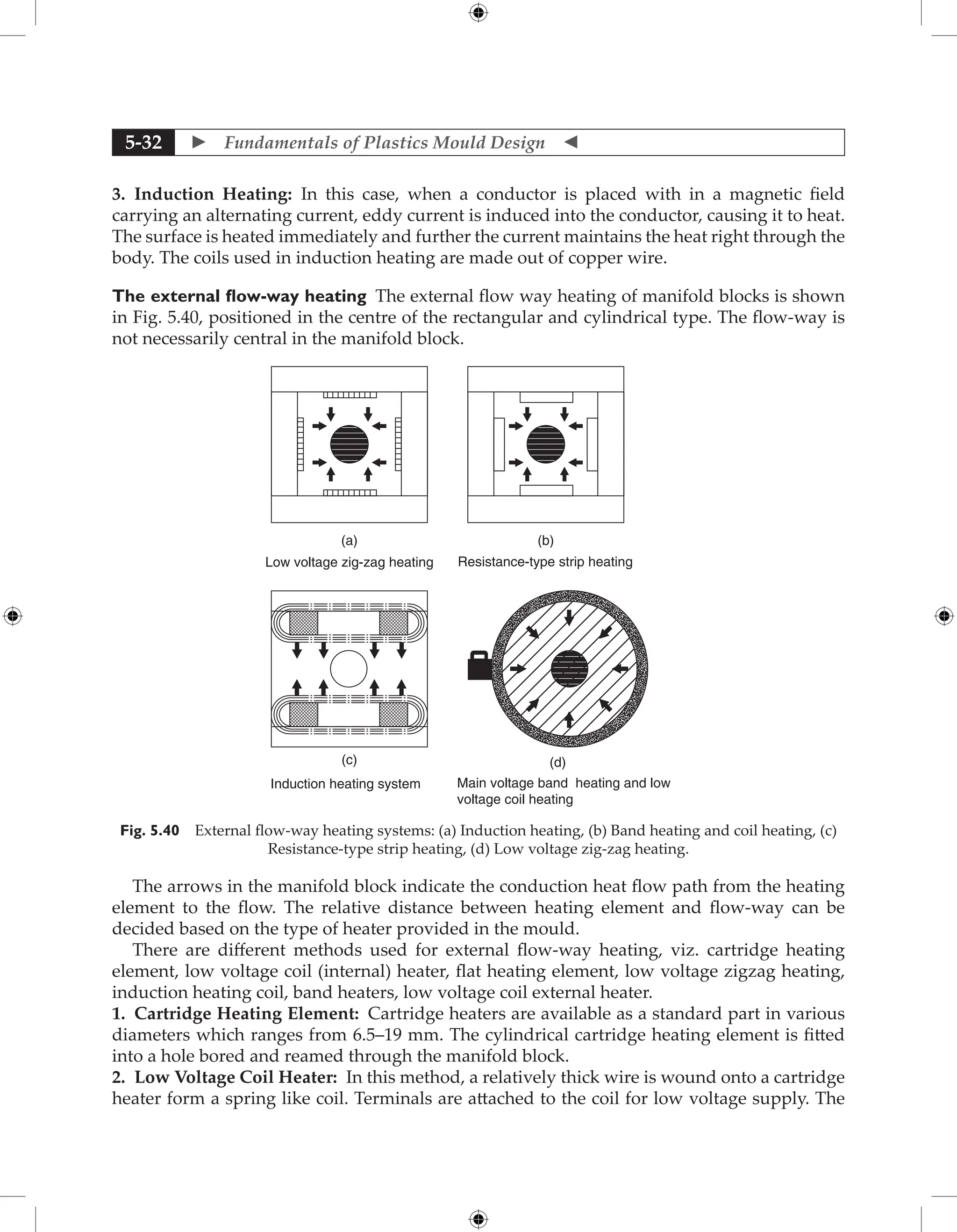
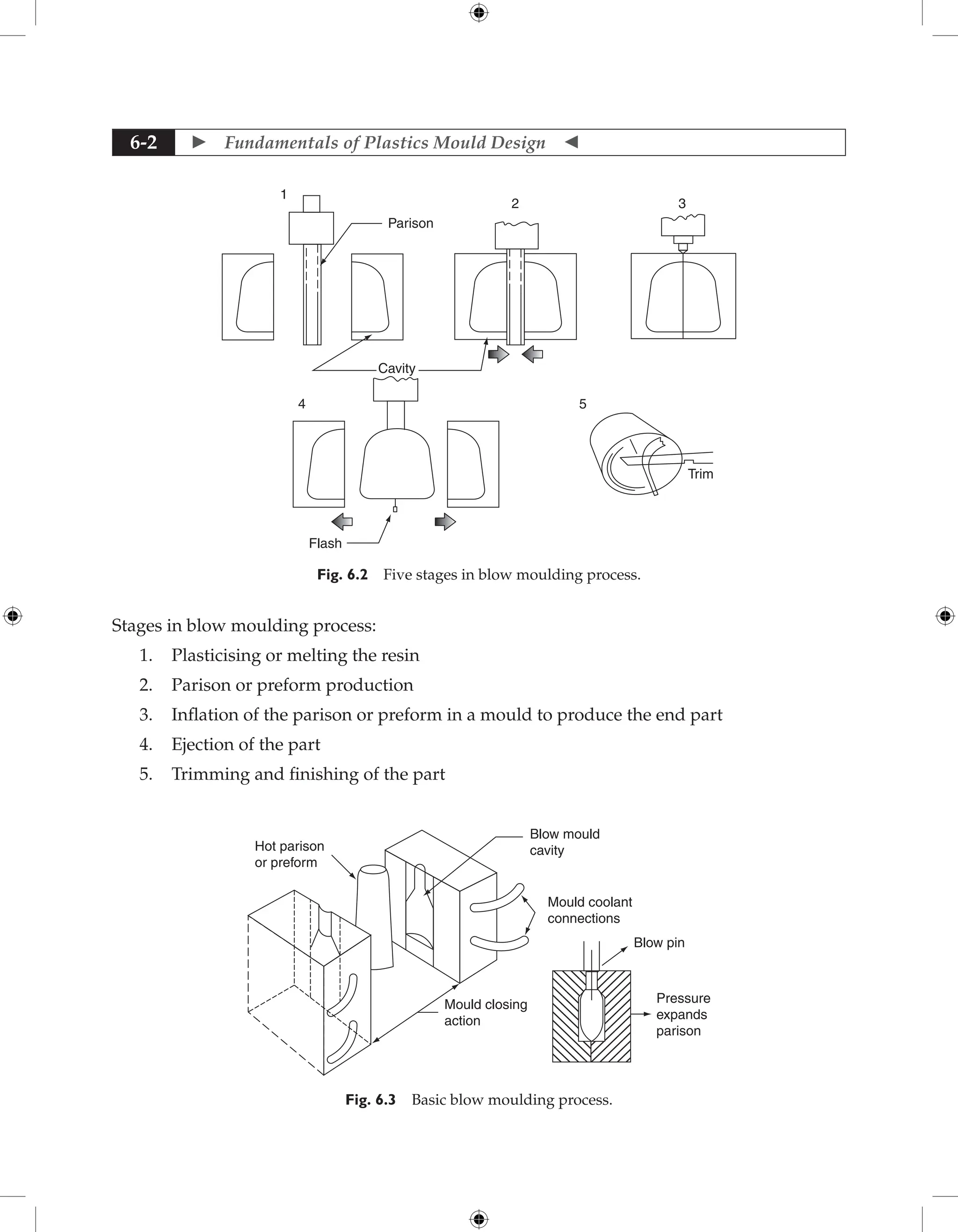
![ Fundamentals of Plastics Mould Design
2-56
[sec]
0
0.09
0.18
0.26
0.35
0.44
0.53
0.62
0.71
0.79
20 mm
0.88
.55
.16
.22
Z
Y
X
Fill Time
Fig. 2.70 Unbalanced runner system.
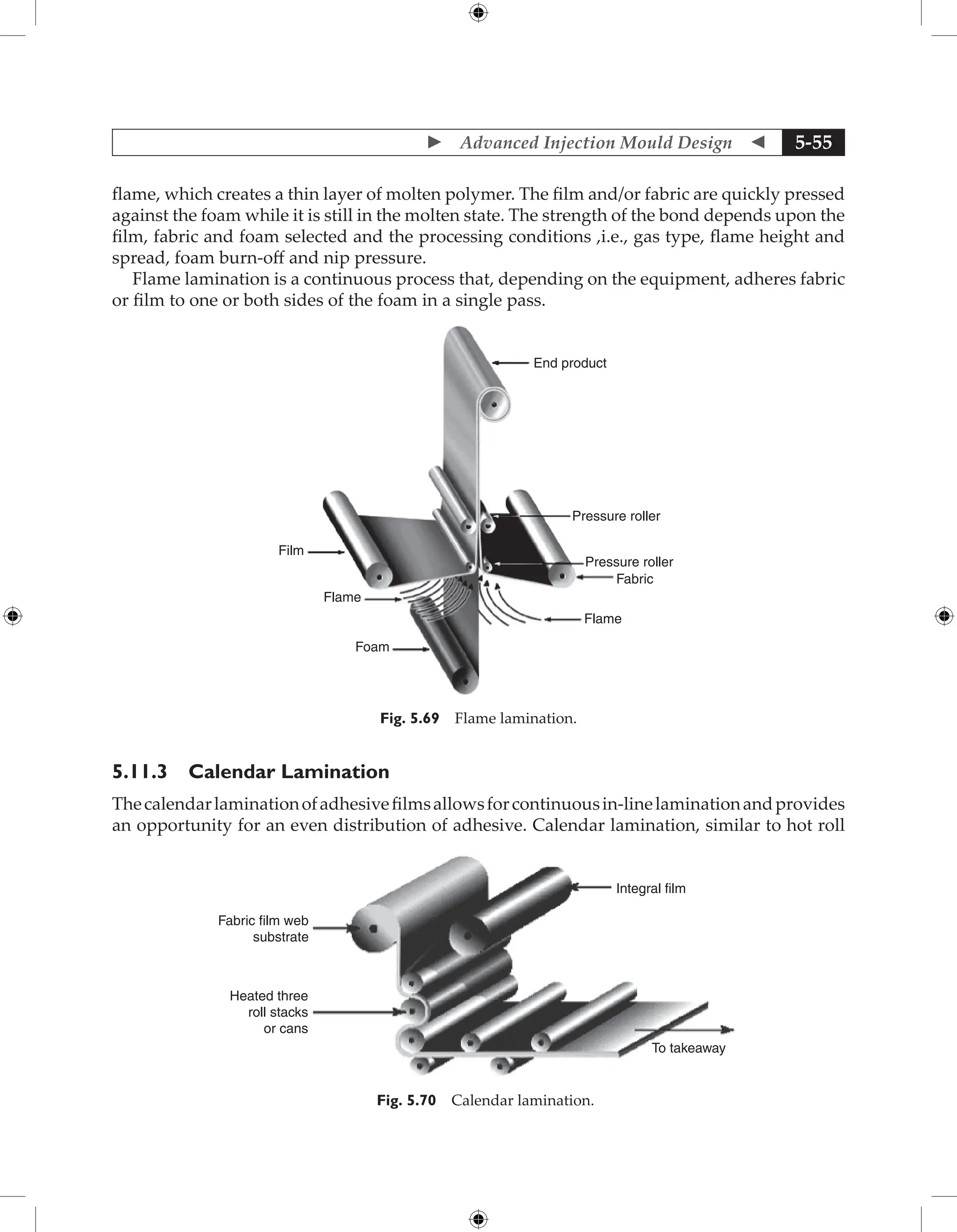
2. Balanced Runner of Six Cavities: Although this runner layout is not the best solution but
it is better for six cavities layout as in this layout the fill time is same for all the six cavities as
shown in Fig. 2.71 and flow is better.
[sec]
Fill Time
0
0.11
0.21
0.32
0.42
0.53
0.64
0.74
0.85
0.96
1.06
126
161
−159
Z
Y
X
20 mm
4
5
6
3
2
1
Fig. 2.71 Filling time result.
Runner system an effective part of the system Since the design of the runner system has
large effect on moulding quality, moulding efficiency, cycle time, cooling time and other factor,
so it is important factor of the mould.](https://image.slidesharecdn.com/fundamentalsofmoulddesign-231217032858-869d3d7e/75/Fundamentals-of-Mould-Design-lecture-pdf-251-2048.jpg)
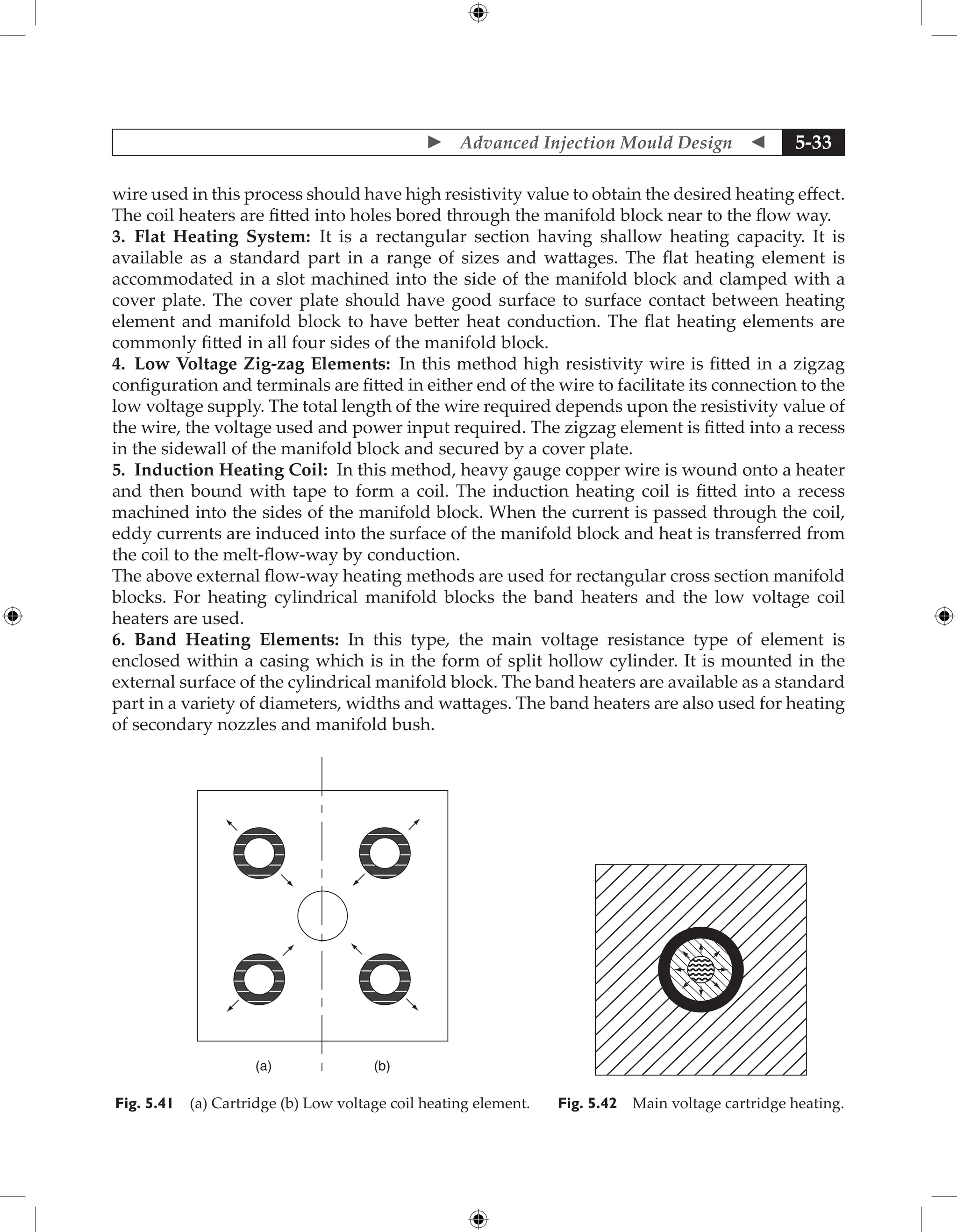
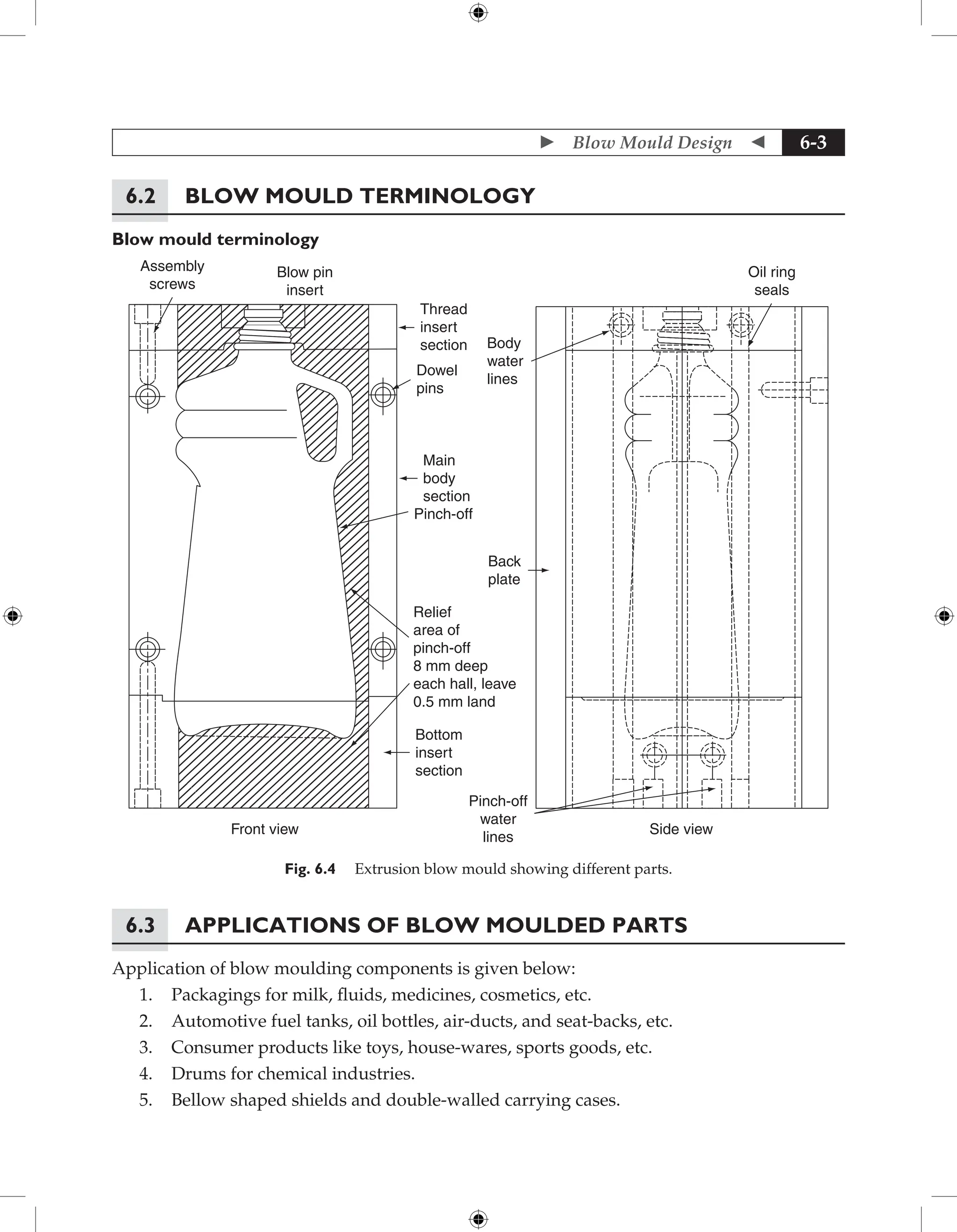
![ Fundamentals of Plastics Mould Design
2-74
Fig. 2.115 Assembly of spacer block.
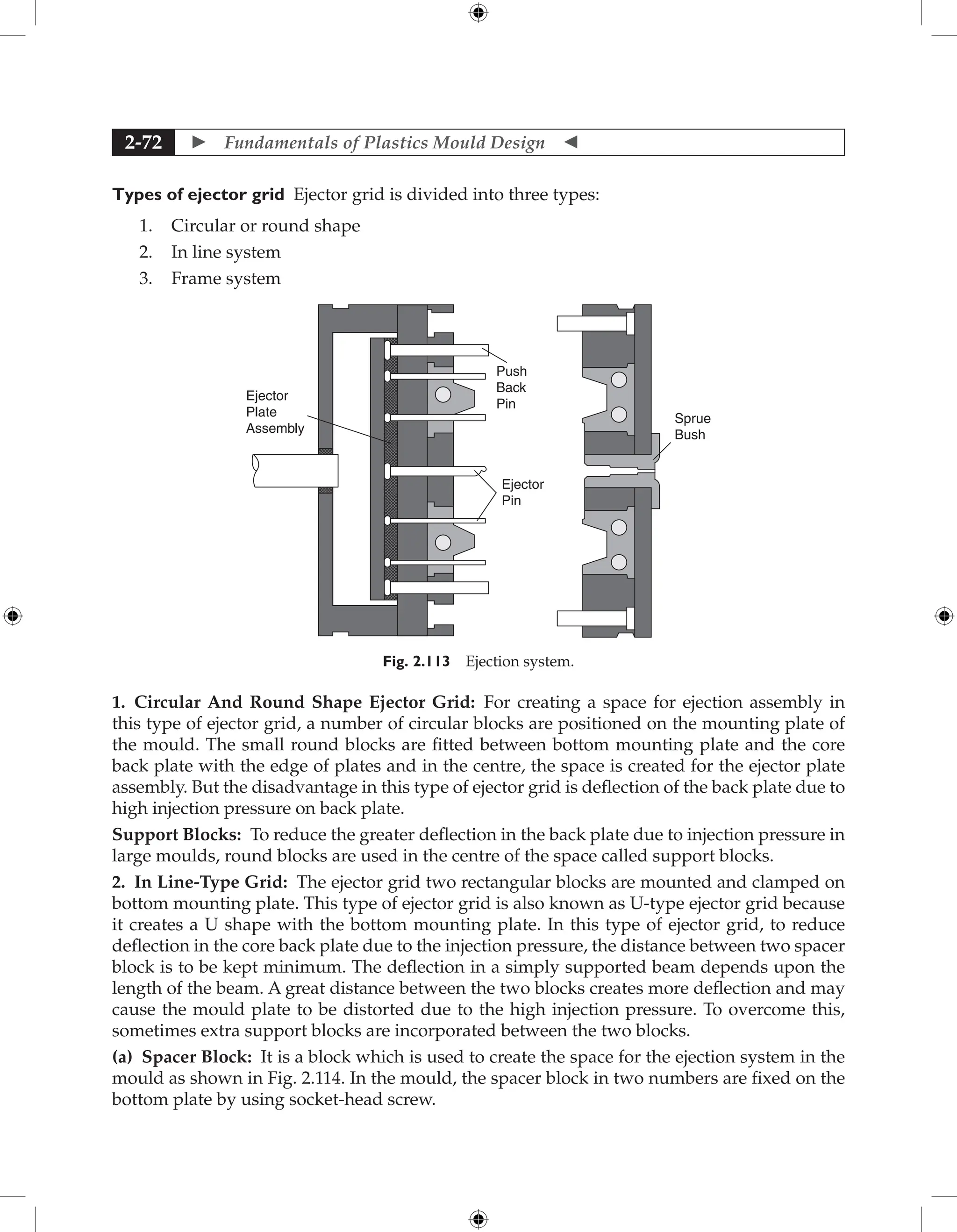
3. Frame Type Grid: It is the type of in line ejector grid except mounting of four numbers of spacer
blocks.Inthistypeofejectorgrid,completeframeismachinedoutsideandfittedwiththemounting
plate. Because of complete frame it creates one boundary for the ejection system. As per the design
of frame, the grid can be designed as rectangular, square or round type of frame ejector grid.
The main advantages of this type of ejector grid are:
(a) Good support to the back plate from all four directions.
(b) Deflection problem can be solved up to a certain level.
(c) Manufacturing cost is less.
(d) The ejection system is completely covered by one boundary, thus it prevents outside
particle to enter the system.
On the basis of shape, the frame grid is further divided as per the shape:
1. Rectangular Type: The blocks are placed as the shape of rectangle called spacer
block.
2. Square Type: The frame is machined as the shape of square called square type grid.
3. Round Type: The blocks are machined in the round shape or well type called round
type grid.
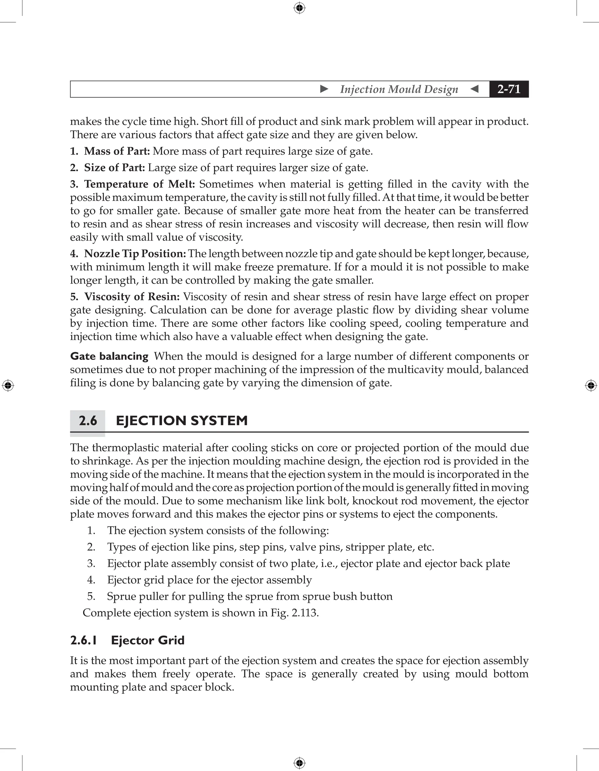
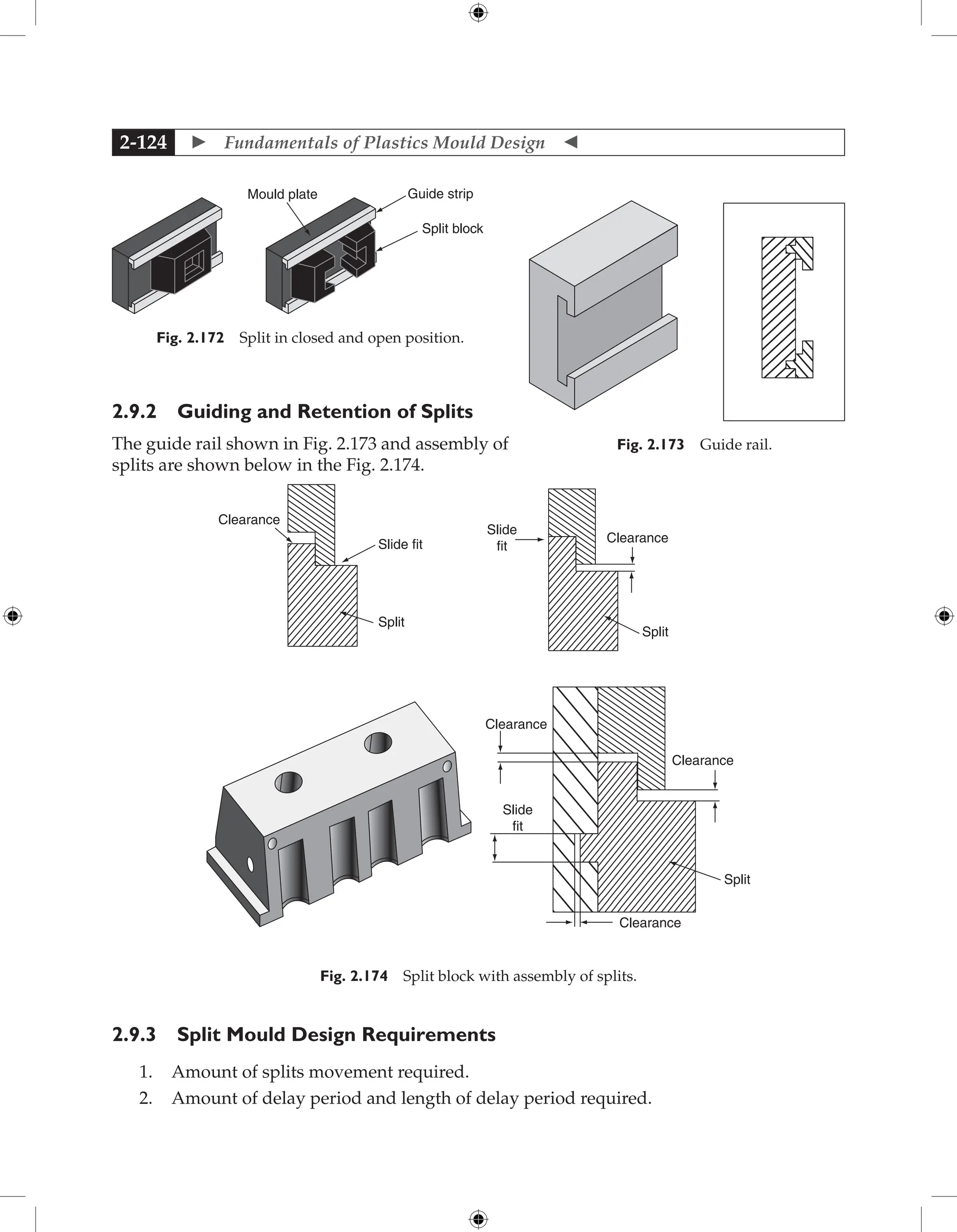
2.6.2 Ejector Plate Assembly
It is that part of the mould to which the ejector element is fitted. It normally consists of an
ejector plate, retaining plate and ejector rod as shown in Fig. 2.115.
Ejector plate It is a steel plate in which the ejector system like ejector [pin, valve, step pin] is
incorporated. The force is applied from the machine moving half to this plate for transmitting](https://image.slidesharecdn.com/fundamentalsofmoulddesign-231217032858-869d3d7e/75/Fundamentals-of-Mould-Design-lecture-pdf-269-2048.jpg)

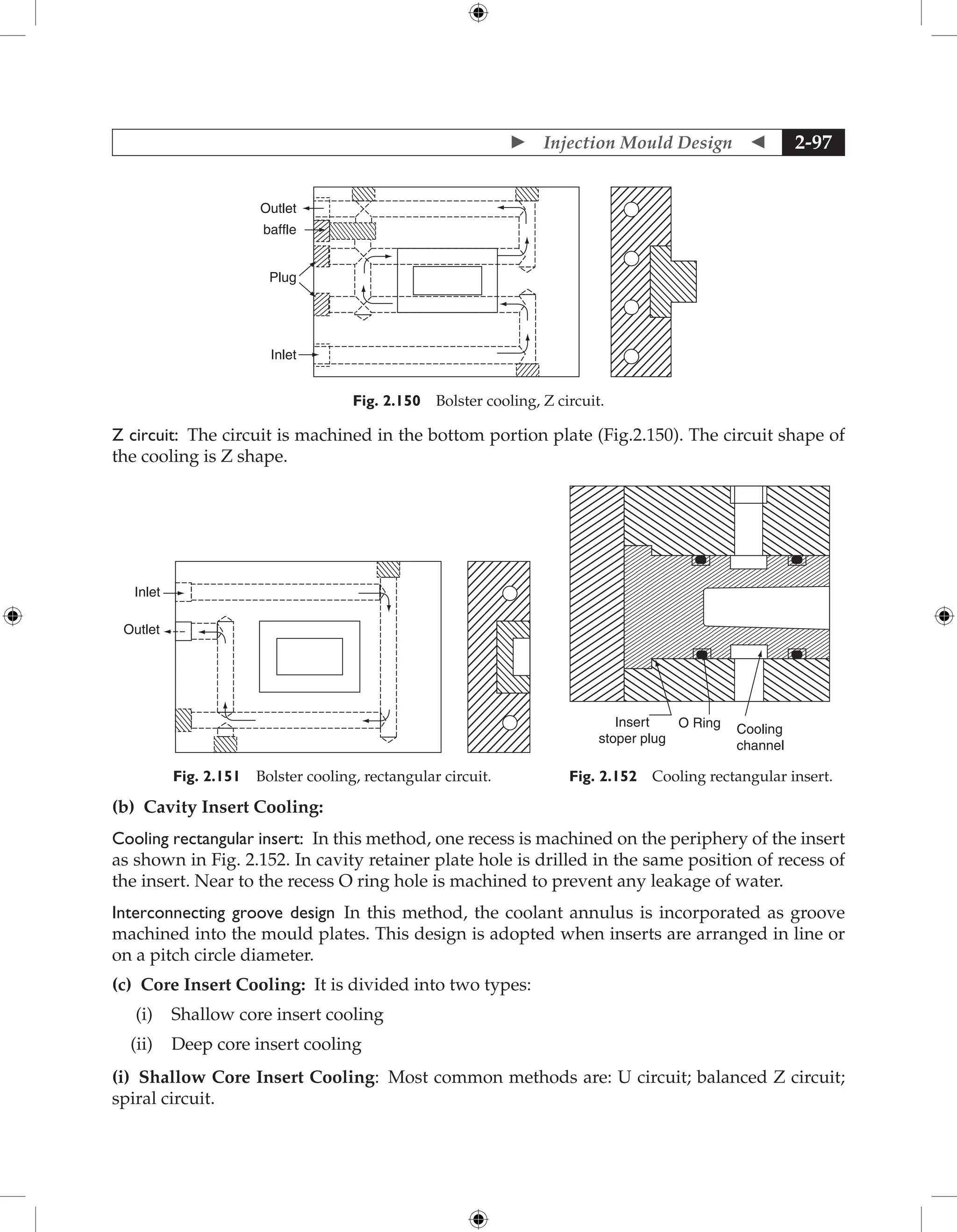
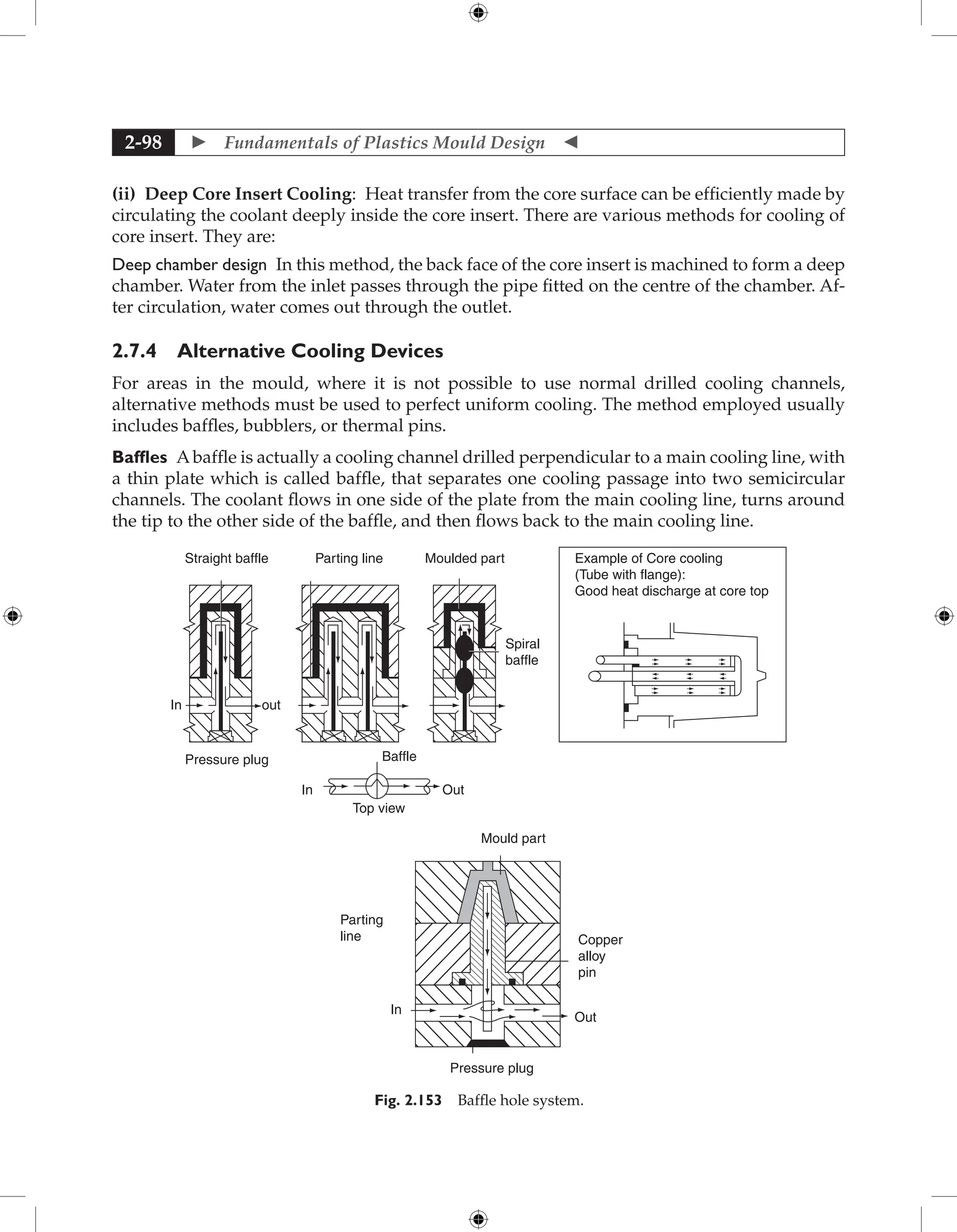
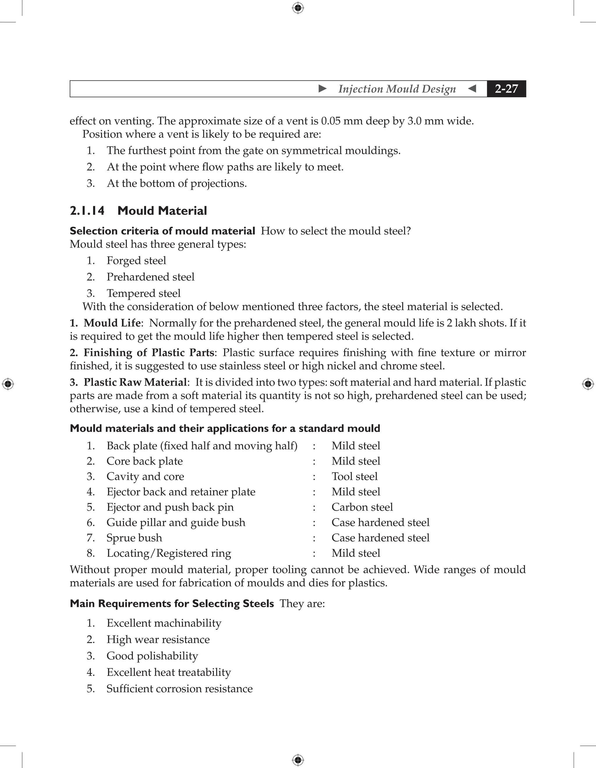
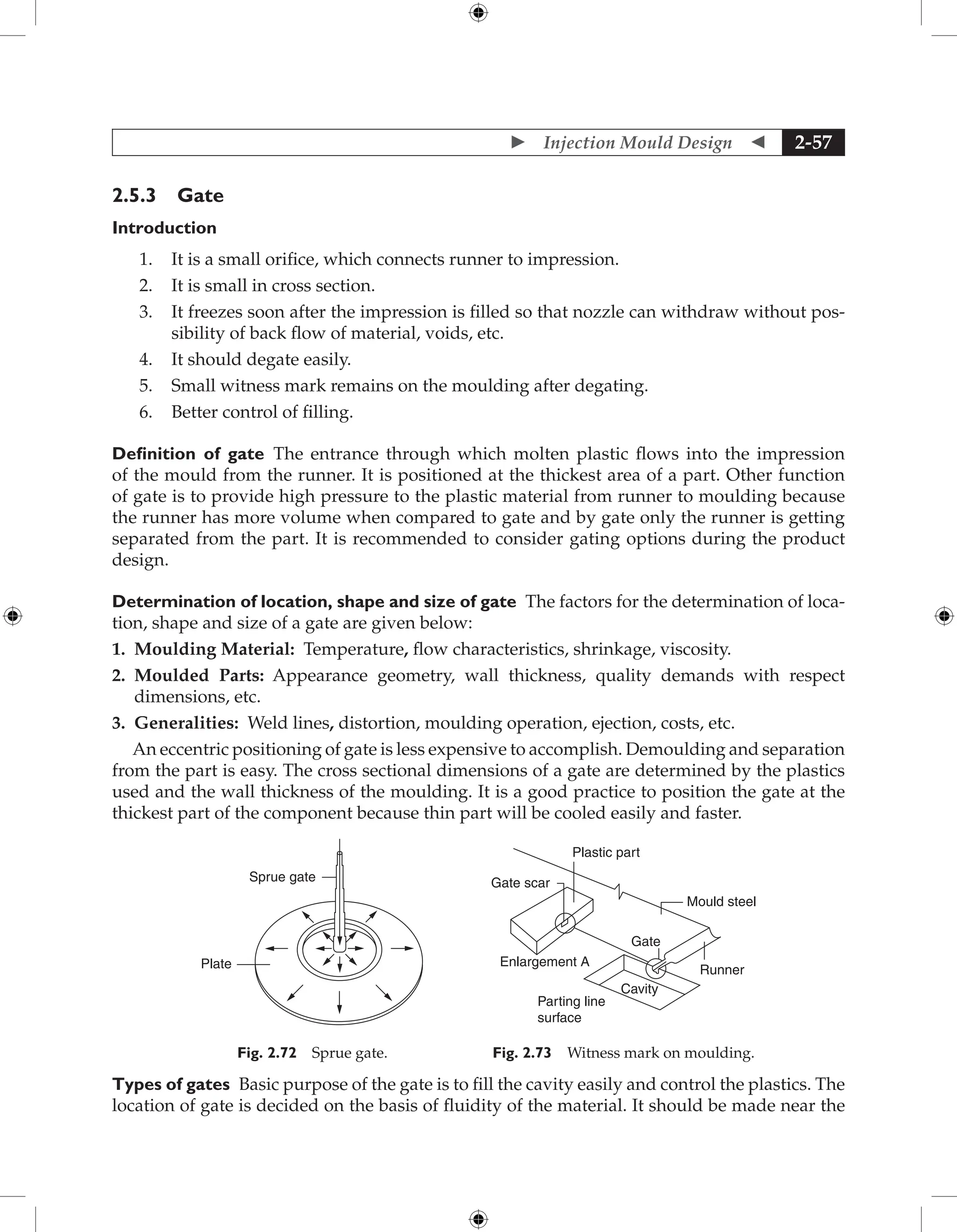
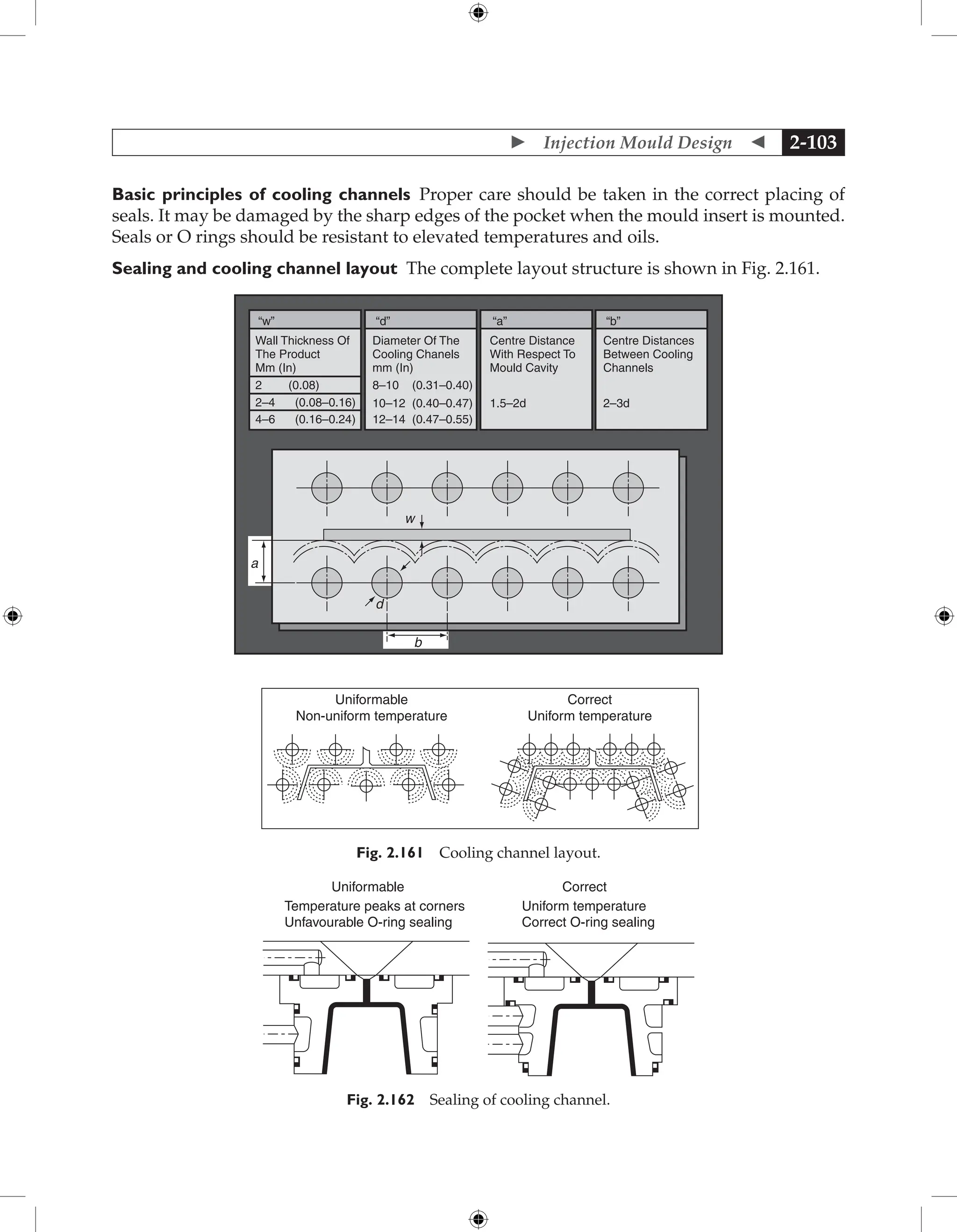
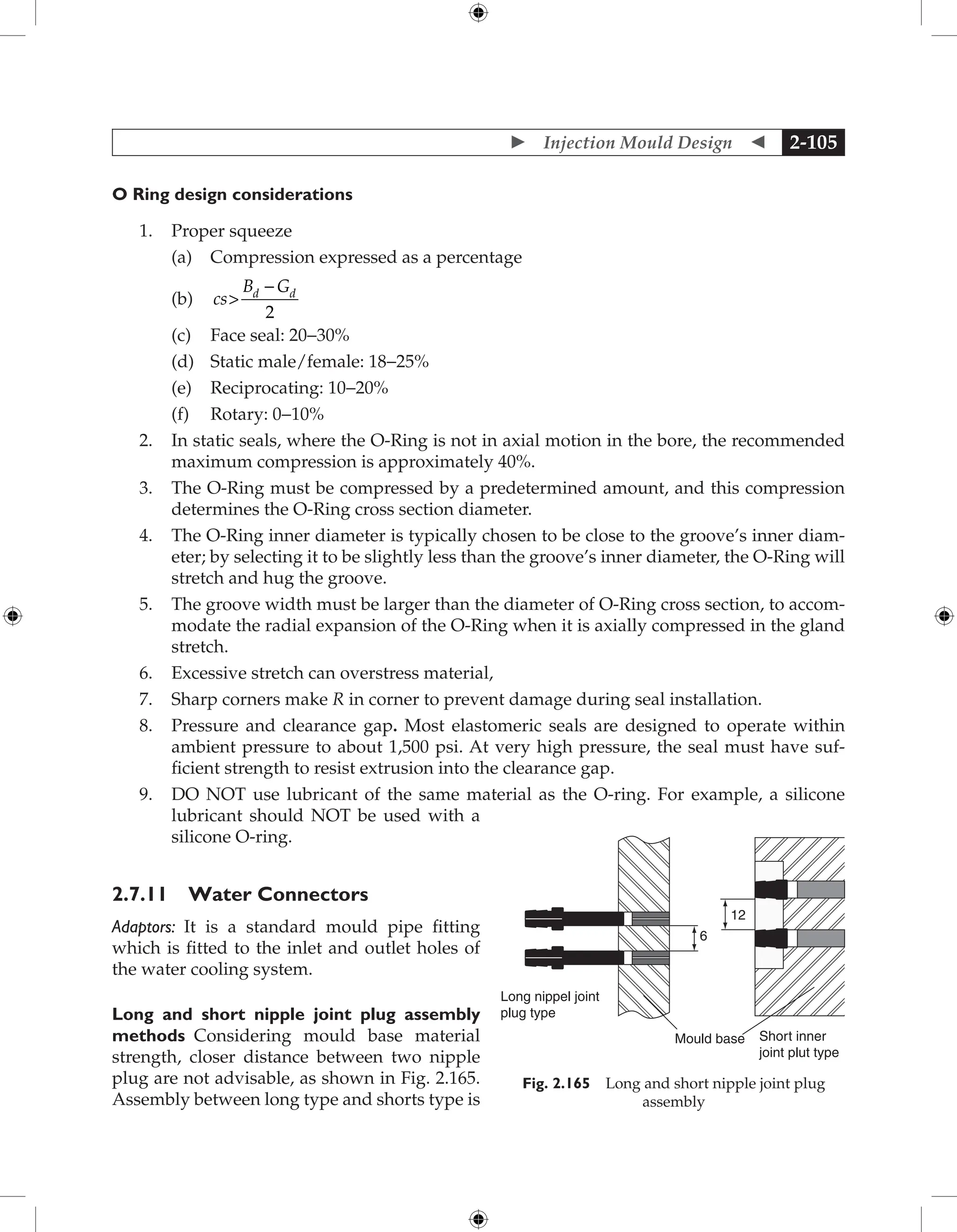
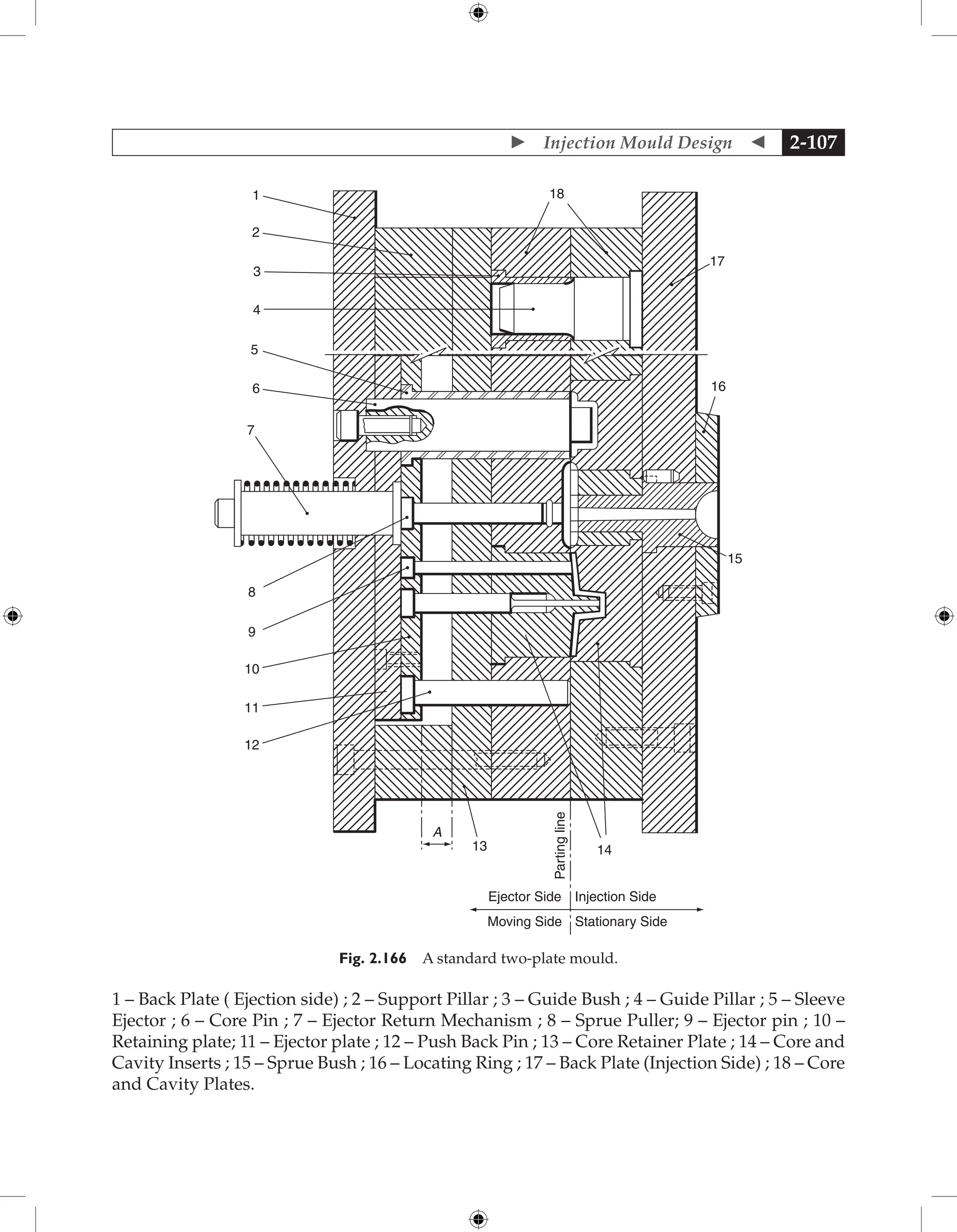
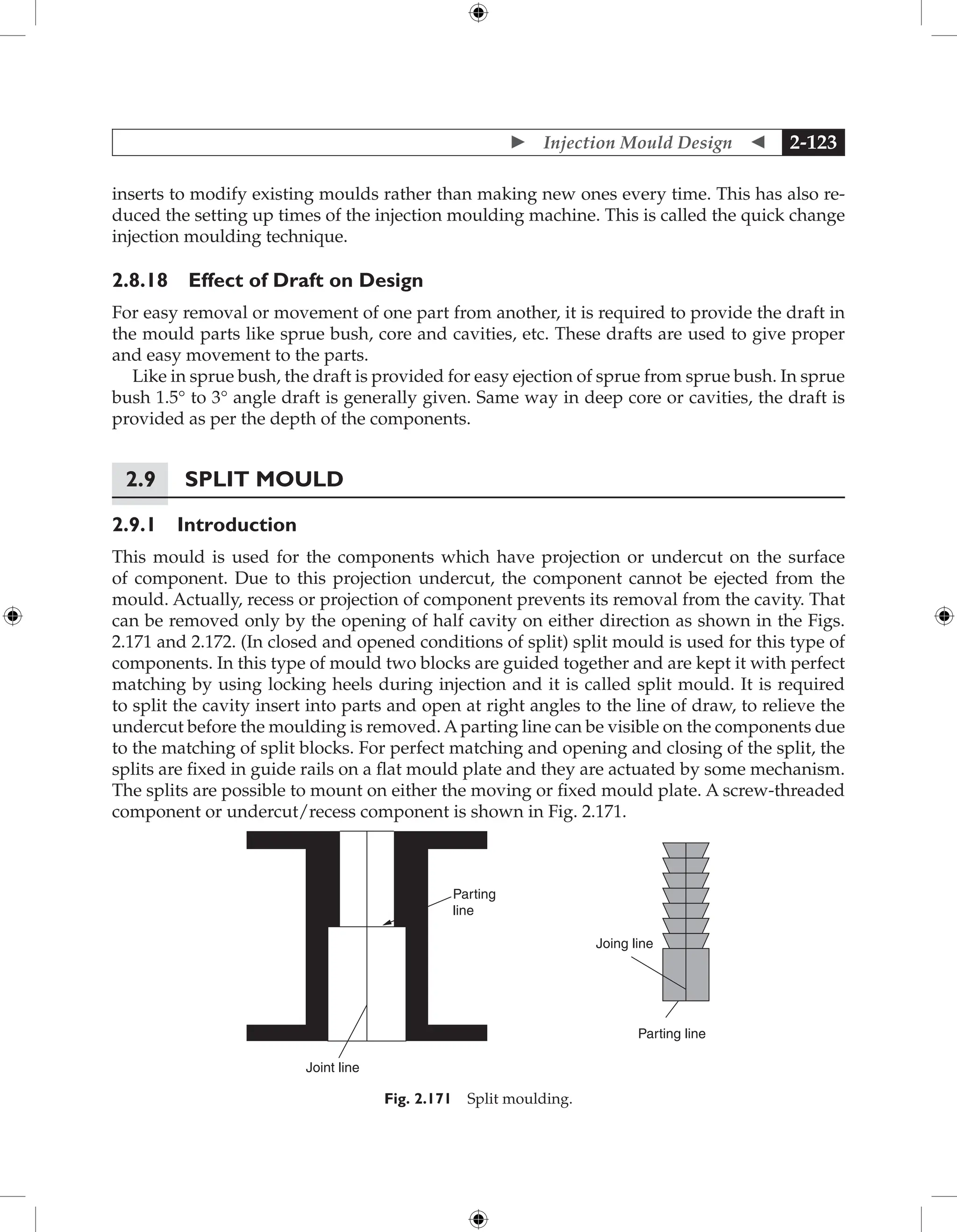
![ Injection Mould Design 2-101
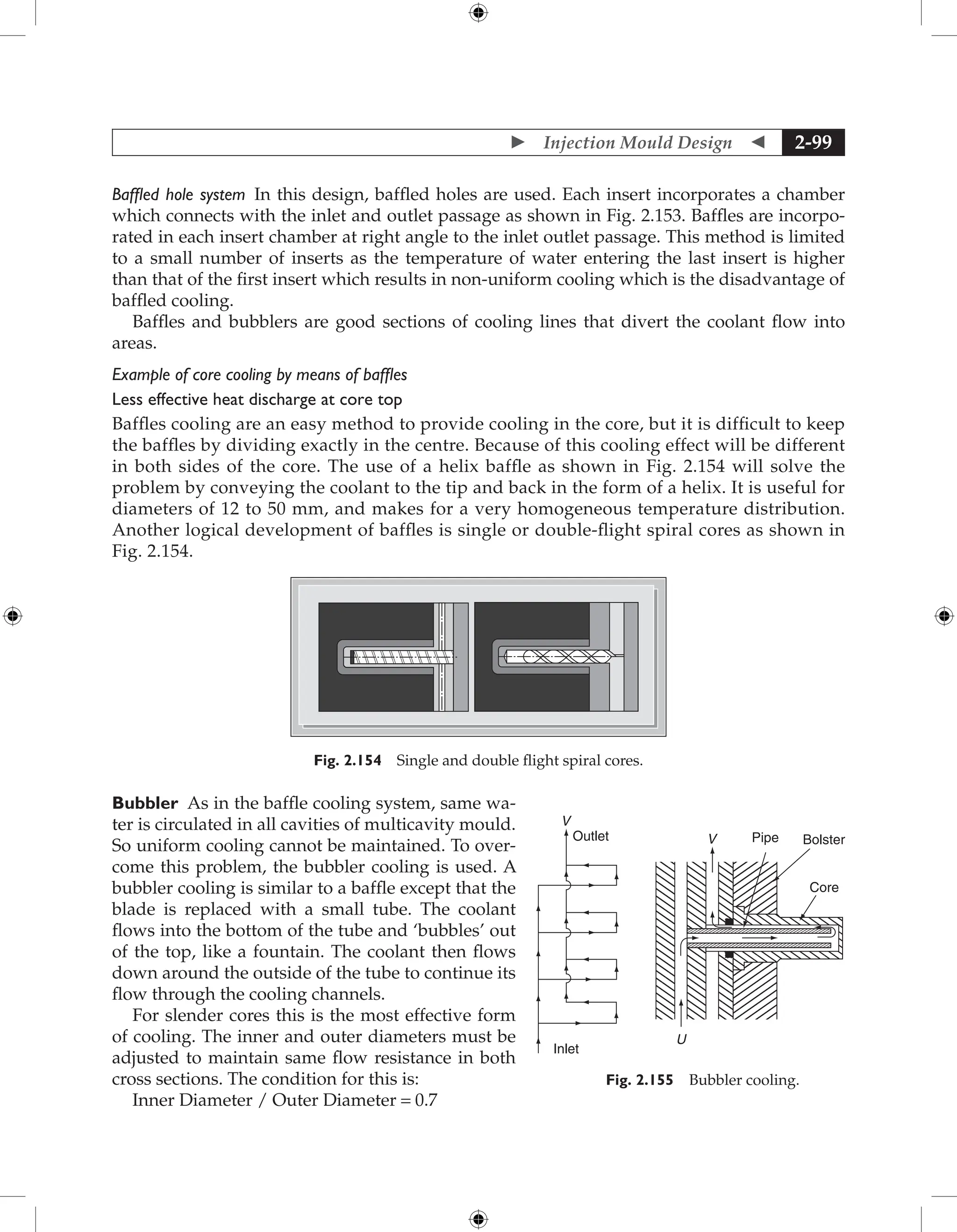
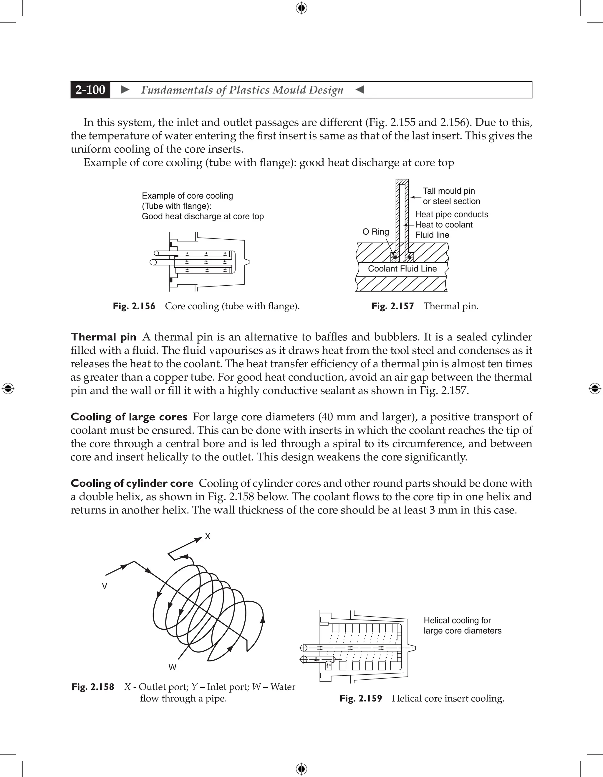
Helical channel design This design is adopted to en-
sure that the coolant follows a precise path and no
dead water is possible which results in rapid transfer
of heat from the moulding. Here the water follows
a helical path machined into a steel or brass block
which is fitted inside the chamber as shown in Fig.
2.158 and Fig. 2.159.
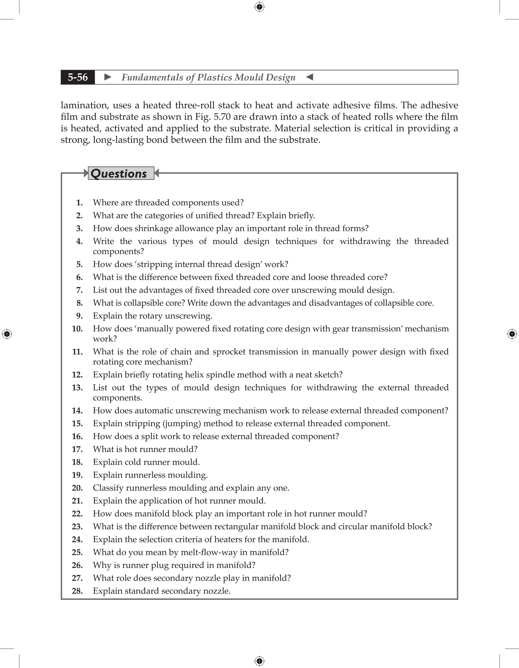
If the diameter or width is very small (less than
3 mm), only air-cooling is feasible. Air is blown at
the cores from the outside during opening or flows
through a central hole from inside as shown in Fig.
2.160. In this procedure the maintaining of exact
temperature is very difficult.
Better cooling of slender cores (those measuring less than 5 mm) is accomplished by using
inserts made of materials with high thermal conductivity, such as copper or beryllium-copper
materials. Such inserts are press-fitted into the core and extended with their base, which has
a cross section as large as is feasible, into a cooling channel as shown in Fig. 2.160.
2.7.5 Calculation of Rate of Heat to be Removed by Cooling Circuit
Q = M × [Cp {T 1 − T 2}+ L]
where Q = Heat to be transferred from mould per hour (cal/ hr)
Cp = Specific heat of material (cal/gm/ °C)
M = Mass of plastic material injected into the mould per hour (gm/hr)
L = Latent heat of fusion of plastic materials (cal/gm)
T1 = Injection temperature of material (°C ) ; T2 = Temperature of mould (°C)
2.7.6 Ejection Temperature
The operating temperature for a particular mould will depend on the following factors:
1. Type and grade of plastic material to be moulded
2. Length of flow within the impression
3. Wall section of the moulding
4. Length of the feed system
Maintaining the optimum temperature in a mould is very important as:
1. It improves the cycle time
2. It improves the quality of the product
3. It avoids distortion of the product
The holes or channels through which water/coolant passes are termed as flow ways and the
complete system of flow ways is called circuit.
Air
d
Fig. 2.160 Cooling of slender core insert.](https://image.slidesharecdn.com/fundamentalsofmoulddesign-231217032858-869d3d7e/75/Fundamentals-of-Mould-Design-lecture-pdf-296-2048.jpg)
![ Fundamentals of Plastics Mould Design
2-102
2.7.7 Weight of Water to be Circulated per Hour
The following formula gives weight of water to be circulated per hour to dissipate the heat;
Q = k m1 (Tout - Tin)
where Qw = Rate of heat extracted (kcal/hr)
k = Constant to allow for heat transfer efficiency
m1 = Weight of water passed (gm/hr)
Tout – T in = 5°C
For the component shown in the Fig. 2.2, the value of Q can be calculated as follows:
Q = 2316 × [0.5 × (250–60) + 20.1]
=
266571.6 cal/hr. = 266.57 kcal/hr (Assuming single impression and 1 min. cycle
time)
where Cp =
0.5 cal/° C/gm for PP; M = Shot wt. of the product × No. of shot/hr. = 38.6 gms.
(including 10% feed system) ; L = 20.1 cal/gm. For PP; T1 = Injection temp. of
PP; T2 = Mould temp. for PP
Weight of water to be circulated per hour is 266571.6 = 0.64 × m1 × 5 ; m1 = 83303.625 gm/hr =
83.3 kg/hr.
2.7.8 Cooling Time
Theoretically, cooling time is proportional to the square of the heaviest part wall thickness or
the power of 1.6 for the largest runner diameter. That is given in Table 2.15.
Table 2.15
Cooling time=
(Heaviest wallthickness)
Thermaldiffusivityof po
2
l
lymermelt
Cooling time=
(Largestrunnerdiameter)
Thermaldif
1.6
f
fusivityof polymermelt
wherethethermaldiffusivityof polymerme
eltisdefinedas
Thermaldiffusivity =
(Thermalconductivity)1.6
(
(Density)(Specificheat)
In other words, doubling the wall thickness quadruples the cooling time
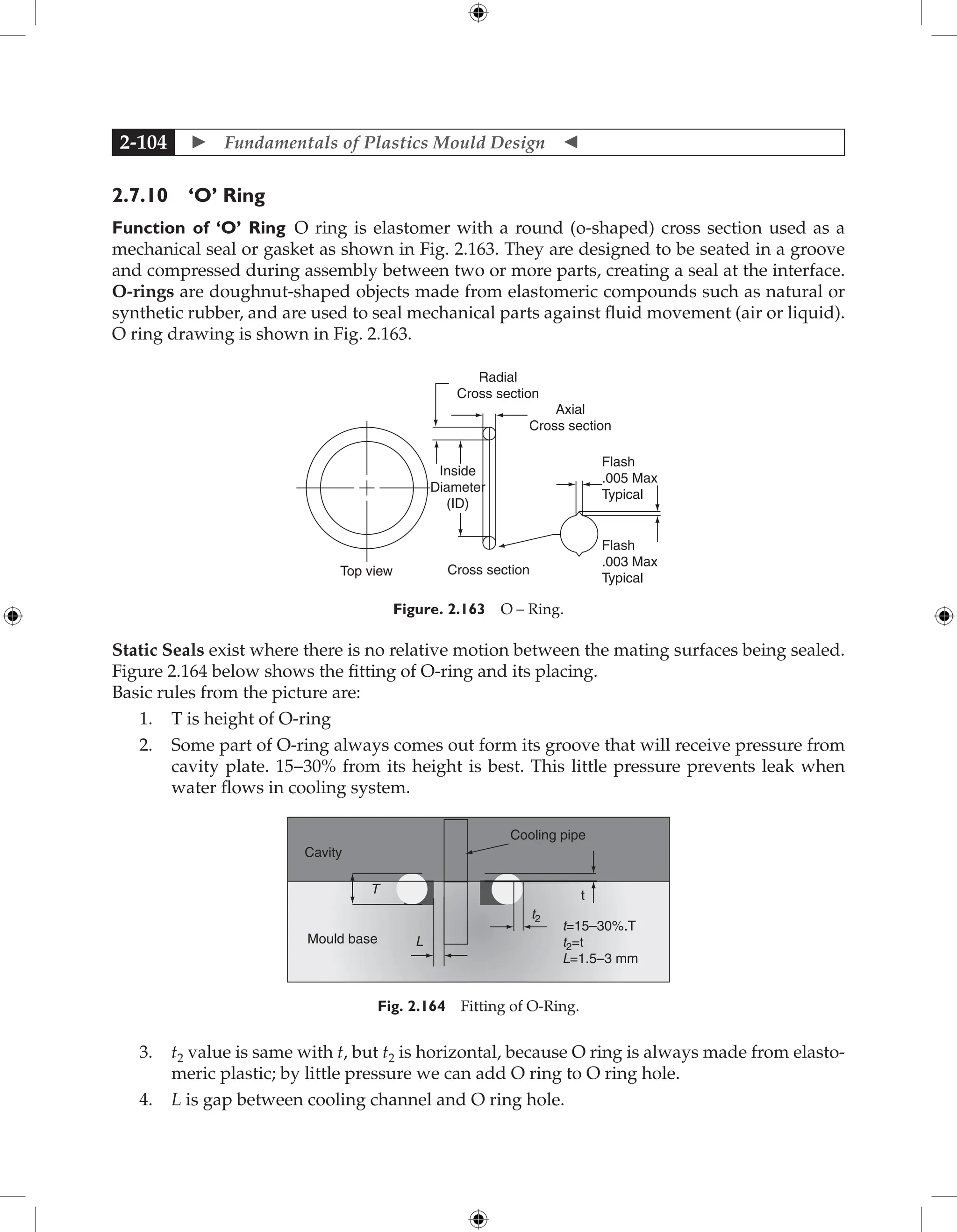
2.7.9 Cooling Channel Configuration
In general, the cooling system will be roughly drilled or milled. Rough inner surfaces enhance
turbulent flow of coolant, thus, providing better heat exchange. Turbulent flow achieves 3 to
5 times as much heat transfer as does non-turbulent flow. Cooling channels should be placed
close to the mould cavity surface with equal centre distances in between. The mechanical
strength of the mould steel should be considered when designing the cooling system.](https://image.slidesharecdn.com/fundamentalsofmoulddesign-231217032858-869d3d7e/75/Fundamentals-of-Mould-Design-lecture-pdf-297-2048.jpg)
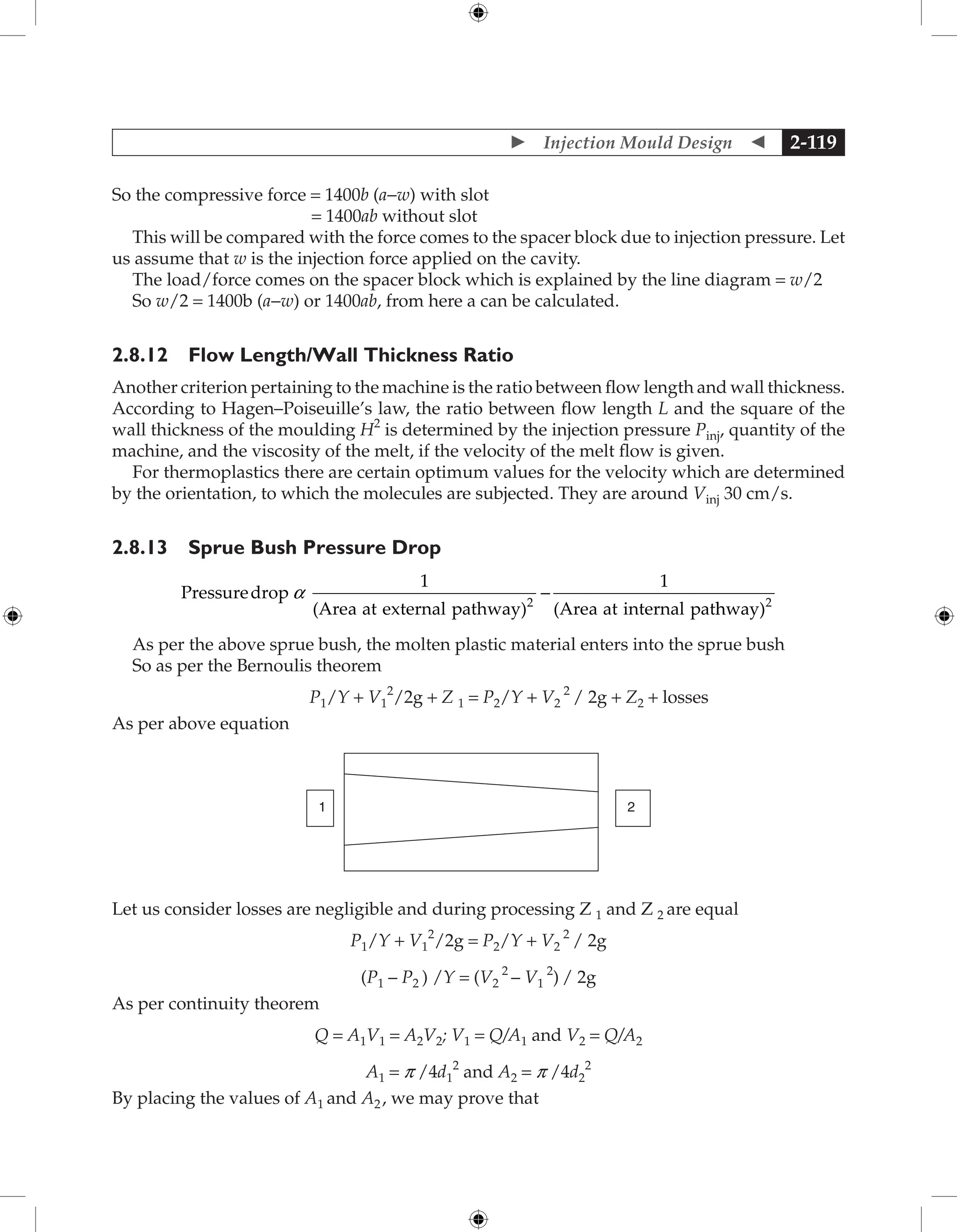
![ Fundamentals of Plastics Mould Design
2-120
Pressure drop
1
(Area at external pathway)
1
(Area at internal pat
2
a -
h
hway)2
2.8.14 Design of Step Ejector Pin
The critical force that will cause buckling of the ejector pin can be calculated as follows:
P = 2p 2
EM/l2
where P = Critical load (Kg), E = Modulus of elasticity (Kg/cm2)
M = Moment of inertia (cm4
), and l = Critical length (cm)
And stripping force which is required for the stripping of the moulding from the core
d1
d2
I
I1
I−I1
For the ejection;
Stripping force = P = 2 p 2
EM/l2
= 2p 2
E p d4
/64l2
= p3
Ed4
/32l2
Stripping force = P = (St × E × A × f p) / [d × (d/2t−d × Pp/4t)]
St = Coefficient of thermal expansion × temperature difference between softening point and
ejection temperature × d (cm)
E = Elastic modulus (kgf/cm2
)
A = Total area of contact between moulding and mould faces in line of draw (cm2
)
f p = Coefficient of friction between plastics and steel
d = Diameter of circle of circumference equal to length of perimeter of moulding
surrounding male core (cm)
t = Thickness of moulding
Pp = Poisson`s ratio of plastics
In the step pin, the diameter (d1)of the portion which is in contact with the plastic material is a
known quantity as per the wall thickness of moulding. We have to calculate the length (l1) of
this portion that can be done by placing d1 and find the length l1from the above equation.
After finding l1 from the above equation, the diameter of other portion d2 of the step pin can
be calculated by placing length of this portion l2 (total length – l1) in the above equation.
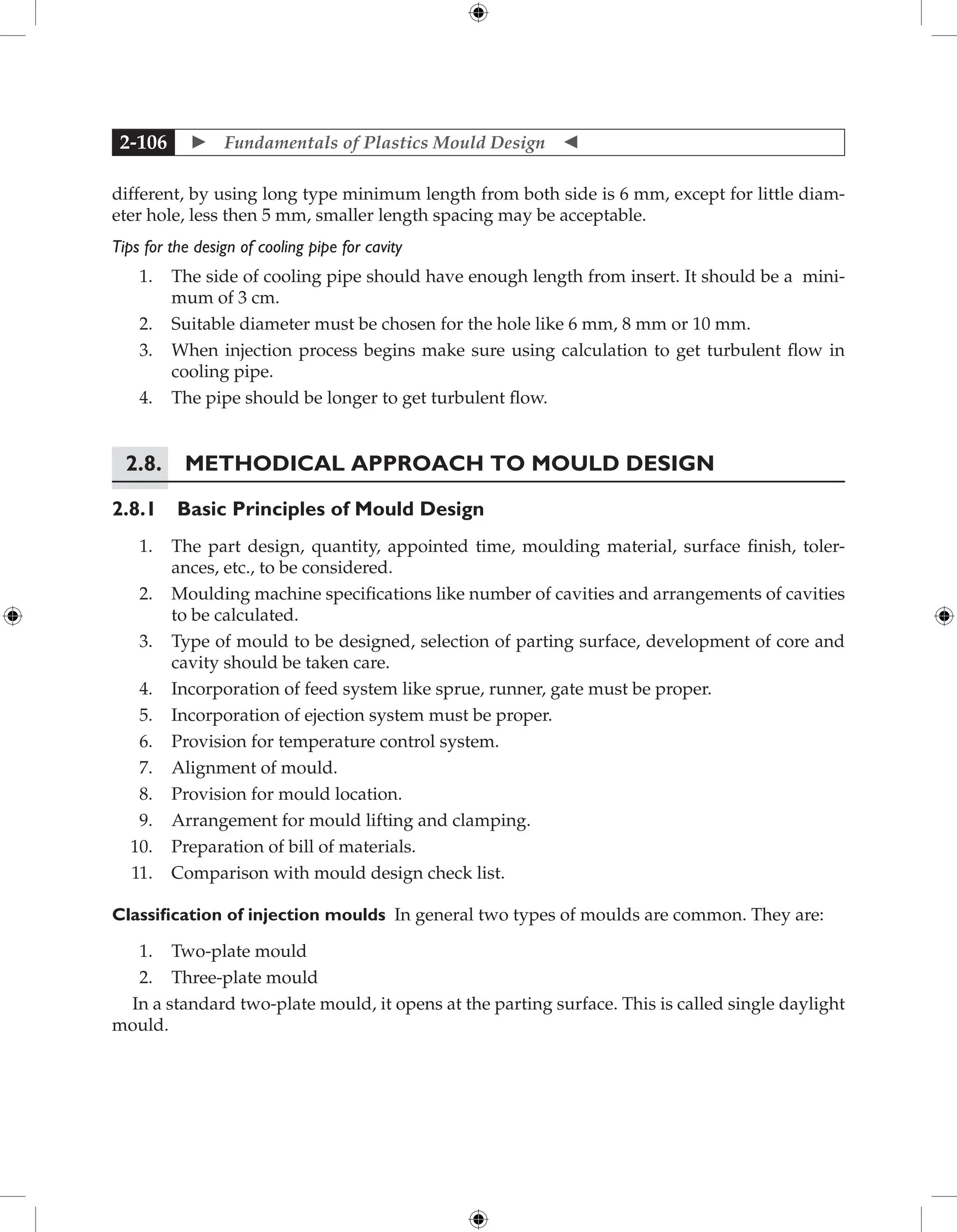
2.8.15 Heaters
The calculation is done to calculate number of heaters required for manifolds
Manifolds dimension is a × b × c](https://image.slidesharecdn.com/fundamentalsofmoulddesign-231217032858-869d3d7e/75/Fundamentals-of-Mould-Design-lecture-pdf-315-2048.jpg)
![ Fundamentals of Plastics Mould Design
2-122
S = Total manufacturing cost of the parts
By the above we may conclude that
No. of cycle required = n/x
Total time required = n T/x seconds = nT/60 x minutes
Total worker cost with overhead = n T w(1+r)/x
So S = {nT The temperature difference between mould plates and other plates from platen
side or platen w(1 + r)/60x} + Ax + B
This is the equation for the total cost of the parts. By differential calculation we try to get the
very economical number of cavities by assuming minimum manufacturing cost. For getting
this differentiates the equation with respect to x.
d/dx(S) = d/dx[{nTw(1+r)/60x} + Ax+B]
= d/dx[{nTw(1+r)/60x} + d/dx (Ax) + d/dx (B)]
= d/dx{nTw(1+r)/60x} + A
= d/dx{nTw(1+r)x-1
/60} + A
= -nTw(1+r)x–2
/60+ A = 0
A = nTw(1 + r)x–2
/60
x2
= nTw(1 + r)/60A
x = √nTw(1 + r)/60A by putting the values
x = √{1,00,000 × 60 × 25(1+0.15)/60 × 10,000}
x = 16.9 = 16 number of cavities
For the above data, 16 is the economical number of cavity. Now we have compared the
number with the technological number of cavity. Whichever is less, we have to design the
mould for that number.
2.8.17 Cost Reduction through Design Arrangement
1. Cost of the mould: The cost of a particular mould is expensive. To reduce the cost of the
mould, it would be better to go for multicavities injection mould by which the cost of one
product can be reduced. Take one example.
2. By the production of large quantities: The approximate cost of a mould that may make a
lunch box moulding may be Rs. 50,000 to Rs. 1,00,000. The capital cost is of course expensive
but consider that a single mould may produce ten lakhs of mouldings. Therefore, the unit cost
of each moulding can be very low because they are manufactured in such large quantities.
3. By the fabrication of multi-impression mould: DME can be further reduced by fabricat-
ing the mould in multicavities. In multicavities mould the cost of mould is increased by 1.4 to
1.5 times but the production cost is reduced due to number of cavities per cycle time.
4. By the fabrication of family type of mould: The mould cost is also reduced by fabricating
family type of mould.
5. By quick change insert system: By fabrication of one mould with different type of its
insert, cost of the mould can be reduced by quick- change tooling systems. These kits offer](https://image.slidesharecdn.com/fundamentalsofmoulddesign-231217032858-869d3d7e/75/Fundamentals-of-Mould-Design-lecture-pdf-317-2048.jpg)
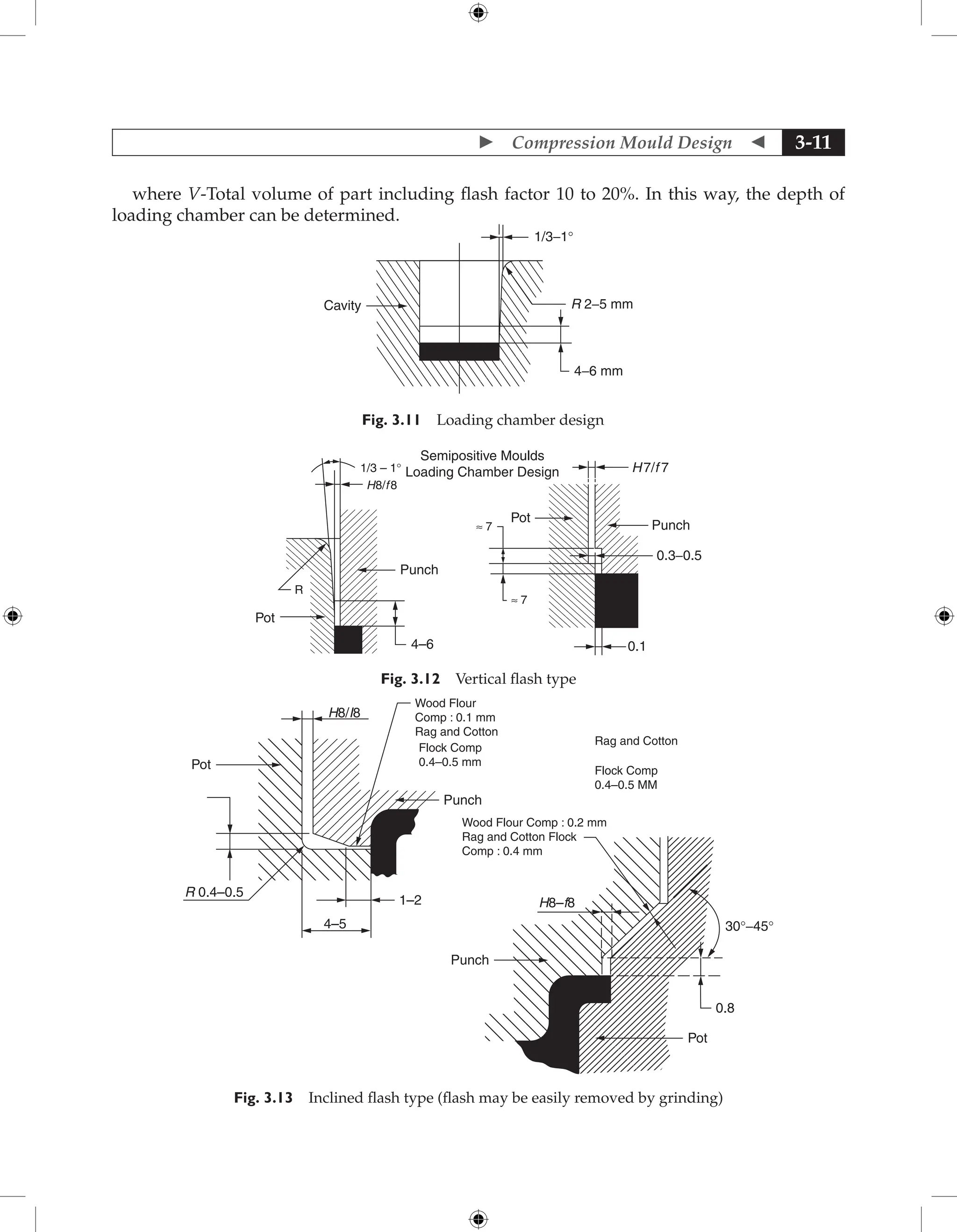
![ Compression Mould Design 3-15
3.9.2 Economical Determination
Let us assume that
1, 00,000 pcs = n = The total number of parts are required by the party.
x = Number of mould cavities to be fabricated
r = 15% of wages/hr = Overhead cost
w = ` 25 per hour = Wages of the workers
A = Production and maintenance cost of one cavity = ` 10,000/-
B = Production cost of mould casing
T = Cycle time = 60 seconds
S = Total manufacturing cost of the parts
By the above we may conclude that
No. of cycle required = n/x
Total time required= n T/x seconds = nT/60x minutes
Total worker cost with overhead = n T w(1 + r)/x
So,
S = {nT The temperature difference between mould plates and other plates from platen side
or platen
w(1 + r)/60x} + Ax + B
This equation derives the total cost of the part. By differential calculation, we try to get the
very economical number of cavities by assuming minimum manufacturing cost. For getting
this, differentiate the equation with respect to x.
d/dx(S) = d/dx[{nTw(1 + r)/60x} + Ax + B]
= d/dx[{nTw(1 + r)/60x} + d/dx (Ax) + d/dx (B)]
= d/dx{nTw(1 + r)/60x} + A
= d/dx{nTw(1 + r)x-1
/60} + A
= -nTw(1 + r)x-2
/60 + A = 0
A = nTw(1 + r)x-2
/60
x2
= nTw(1 + r)/60A
x = √nTw(1 + r)/60A by putting the values
x = √{1,00,000 × 60 × 25(1 + 0.15)/60 × 10,000}
x = 16.9 =16 number of cavities
For the above data, 16 is the economical number of cavity. Now we have compared the number
with the technological number of cavity. Whichever is less, we have to design the mould for
that number.](https://image.slidesharecdn.com/fundamentalsofmoulddesign-231217032858-869d3d7e/75/Fundamentals-of-Mould-Design-lecture-pdf-348-2048.jpg)


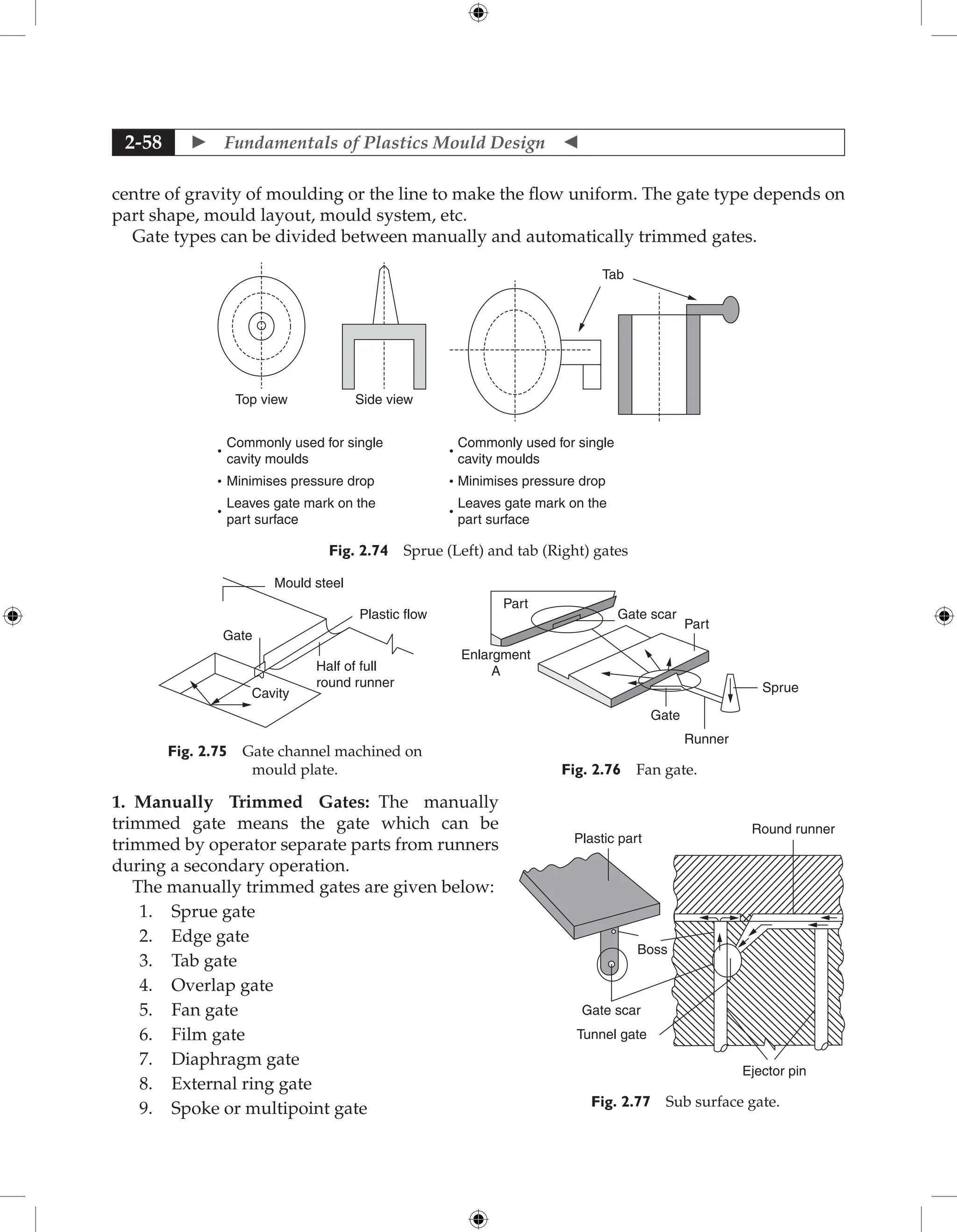
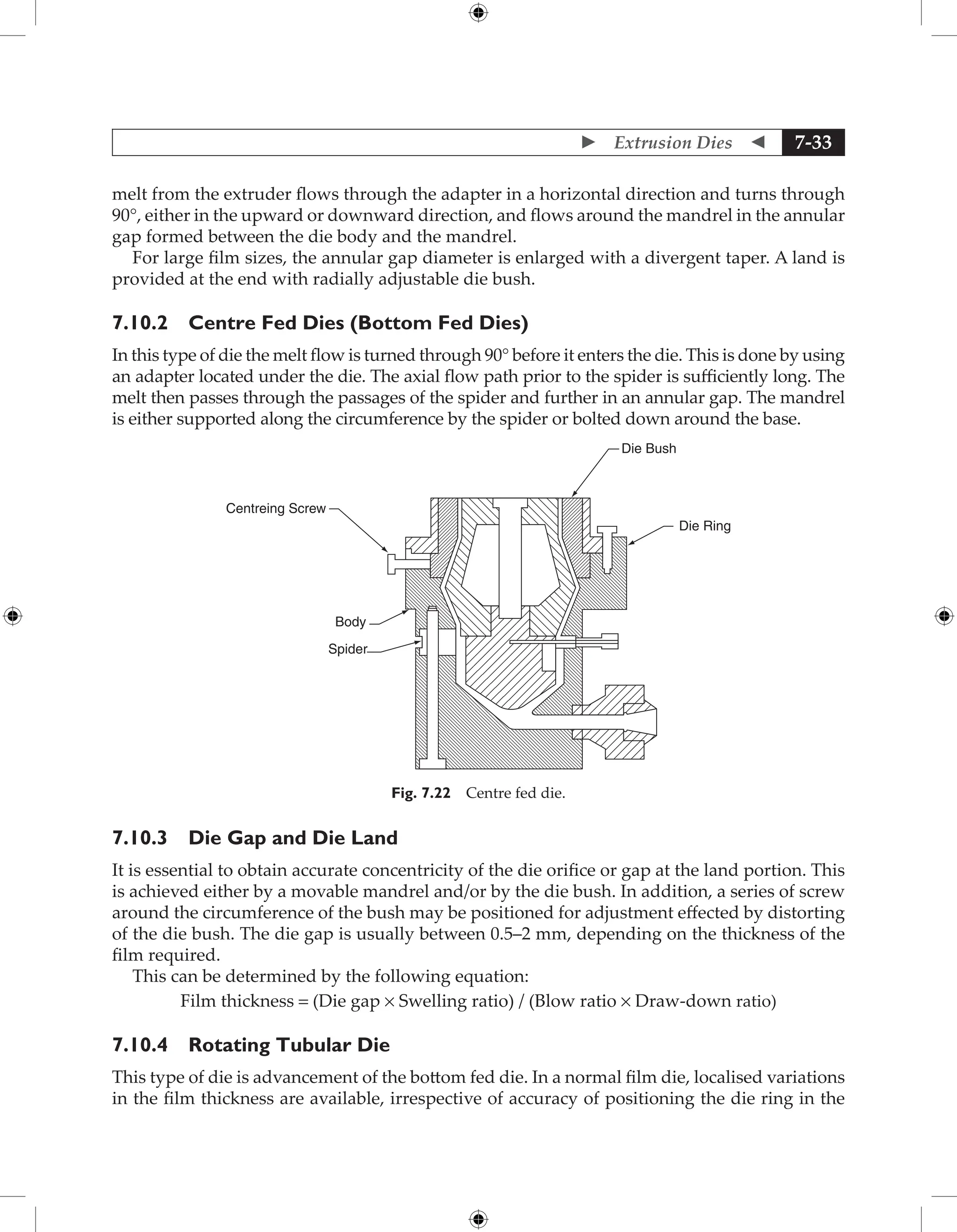
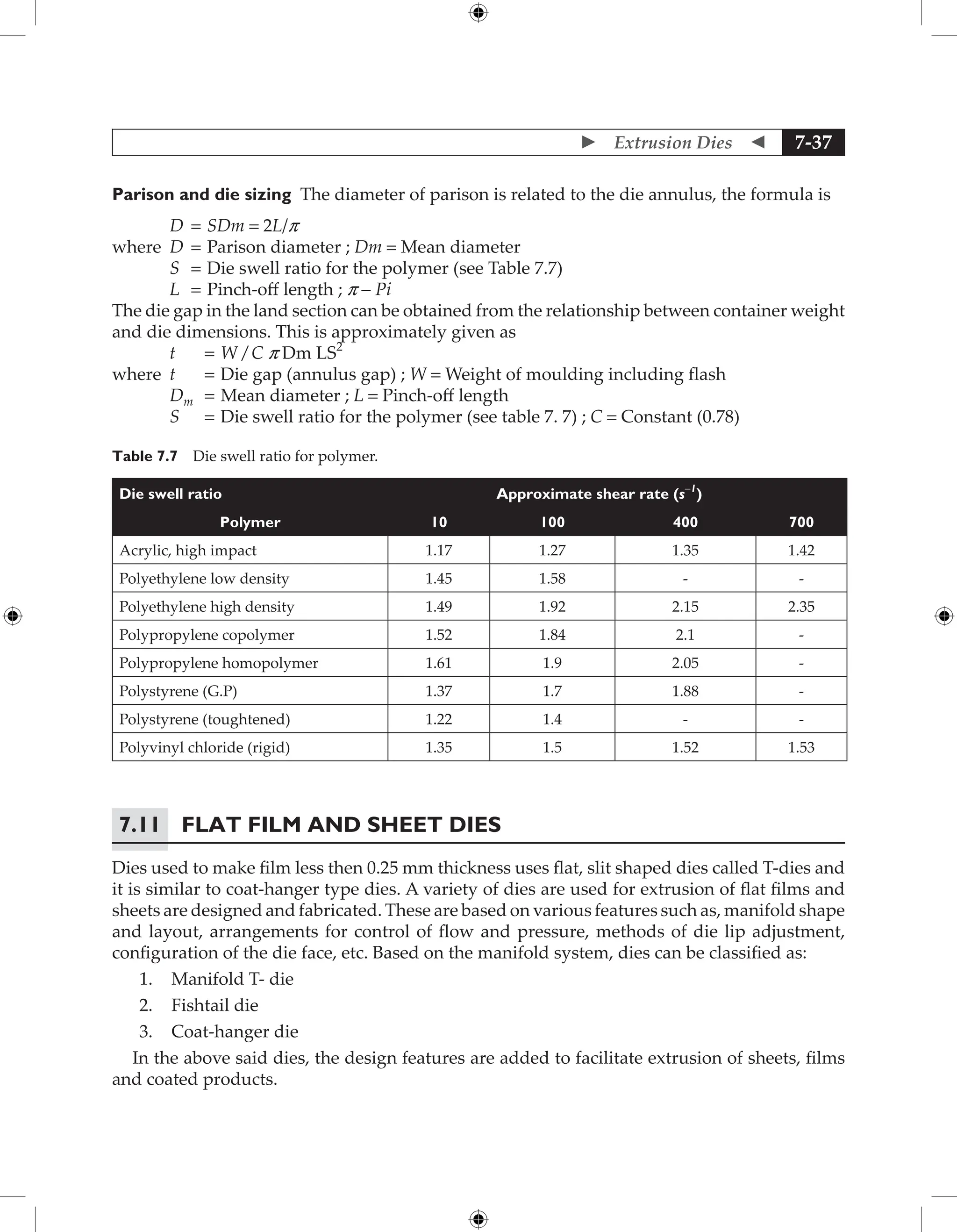
![ Fundamentals of Plastics Mould Design
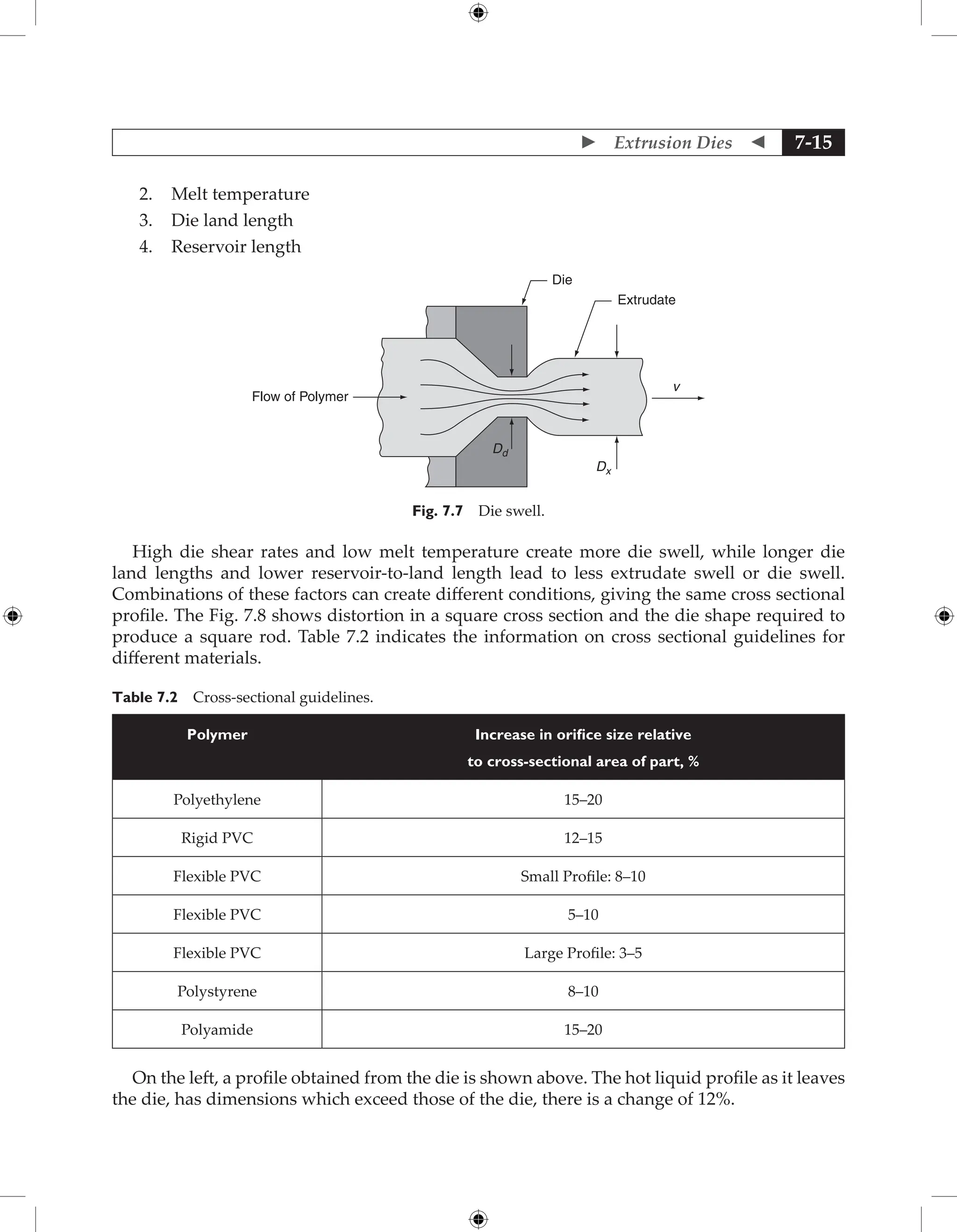
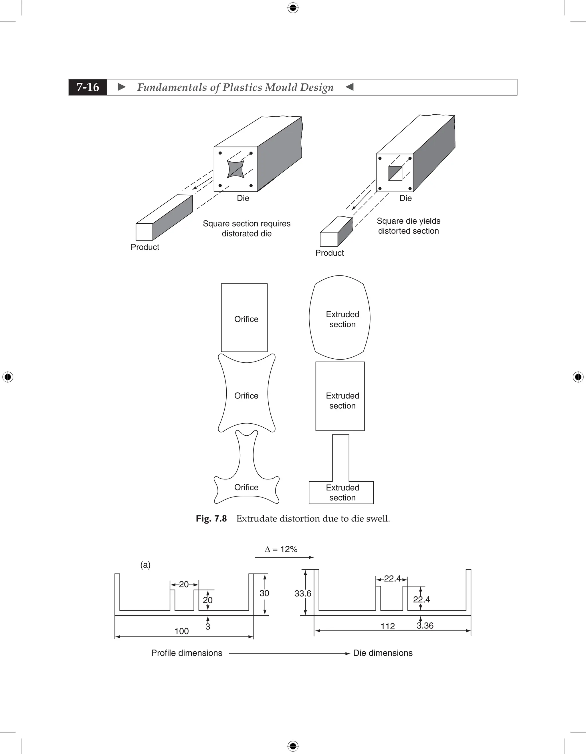
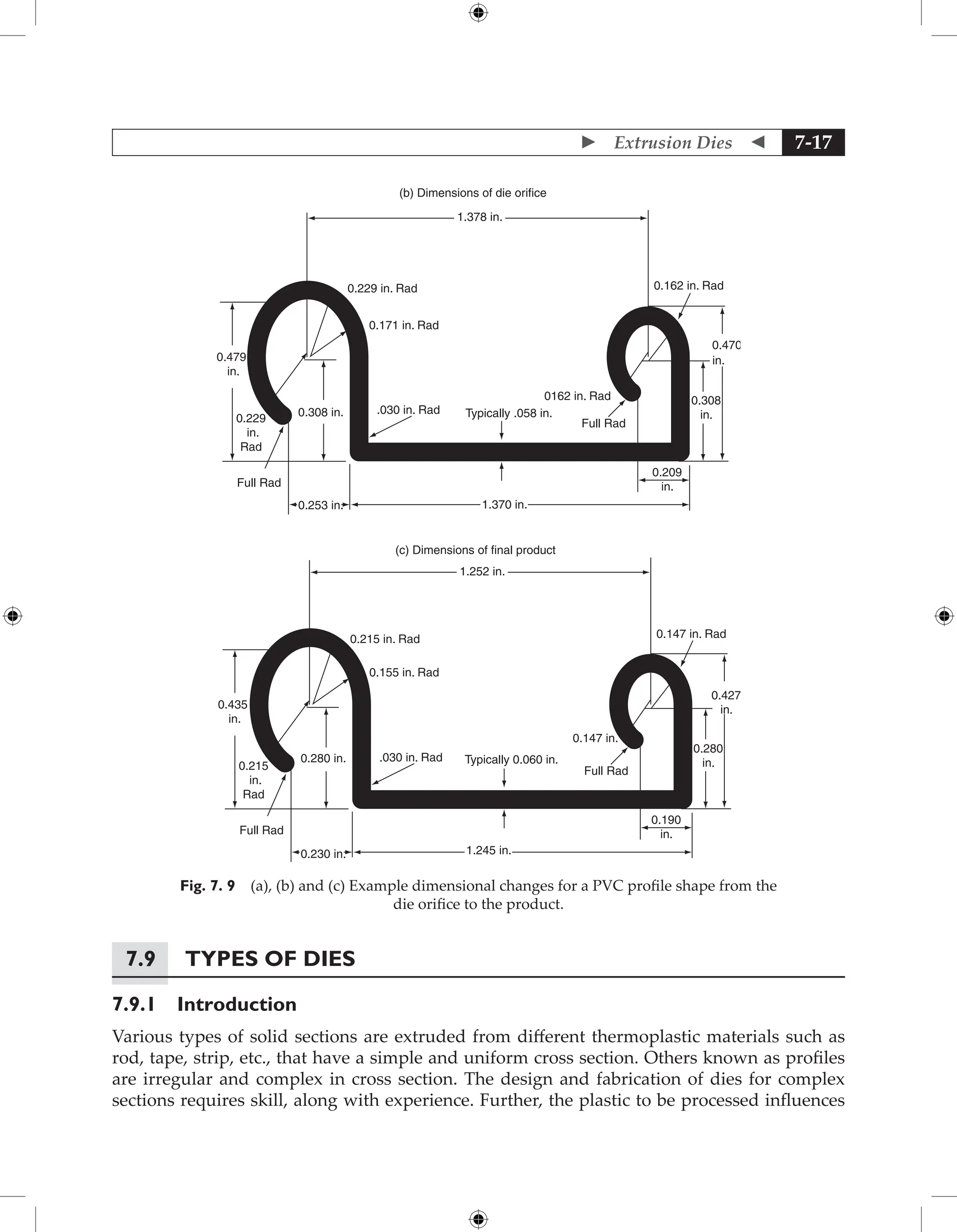
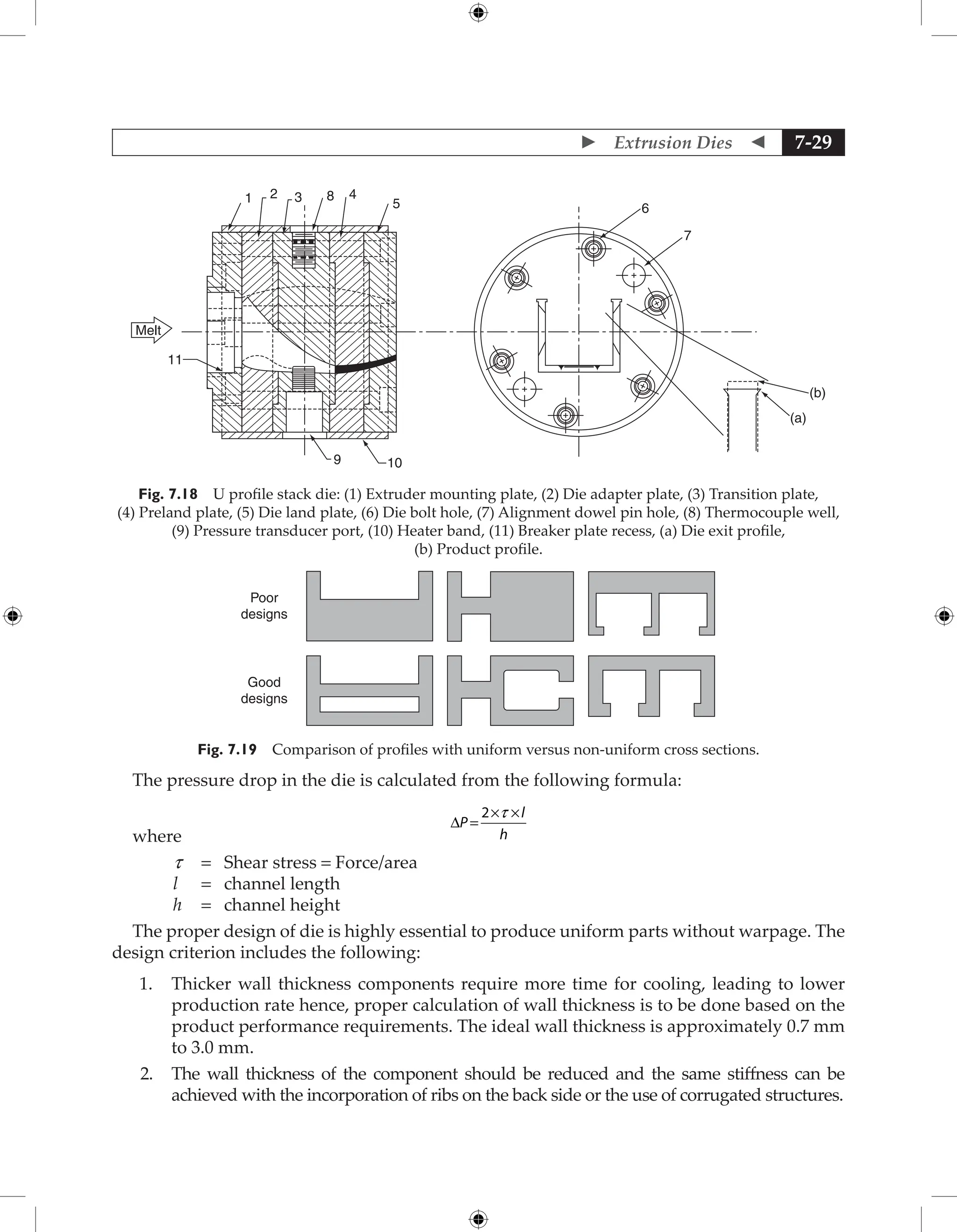
7-18
die dimensions and these dies are designed especially
for extrusion of specific plastics and their compounds.
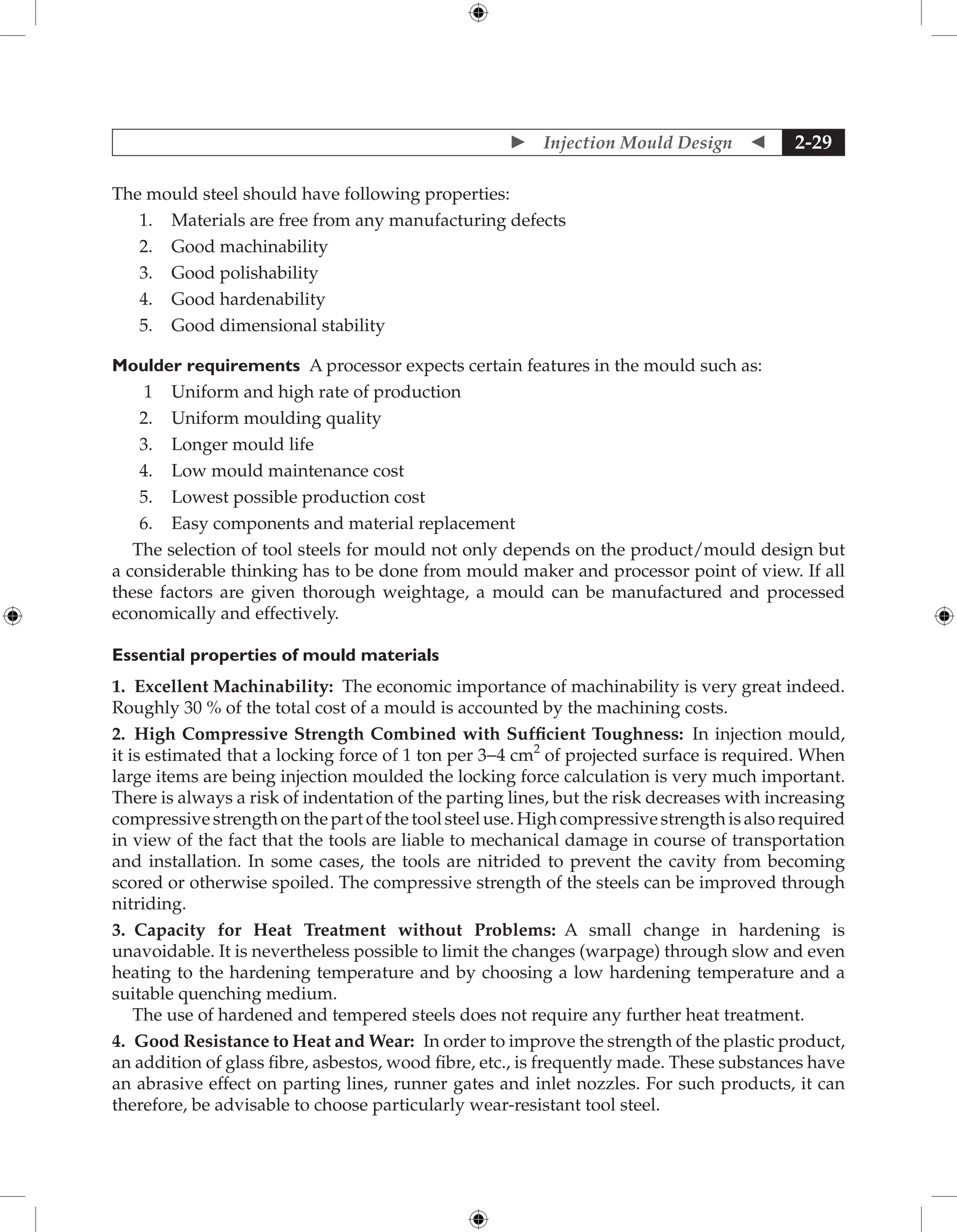
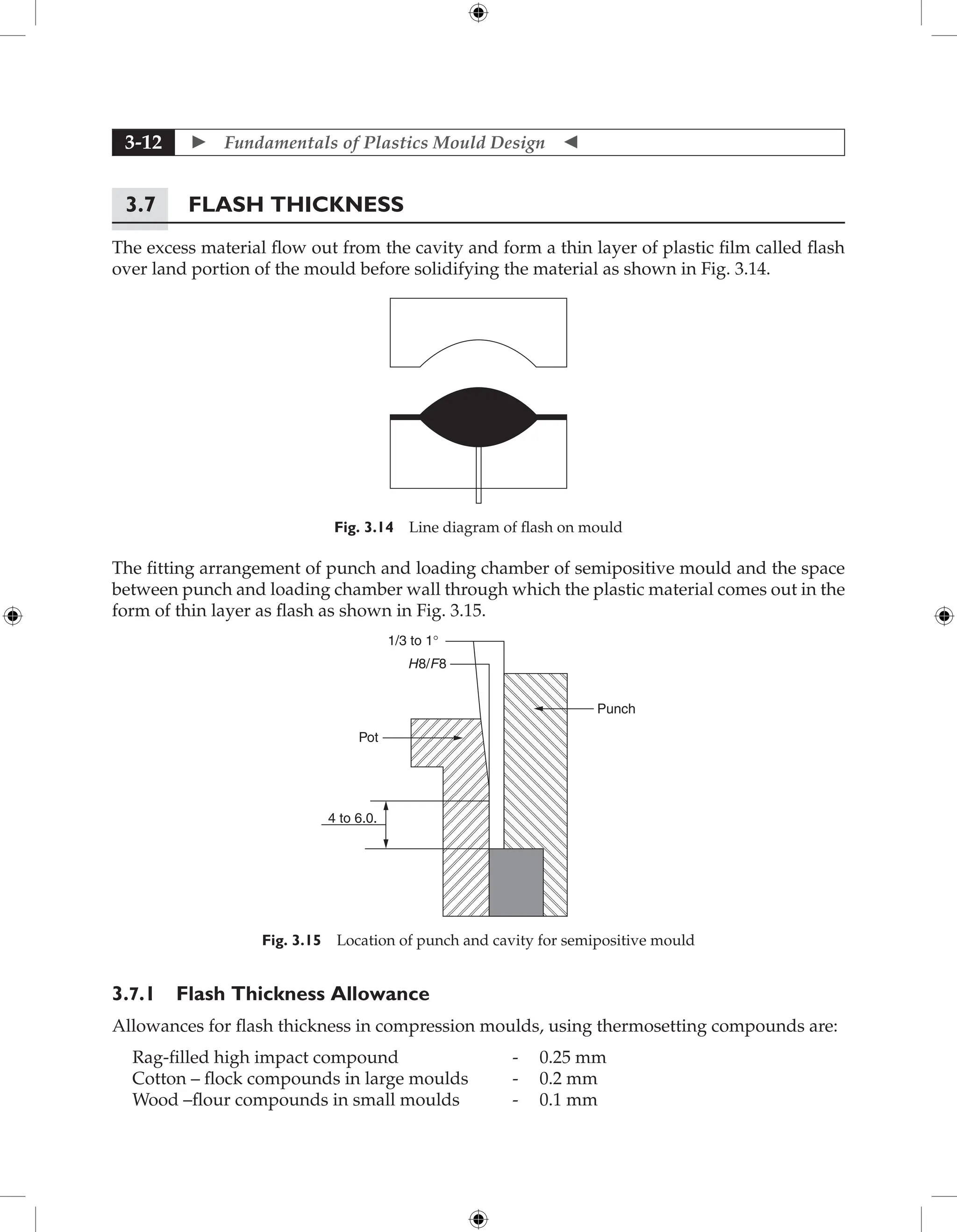
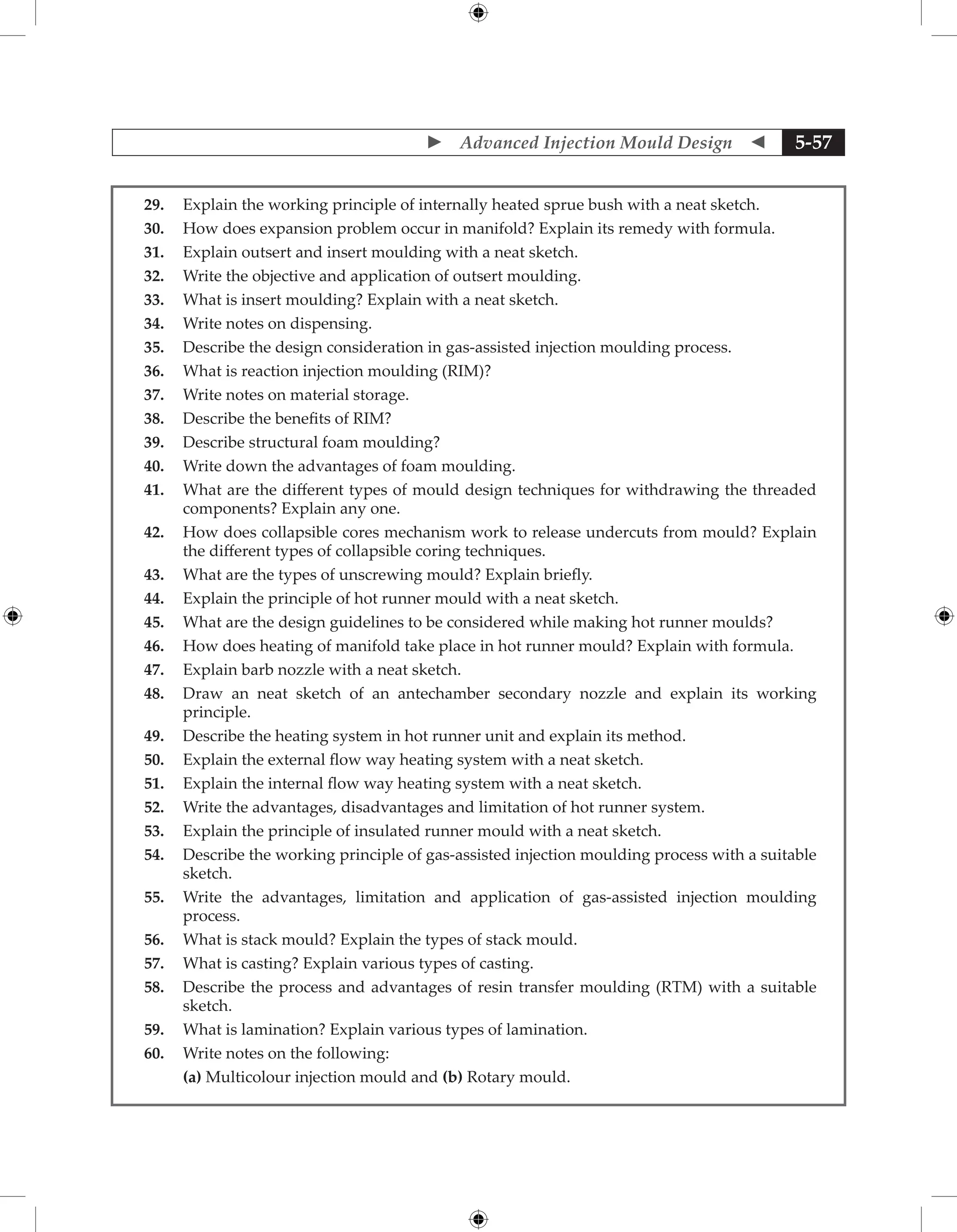
7.9.2 Rod Die
The rod die has a simpler geometry and it consists of
an approach section with a taper of 60° to 90° included
angle. The length of the land depends on the material
extruded, rod diameter, extrusion rate, etc., and special
care to be taken while designing dies for crystalline
polymers such as nylon and polyacetal. In these
materials, rapid volume change takes place during post
extrusion cooling and solidifying, which will create
voids in the central portion of rods. With amorphous
polymers such as polycarbonate and PVC, the change
in specific volume is more gradual and limited.
The method of extruding rods in nylon is free extrusion into a water quench bath which
requires a circular die land that has a diameter 1.7 to 2.0 times the diameter of the desired rod.
A closely balanced cooling system is necessary to obtain a round, void-free rod. Shrinkage
voids are usually eliminated by shortening the length of quench bath, by air quenching
or by a hot oil bath. This method is suitable for making rods up to 12.5 mm diameter. For
larger diameter rods or where precise control of diameter is desired, a forming box method is
used. The molten mass is extruded under pressure through a short die land, then through a
converging section and finally through a cylindrical water-cooled tube. The rod is thus shaped
by the pressure from the extruder, which supplies the melt continuously to the central cone
and eliminates voids due to shrinkage.
Example for design of die for a rod
Data given or assumed
Extruder size [Es] - 45 mm
Extruder output (Qm) - 30 kg/hr
Rod diameter[Pd] - 15 mm
Material- L. D. polyethylene
Properties
Solid density (rs) - 0.923 gm/cm3
Melt density (rm) - 0.76 gm/cm3
at 170°C
Power law constants (at 170°C)
(n) - 1/3
(k) - 3250 kg (f) sec-1
/ m2
Extensional viscosity (l) - 0.822 * 104
kg (f) sec/ m2
Critical extensional strain rate (ee) - 18 sec-1
La L
t
E
s
D
b
Fig. 7.10 Rod die.](https://image.slidesharecdn.com/fundamentalsofmoulddesign-231217032858-869d3d7e/75/Fundamentals-of-Mould-Design-lecture-pdf-522-2048.jpg)
![ Extrusion Dies 7-19
Permissible tensile strength of die material (f) - 1400 kg/cm2
Design Calculation
1. Volumetric output of extruder
Qv = Qm × 1000 / rm
= (30*1000)/ 0.76 = 39500 cm3
/hr
2. Velocity of melt
V = Qv/A = (Qv/60) * (4 / p Es2
)
= (39500/60) * (4/p 0.452
) = 372 cm/min = 3.72 m/min.
Land section
Assuming land length to be twice the product wall and land wall to be 10% larger than product
to accommodate draw down.
Land section (L) = 30 mm
Land diameter (D) = 16.5 mm
Designing for length of approach section
PL = [((3n + 1)/n) (Qv / pR3
)] n (2kL / R)
where Qv = Volumetric flow rate
R = Radius of land
L = Length of land
PL = Pressure drop in land
K and n are power law constants
PL =
[(((3 × 1/3) + 1)/ (1/3)) × (39500/ (60 × 60)) × (1 / (p × (1.65/2)3
))] 1/3
× [((2 × 3250)/
104
) × (3 /(1.65/2))]
= 6.25 kg / cm2
Shear stress
tw = (RP)/2L = (1.65 × 6.25) / (2 × 2 × 3.0)
= 0.859 kg / cm2
Shear rate
gw = ((3n + 1) / n) ( Qv / pR3
)
= 6 × (39500/(60 × 60)) ( 1/( p (1.65/2)3
)
= 37.74 sec-1
Approach section
To calculate approach angle a
tan a = 2 ec / g
where ec = Critical extensional strain rate
g = Shear rate
tan a = 2 × 18/37.74 = 0.954
a = 43o
40’](https://image.slidesharecdn.com/fundamentalsofmoulddesign-231217032858-869d3d7e/75/Fundamentals-of-Mould-Design-lecture-pdf-523-2048.jpg)
![ Fundamentals of Plastics Mould Design
7-20
Extruder size = 45 mm
Tan a (45 – 16.5) / ( 2 * La )
where La = Length of approach section
La = 15.1 mm.
Calculation for Minimum Thickness of Die Wall
Pressure drop in the approach section
Ps = (2t/3n tan a ) [ 1 – (R0/Ri )3n
]
= (2 × 0.859)/(3 × 1/3 × 0.954) [ 1 – (16.5/45)3 × 1/3
]
= 1.14 kg/cm2
Pe = ((2lec)/3) [ 1 – (R0/Ri )3
]
= ((2 × 0.822 × 104 ×
18 )/3) [ 1 – (16.5/45)3
]
= 9.38 kg/cm2
So, pressure drop in approach section = 1.14 + 9.38 = 10.52 kg / cm2
Assuming no pressure drop in the breaker plate, screen pack and the adapter.
Total pressure drop in die (Pt) = Pressure drop in land + Pressure drop in approach
Pt = 6.25 + 10.52 = 16.77 kg / cm2
Minimum die wall thickness (t)
From Eq. t = (D/2) [ ( ( f + Pt ) / ( f – Pt ))1/2
− 1 ]
where, D = Land diameter
f = Permissible tensile strength of die material
Pt = Total pressure drop in die
So, t = (16.5/2) [((1400 + 16.77) / (1400−16.78))1/2
− 1 ]
= 8.25 * 0.01 = 0.0825 mm.
Actual wall thickness is to be decided depending upon assembly situation.
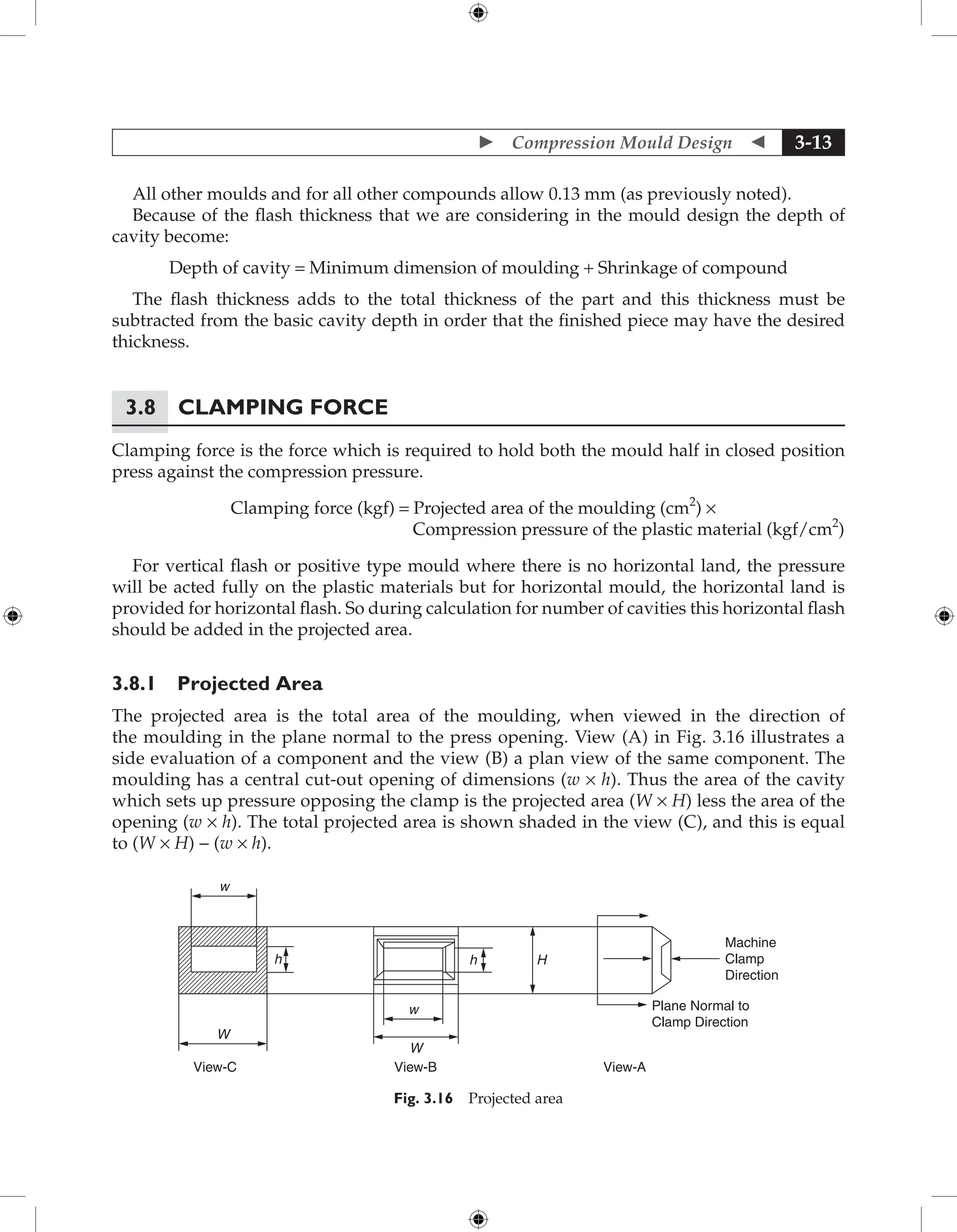
7.9.3 Pipe Die
Pipe is basically a hollow and symmetric round cross sections and a pipe extrusion line is
very similar to a profile line with a vacuum sizing cooling unit, puller, and saw or on cutter.
Products can be rigid or flexible and vary from something very small, such as a catheter tube
used in medical applications, to large-diameter pipe used to transport water or other fluid.
Pipe or tubing can be wound up as a continuous product or cut to length. Pipe and tubing can
be extruded for added value and to meet specific end-use requirements.
There are different types of die used for manufacturing of pipes. Various types of dies are
in line or straight through or offset type.
Function of die
The extrusion head or die is determined by the diameter and wall thickness required in the
final product. The extrudate enters directly from the extruder through the breaker plate into
the die. Large dies require a die stand to support the die weight and prevent distorting the
extruder barrel. An adapter is present between the extruder and the pipe or tubing die, versus
the direct connection the entrance cone distributes the melt uniformly around the mandrel.
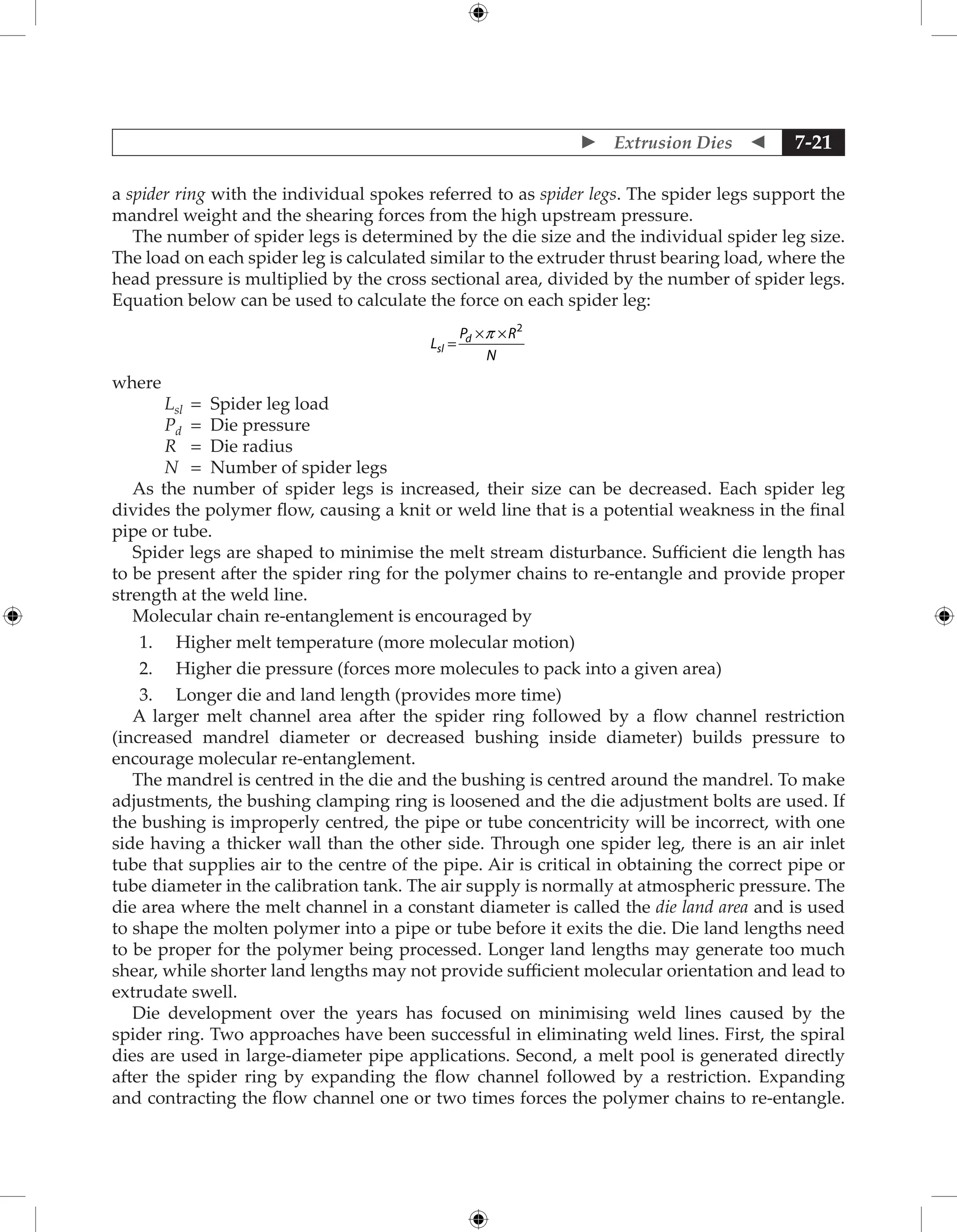
The mandrel or centre section is held in place by spokes radiating out from the mandrel called](https://image.slidesharecdn.com/fundamentalsofmoulddesign-231217032858-869d3d7e/75/Fundamentals-of-Mould-Design-lecture-pdf-524-2048.jpg)
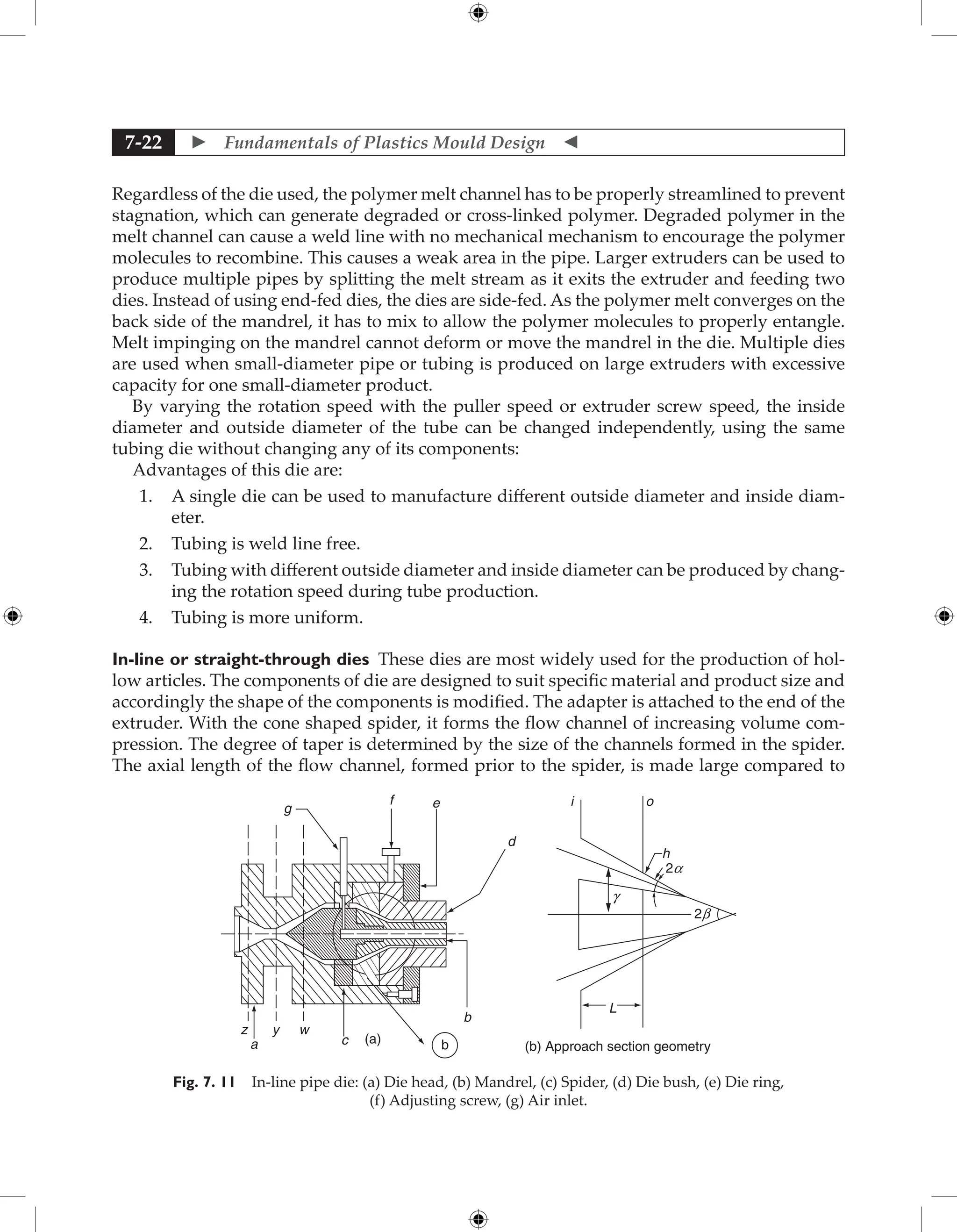
![ Extrusion Dies 7-23
the dimensions of the flow channel in the spider. This helps to reduce the obstruction to melt
flow in the spider channels. High melt temperature and frictional drag in the spider passage
should be avoided. The ratio between the land length and the annular gap which forms the
wall thickness varies between 10 to 30. The annulus is usually designed to oversize to allow
for some draw down and an excess diameter of 10 to 30 per cent is usual. The mean diameter
of the annular gap should be 5 to 25 per cent larger in the case of pipes. The lower values refer
to rigid PVC and larger values to polyolefin’s.
Cross section of flow should gradually decrease from section ‘z’ to ‘y’ to ‘w’ (see Fig. 7.11).
Example for design of in-line pipe die
Data given or assumed -
Extruder size [Es] - 65 mm
Extruder output (Qm) - 60 kg/hr
Outside diameter of pipe - 90 mm
Thickness of pipe - 4.5 mm
Material and its property - H.D. Polyethylene
Density of solid (rs) - 0.955 g /cm3
Density of melt (rm) - 0.81 g /cm3
at 170°C
Power-law constants
K - 631 kg(f) sec- 0.56
/m2
n - 0.56
Design calculation
1. Volumetric output of extruder
Qv = Qm × 1000 / rm
= (60 × 1000) / 0.81 = 74074 cm3
/hr
2. Velocity of melt V = Qv/A = ( Qv/60 ) × (4/p Es2
)
= (74074/60) × (4/p 0.652
)
= 372 cm/min = 3.72 m/min.
Land section
Assuming land length to be 15 times the product wall thickness and land wall to be 2% larger
than product to accommodate draw down.
Outside diameter of annulus - 90 * 1.02 = 91.8 mm
Inside diameter of annulus (mandrel diameter) - 91.8 - (4.5 * 2) = 82.8 mm
Land length - 15 * 4.5 = 67.5 mm
Shear rate in land
Shear rate (g ) = (6 Qv) / [ p (R0 + Ri)(R0 - Ri)2
]
= (6 * 74074) / [ p (4.59 + 4.14)( 4.59 – 4.14)2
× 3600 ]
= 22.24 sec-1](https://image.slidesharecdn.com/fundamentalsofmoulddesign-231217032858-869d3d7e/75/Fundamentals-of-Mould-Design-lecture-pdf-527-2048.jpg)
![ Fundamentals of Plastics Mould Design
7-24
where Qv = Volumetric output of extruder
Ri = Inlet radius of taper
R0 = Outlet radius of taper
Pressure drop in land can be obtained from (assuming thickness very less compared to
radius)
Qv = (n / (2n + 1)) * (p R0
3
) [ (R0 P) / (2KL) ] 1/n
( (b - 1) / b )((2n + 1) / n)
( ( 1 + b ) / 2b )
where P = Pressure Drop in Land
b = R0 / RI = 4.59 / 4.14 = 1.11
k, n = Flow behaviour index
Ri = Inlet radius
R0 = Outlet radius
L = Land length
Q =
{(0.56/2.12) × p × (4.59)3
) [ (4.59DP)/(2(631/104
))]1/0.56
((0.11–1.11)(2.12/0.56)
(2.11/2.22)}
= 0.012 × (5.388 P)1.785
P1.785
= 22.24 / ( 0.012 × 20.21) = 91.71
P = 12.57 kg / cm2
Approach section
Assuming angle of approach (convergence) b = 20°
2b = 40°
and assuming 2 a = 10°
Assuming the length of approach section = 100 mm
Pressure drop in approach section = Due to simple shear flow (Ps) + Due to Extensional
Flow (Pe)
Ps = ( Kg n
/ Ho ) (1 / (U - V)) loge [ (1 + UL) / (1 + VL) ]
Pe = [ 1 − (RoHo
2
/ RiHi
2
) ] l / 2
where K, n = Power law constant; g = Shear rate;
l = Viscosity under simple tension
Ro = Mean radius in outlet of approach section
Ri = Mean radius in inlet of approach section
Hi = Half Gap in inlet of approach section
Ho = Half Gap in outlet of approach section
L = Length of approach section
U = ( (tan a sec b ) / Ho )
V = n [ (tanb / Ro ) + 2U ]
U = ( (tan a sec b ) / h0 ) = (0.0875 × 1 ) / (( 0.45/2) × 0.94 ) = 0.41 cm
V = n [ (tanb / R0 ) + 2U]
= 0.56 [ (0.364 / 4.59 ) + (2 × 0.41) ]
= 0.56 × 0.899
= 0.5 cm](https://image.slidesharecdn.com/fundamentalsofmoulddesign-231217032858-869d3d7e/75/Fundamentals-of-Mould-Design-lecture-pdf-528-2048.jpg)
![ Extrusion Dies 7-25
Ps =
(631/104
) × ((22.24)0.56
/0.45) × (1/(0.41 – 0.5)) loge [ (1 + (0.41 × 10)) / (1 + (0.5 × 10))
]
= (631 / 104
) × ((22.24)0.56
/0.45) × (- (1/0.09)) × (–0.1625) = 1.438 kg/cm2
Pe = Assumed negligible
The total pressure drop
Pt = Papproach + Pland = 1.438 + 12.57 = 14.008 kg/cm2
.
Minimum die wall thickness ( t )
t = (D/2) [ ( ( f + Pt ) / ( f – Pt ))1/2
− 1 ]
where D = Land diameter; f = Permissible tensile strength of die material
Pt = Total pressure drop in die
t = (91.8/2) [ ( (1400 + 14) / (1400-14))1/2
- 1 ] = 0.23 mm.
Actual wall thickness is to be decided depending upon assembly situation.
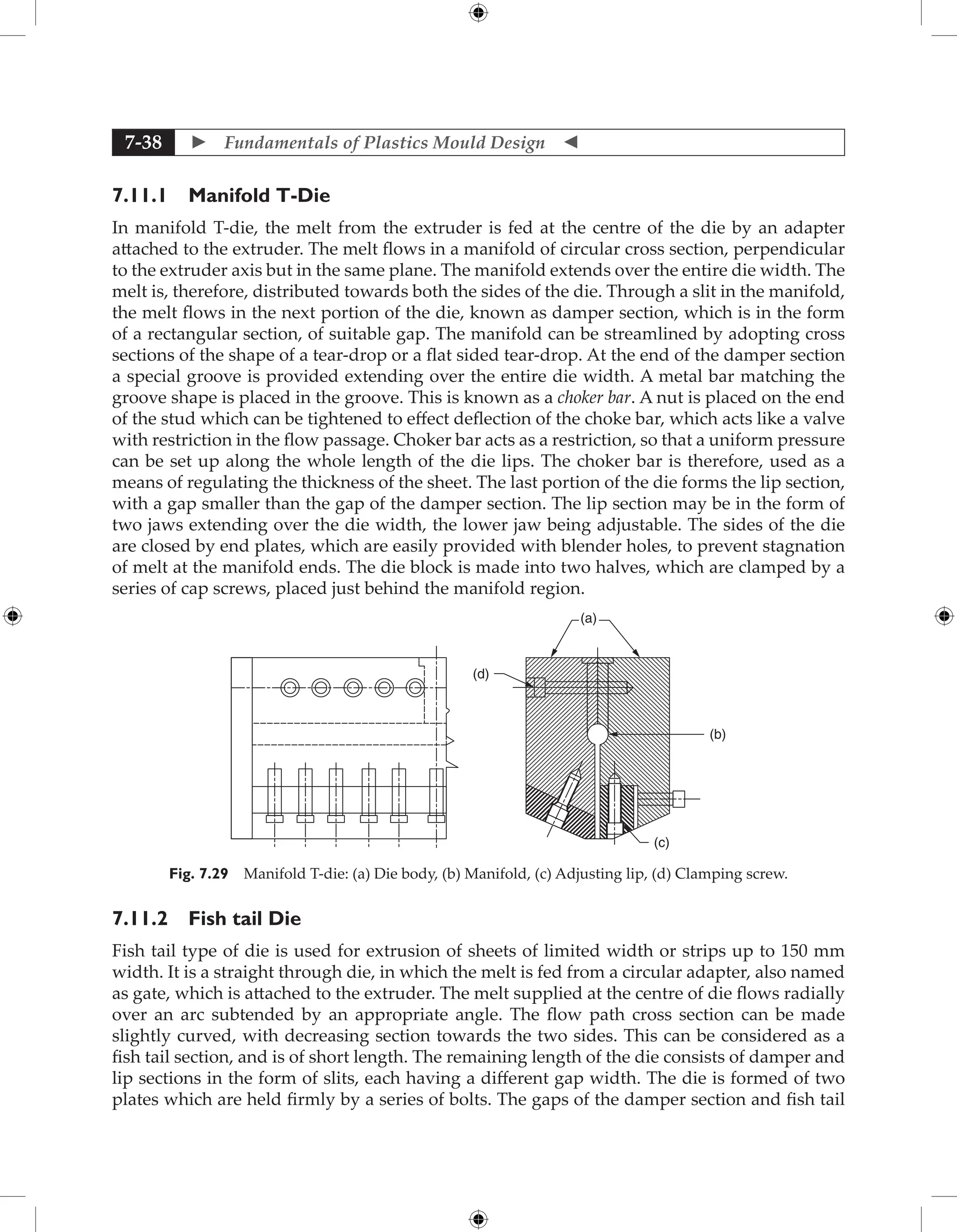
7.9.4 Offset Dies
Offset dies are used in certain special cases like production of pipes. The flow is diverted twice
by right angle to offset flow parallel to axis of extruder.
(a)
(b)
(d)
(c)
(e)
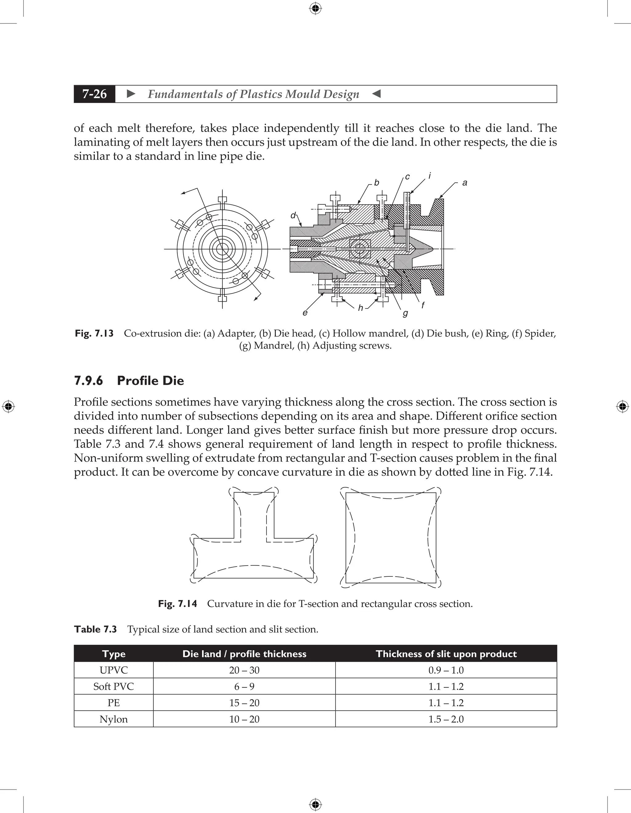
Fig. 7.12 Offset pipe die: (a) Die head, (b) Adapter, (c) Mandrel, (d) Die bush,
(e) Die ring.
7.9.5 Co-extrusion In-Line Pipe Die
Co-extrusion dies extrude pipes with two layers of different materials, by use of special dies,
which are fed from two separate extruders. The melts from the extruders are supplied to
different manifolds in the die. These manifolds are usually placed at an angle of 90°. One of the
manifolds is in line with one of the screw extruder, while the other feeds the material similar
to a cross-head die. The annular flow paths are therefore, provided around two concentric
mandrels. One of the flow paths is between the inner mandrel and the surrounding outer
mandrel and the other flow path is between the outer mandrel and the die body. The flow](https://image.slidesharecdn.com/fundamentalsofmoulddesign-231217032858-869d3d7e/75/Fundamentals-of-Mould-Design-lecture-pdf-529-2048.jpg)
![ Fundamentals of Plastics Mould Design
7-44
7.14.2 Low Voltage Resistance Heating
It requires a low voltage electric supply and the heating element made from the relatively
thick wire which has a high specific resistance. The wire is formed into a shape such as a coil
or a zigzag, which can be either located within the die or surrounding it.
7.14.3 Induction Heating
Induction heating is the process in which the heat generated in eddy currents induced by
an alternating current which generates an alternating magnetic field around the conductor.
The heating element consists of a heavy gauge copper wire wound into a former and bound
with tape to form a coil of convenient size. The coil is embedded in or located around the die.
When an alternating current is passed through the coil, eddy currents are included in the die,
resulting in heat generation.
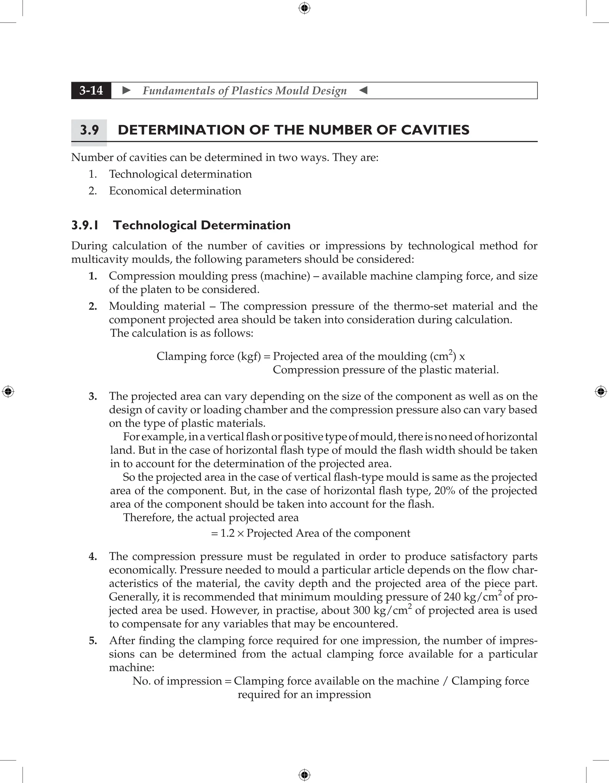
7.14.4 Design of Electric Heaters
The electric heaters used in dies are in the shape of a strip, clamp or cartridge; their capacities
are based on watt density, which is the wattage per unit area. To assess the capacity of
heaters for a die, the amount of heat for bringing the die to the operating temperature in the
required time is primarily determined. Secondly, the amount of heat necessary to maintain
the operating temperature is also determined. Whichever of the two is large will decide the
heater size.
1. Required capacity for bringing the die up to the operating temperature (Ha):
HA = Weight of the die × Specific heat of die material × Rise in temperature
= WDCP (t1 – t2) kilocalories (Kcal)
WD = Weight in kg
CP = Specific heat in Kcal/°C/kg where, t1 and t2 in °C.
If the time required to attain the operating temperature (t1) is T (hours),
then, heater capacity (K.W) (for heating of die) = HA / T × 860
2. Heat losses (HL): Losses due to convection and radiation. If the surface area of the die
is calculated, kilowatts lost through convection and radiation can be calculated. Since the die
is attached to the extruder, losses due to conduction may be neglected.
Average loss during heating up of the die = HL / 2
Heater capacity (K.W.) = (HL / 2 ) / 860
So, heater capacity for bringing the die up to the operating temperature,
including losses (K.W.)
[A] = (HA + HL/2) / 860
Total losses during operation (K.W.) [B] = HL / 860](https://image.slidesharecdn.com/fundamentalsofmoulddesign-231217032858-869d3d7e/75/Fundamentals-of-Mould-Design-lecture-pdf-548-2048.jpg)


![PowerISO 9.2 Mac Crack + Serial Key Free Download 2026 [Latest] Software.pptx](https://cdn.slidesharecdn.com/ss_thumbnails/software-251207185653-5d5700e6-thumbnail.jpg?width=640&height=640&fit=bounds)


![AnyTrans for iOS 8.9.14.20251127 With Crack for MacOS [Latest] pptx](https://cdn.slidesharecdn.com/ss_thumbnails/softwareoverview-251207190907-2316965f-thumbnail.jpg?width=640&height=640&fit=bounds)
![WinRAR Crack 7.13 Final Mac Keygen 2026 Download [Latest] Software.pptx](https://cdn.slidesharecdn.com/ss_thumbnails/software-251207185858-eb450678-thumbnail.jpg?width=640&height=640&fit=bounds)

![Moho Pro 14.4 Crack for MacOS Works Until 2050 [Latest] pptx](https://cdn.slidesharecdn.com/ss_thumbnails/softwareoverview-251207192639-797289c4-thumbnail.jpg?width=640&height=640&fit=bounds)


