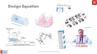
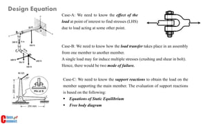
1. The document discusses the development of design equations for machine members.
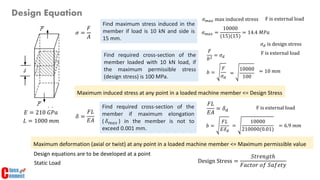
2. Maximum induced stress at any point in a loaded machine member must be less than or equal to the design stress. Maximum deformation must also be less than the maximum permissible value.
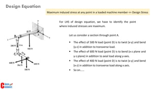
3. Developing design equations requires identifying the point of maximum stress and considering how loads are transferred between members in an assembly.
2. 𝜎 =
𝐹
𝐴
𝜎 𝑚𝑎𝑥 =
10000
(15)(15)
= 14.4 𝑀𝑃𝑎
Find maximum stress induced in the
member if load is 10 kN and side is
15 mm.
Find required cross-section of the
member loaded with 10 kN load, if
the maximum permissible stress
(design stress) is 100 MPa.
𝜎 𝑚𝑎𝑥 max induced stress F is external load
Find required cross-section of the
member if maximum elongation
( 𝛿 𝑚𝑎𝑥 ) in the member is not to
exceed 0.001 mm.
𝑏 =
𝐹
𝜎 𝑑
𝜎 𝑑 is design stress
F is external load
= 10 𝑚𝑚
𝛿 =
𝐹𝐿
𝐸𝐴
𝑏 =
𝐹𝐿
𝐸𝛿 𝑑
𝐸 = 210 𝐺𝑃𝑎
𝐿 = 1000 𝑚𝑚
F is external load
= 6.9 𝑚𝑚
Design Equation
=
10000
100
=
10000
210000(0.01)
𝐹
𝑏2
= 𝜎 𝑑
Maximum induced stress at any point in a loaded machine member <= Design Stress
𝐹𝐿
𝐸𝐴
= 𝛿 𝑑
Maximum deformation (axial or twist) at any point in a loaded machine member <= Maximum permissible value
Design equations are to be developed at a point
Design Stress =
𝑆𝑡𝑟𝑒𝑛𝑔𝑡ℎ
𝐹𝑎𝑐𝑡𝑜𝑟 𝑜𝑓 𝑆𝑎𝑓𝑒𝑡𝑦Static Load
3. Design Equation
For LHS of design equation, we have to identify the point
where induced stresses are maximum.
Let us consider a section through point A.
The effect of 500 N load (point D) is to twist (x-y) and bend
(y-z) in addition to transverse load.
The effect of 600 N load (point D) is to bend (x-z plane and
y-z plane) in addition to axial load along y-axis.
The effect of 400 N load (point D) is to twist (x-y) and bend
(x-z) in addition to transverse load along x axis.
So on……
Maximum induced stress at any point in a loaded machine member <= Design Stress
6. Case-C: We need to know the support reactions to obtain the load on the
member supporting the main member. The evaluation of support reactions
is based on the following:
Equations of Static Equilibrium
Free body diagram
Case-A: We need to know the effect of the
load at point of interest to find stresses (LHS)
due to load acting at some other point.
Design Equation
Case-B: We need to know how the load transfer takes place in an assembly
from one member to another member.
A single load may for induce multiple stresses (crushing and shear in bolt).
Hence, there would be two mode of failure.