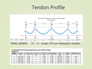
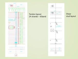
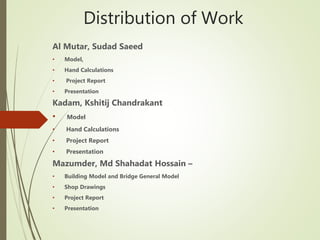
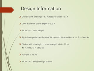
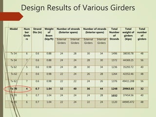
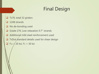
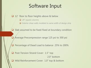
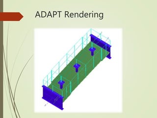
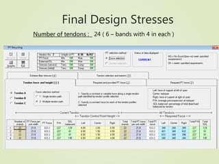
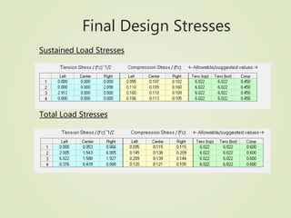
Prestressed Concrete
(CE 5309)
Term Project
Group 2
Spring 2016
University of Texas at Arlington
PART 1
PRE-TENSIONED PRESTRESSED BRIDGE
DESIGN
IH-35W Bridge 205
Design Information
 Overall width of bridge = 53 ft; roadway width = 51 ft
 Limit maximum Girder length to 120 ft
 TxDOT T551 rail – 382 plf
 Typical composite cast-in-place deck with 8” thick and f’c= 4 ksi, Ec = 3605 ksi
 Girders with ultra-high concrete strength – f’ci = 20 ksi,
f’c = 30 ksi, Ec = 9872 ksi
 PGSuper V 2.9.0.9
 TxDOT 2013 Bridge Design Manual
 Geometry
 8 Number of spans
 Exterior spans - 105 ft.
 Interior spans - 115.06 ft.
 Tx70 girders selected
 Most economical
 Least weight
 Least number of girders
 4 girders spaced at 16' on center
Design Parameters
PGSuper Model
Strand Layout, Span 8 Girder A
Section @ Mid-SpanSection @ Left-End Section @ ¼ Span
Shear Layout
Concrete Strength
Deck Properties and Overlay
Weight
Design Results of Various Girders
Model Num
ber
Girde
rs
Strand
Dia (in)
Weight
of
Beam
(kip/ft)
Number of strands
(Exterior spans)
Number of strands
(Interior spans)
Total
Number
of
Strands
Total
weight of
girders
(kips)
Total
number
of
girdersExternal
Girders
Internal
Girders
External
Girders
Internal
Girders
Tx 54 6 0.6 0.88 24 28 30 34 1496 38030.78 48
Tx 54 7 0.6 0.88 24 24 28 30 1572 44369.25 56
Tx 62 5 0.6 0.98 24 28 30 34 1236 35293.72 40
Tx 62 6 0.6 0.98 22 24 26 28 1264 42352.46 48
Tx 62 7 0.6 0.98 22 22 24 26 1376 49411.208 56
Tx 70 4 0.7 1.04 32 40 36 44 1248 29963.65 32
Tx 70 5 0.7 1.04 24 24 24 28 1032 37454.56 40
Tx 70 6 0.7 1.04 22 24 22 24 1120 44945.472 48
Final Design
 Tx70, total 32 girders
 1248 strands
 No de-bonding used
 Grade 270, Low-relaxation 0.7" strands
 Additional mild steel reinforcement used
 TxDot standard details used for shear design
 f‘ci = 20 ksi, f‘c = 30 ksi
Distribution of L.L for span 8
• From hand calculation = 1.256
• Difference = 8.7%
Moment Capacity at Mid-span
Exterior Girder – End Span
Comparison of Multiple Loads Moments
And Moment Capacity
Comparison of Multiple Loads
Shear And Shear Capacity
Multiple Loads Displacement
Ahmed, Haroon Rasheed
 Girder Design (Tx 40 and 46)
 Drawings,
 PowerPoint Presentation
Bichewar, Namrata
 Girder Design ( Tx 70)
 Live Load Moment Distribution Factor
Emami Saleh, Arash (Team Leader)
 General Model
 Moment Calculations,
 PowerPoint Presentation
Okagbare, Oghenekevwe Christabel (Team Leader)
 Girder Design ( Tx 28 and Tx 34)
 Drawings
 Project Report
 PowerPoint Presentation
Shaltoof, Mohammad Abed Mohammad
 Girder Design( Tx 54 and 62)
 Moment Calculations
 PowerPoint Presentation
Distribution of Work
PART 2
POST-TENSIONED TWO-WAY SLAB DESIGN
Overall Second Level Plan
Design Parameters
Concrete Properties
 Slab Thickness = 8 inches
 F’c = 4,000 psi, Ec = 3605 ksi
Prestressed Steel Properties
 ½” dia. Grade 270 low-relaxation strands
 Initial Prestress = 0.8 * fpu
Loading
 Superimposed Dead Load = 20 psf
 Superimposed Live Load = 40 psf
ACI 318-11 used as design code
Design Consideration
 4 – span condition utilizing wall as an exterior
support
 Equivalent Frame Method
 Software Inputs
Software Input
 12’ floor to floor heights above & below
 24” square columns
 Exterior shear walls modeled to same width of design strip
 Slab assumed to be fixed-fixed at boundary condition
 Average Precompression range 125 psi to 300 psi
 Percentage of Dead Load to balance 25% to 200%
 Post-Tension Strand Cover: 1.5” top
2.0” bottom
 Mild Reinforcement Cover: 1.0” top & bottom
Tributary Area
Tributary Area (Cont…)
Loading on the slab
ADAPT Rendering
Final Design Stresses
Max Tensile Stress = 0 x √(f’ci) < 3 x √(f’ci) OK
Max Compressive Stress = 0.164 x f’ci < 0.6 x f’ci OK
Number of tendons : 24 ( 6 – bands with 4 in each )
Final Design Stresses
Sustained Load Stresses
Total Load Stresses
Stress Diagram
-450
-400
-350
-300
-250
-200
-150
-100
-50
0
50
100
150
200
SPAN1 SPAN2 SPAN3 SPAN4
Stress Diagrams
Project: "TermProject" / LoadCase:SERVICE_1_Max_LL
+1.00SW+0.30LL_Max+1.00SDL+0.30XL +1.00 PT +0.00HYP+0.00LAT
Tensile Stress Positive
Stress[psi]
AllowableStresses Top
Tendon Profile
FINAL DESIGN: 15 – ½”, Grade 270 Low-Relaxation strands
Mild Steel Profile
Tendon layout
24 strands – 4/band
Shear
stud layout
Distribution of Work
Al Mutar, Sudad Saeed
• Model,
• Hand Calculations
• Project Report
• Presentation
Kadam, Kshitij Chandrakant
• Model
• Hand Calculations
• Project Report
• Presentation
Mazumder, Md Shahadat Hossain –
• Building Model and Bridge General Model
• Shop Drawings
• Project Report
• Presentation

Final Presentation - Group 2 (1)

  • 1.
    Prestressed Concrete (CE 5309) TermProject Group 2 Spring 2016 University of Texas at Arlington
  • 2.
  • 3.
  • 4.
    Design Information  Overallwidth of bridge = 53 ft; roadway width = 51 ft  Limit maximum Girder length to 120 ft  TxDOT T551 rail – 382 plf  Typical composite cast-in-place deck with 8” thick and f’c= 4 ksi, Ec = 3605 ksi  Girders with ultra-high concrete strength – f’ci = 20 ksi, f’c = 30 ksi, Ec = 9872 ksi  PGSuper V 2.9.0.9  TxDOT 2013 Bridge Design Manual
  • 5.
     Geometry  8Number of spans  Exterior spans - 105 ft.  Interior spans - 115.06 ft.  Tx70 girders selected  Most economical  Least weight  Least number of girders  4 girders spaced at 16' on center Design Parameters
  • 6.
  • 7.
    Strand Layout, Span8 Girder A Section @ Mid-SpanSection @ Left-End Section @ ¼ Span
  • 8.
  • 9.
  • 10.
    Deck Properties andOverlay Weight
  • 11.
    Design Results ofVarious Girders Model Num ber Girde rs Strand Dia (in) Weight of Beam (kip/ft) Number of strands (Exterior spans) Number of strands (Interior spans) Total Number of Strands Total weight of girders (kips) Total number of girdersExternal Girders Internal Girders External Girders Internal Girders Tx 54 6 0.6 0.88 24 28 30 34 1496 38030.78 48 Tx 54 7 0.6 0.88 24 24 28 30 1572 44369.25 56 Tx 62 5 0.6 0.98 24 28 30 34 1236 35293.72 40 Tx 62 6 0.6 0.98 22 24 26 28 1264 42352.46 48 Tx 62 7 0.6 0.98 22 22 24 26 1376 49411.208 56 Tx 70 4 0.7 1.04 32 40 36 44 1248 29963.65 32 Tx 70 5 0.7 1.04 24 24 24 28 1032 37454.56 40 Tx 70 6 0.7 1.04 22 24 22 24 1120 44945.472 48
  • 12.
    Final Design  Tx70,total 32 girders  1248 strands  No de-bonding used  Grade 270, Low-relaxation 0.7" strands  Additional mild steel reinforcement used  TxDot standard details used for shear design  f‘ci = 20 ksi, f‘c = 30 ksi
  • 13.
    Distribution of L.Lfor span 8 • From hand calculation = 1.256 • Difference = 8.7%
  • 14.
    Moment Capacity atMid-span Exterior Girder – End Span
  • 17.
    Comparison of MultipleLoads Moments And Moment Capacity
  • 18.
    Comparison of MultipleLoads Shear And Shear Capacity
  • 19.
  • 20.
    Ahmed, Haroon Rasheed Girder Design (Tx 40 and 46)  Drawings,  PowerPoint Presentation Bichewar, Namrata  Girder Design ( Tx 70)  Live Load Moment Distribution Factor Emami Saleh, Arash (Team Leader)  General Model  Moment Calculations,  PowerPoint Presentation Okagbare, Oghenekevwe Christabel (Team Leader)  Girder Design ( Tx 28 and Tx 34)  Drawings  Project Report  PowerPoint Presentation Shaltoof, Mohammad Abed Mohammad  Girder Design( Tx 54 and 62)  Moment Calculations  PowerPoint Presentation Distribution of Work
  • 21.
  • 22.
  • 23.
    Design Parameters Concrete Properties Slab Thickness = 8 inches  F’c = 4,000 psi, Ec = 3605 ksi Prestressed Steel Properties  ½” dia. Grade 270 low-relaxation strands  Initial Prestress = 0.8 * fpu Loading  Superimposed Dead Load = 20 psf  Superimposed Live Load = 40 psf ACI 318-11 used as design code
  • 24.
    Design Consideration  4– span condition utilizing wall as an exterior support  Equivalent Frame Method  Software Inputs
  • 25.
    Software Input  12’floor to floor heights above & below  24” square columns  Exterior shear walls modeled to same width of design strip  Slab assumed to be fixed-fixed at boundary condition  Average Precompression range 125 psi to 300 psi  Percentage of Dead Load to balance 25% to 200%  Post-Tension Strand Cover: 1.5” top 2.0” bottom  Mild Reinforcement Cover: 1.0” top & bottom
  • 26.
  • 27.
  • 28.
  • 29.
  • 30.
    Final Design Stresses MaxTensile Stress = 0 x √(f’ci) < 3 x √(f’ci) OK Max Compressive Stress = 0.164 x f’ci < 0.6 x f’ci OK Number of tendons : 24 ( 6 – bands with 4 in each )
  • 31.
    Final Design Stresses SustainedLoad Stresses Total Load Stresses
  • 32.
    Stress Diagram -450 -400 -350 -300 -250 -200 -150 -100 -50 0 50 100 150 200 SPAN1 SPAN2SPAN3 SPAN4 Stress Diagrams Project: "TermProject" / LoadCase:SERVICE_1_Max_LL +1.00SW+0.30LL_Max+1.00SDL+0.30XL +1.00 PT +0.00HYP+0.00LAT Tensile Stress Positive Stress[psi] AllowableStresses Top
  • 33.
    Tendon Profile FINAL DESIGN:15 – ½”, Grade 270 Low-Relaxation strands
  • 34.
  • 35.
    Tendon layout 24 strands– 4/band Shear stud layout
  • 36.
    Distribution of Work AlMutar, Sudad Saeed • Model, • Hand Calculations • Project Report • Presentation Kadam, Kshitij Chandrakant • Model • Hand Calculations • Project Report • Presentation Mazumder, Md Shahadat Hossain – • Building Model and Bridge General Model • Shop Drawings • Project Report • Presentation