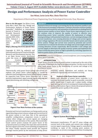
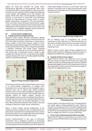
The article presents a design and performance analysis of a power factor controller aimed at improving power quality in electrical systems in Myanmar. It explores various components such as potential and current transformers, microcontroller systems, and relay drivers to enhance power factor by switching capacitors. The system has been simulated and evaluated, demonstrating acceptable results in controlling power quality under load conditions.
![International Journal of Trend in Scientific Research and Development (IJTSRD) @ www.ijtsrd.com eISSN: 2456-6470
@ IJTSRD | Unique Paper ID – IJTSRD27821 | Volume – 3 | Issue – 5 | July - August 2019 Page 2061
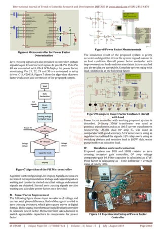
V. Discussion and evaluation
Efficiency of DC power supply is acceptable enough to drive
the controller and to supply zero crossing detectors. Zener
regualtion and capacitor filter circuits are also working in
goog manner. PIC microcontroller input output and timing
are all seamlessly set up. In the system relay drivers work
well but no security and safety for relay driver and
capacitors switching.
VI. CONCLUSION
Power factor controller is good for using witch capacitor
bank where several inductive load utilizing places, as
inducstrial and enterprise.
Acknowledgment
Author would like to acknowledge, Minister of Education,
Rector of Pyay Technological University, faculties of
DepartmentofElectrical PowerEngineering,colleagues from
Power Electronics and Device Control Engineering Division,
Parents, especially dedicated to my wife and son.
References
[1] Zin Mar Soe, Mar.2017. Design and Implementation of
Static Frequency Converter for Aircraft Power System,
ME Thesis, Mandalay Technological University.
[2] [18Ara] Ararso,“DesignandSimulationofAutomatic
Power Factor Correction for Industry Application”
International Journal of Engineering Technology and
Management Research (IJETMR), Volume 5, Issue 2 ,
February 2018.
[3] [17Sai] SAIRAJ GHARAT1, DARSHANA
PATILKHEDE2, SANKET PATIL3,ABHISHEK YADAV4,
“Automatic Power Factor Correction Using
Microcontroller” International Journal of Engineering
Technology Science and Research (IJETSR), Volume 4,
Issue 4,April 2017.
[4] [16Bho] Prof. J. C Bhola, Prof. Pragti Jyotishi,
“Reactive Power Compensation in 132kV&33kV Grid of
Narsinghpur Area”, International Journal of
Computation Engineering Research (IJCER), Volume6,
Issue 6, June 2016.
[5] [15Ano] Anonymous, Datasheet and Guide Book of
PIC 18F4550 Microcontroller,
www.alldatasheet.com/PIC, 2015.
[6] [14Ana] Mr.Anant Kumar Tiwari, Mrs. Durga
Sharma, Mr.Vijay Kumar Sharma “Power Factor
Correction Using Capacitive Bank ”,Int. Journal of
Engineering Research and Applications ISSN : 2248-
9622, Vol. 4, Issue 2(Version 1), pp.393-395, February
2014.
[7] [13Akw] Akwukwaegbu I. O, Okwe Gerald Ibe,
“Concepts of Reactive power Control and Voltage
Stability Methods in Power System Network”, Journal of
Computer Engineering (IOSR-JCE) Volume 11, Issue
2,(May-Jun 2013).](https://image.slidesharecdn.com/392designandperformanceanalysisofpowerfactorcontroller-190917124303/85/Design-and-Performance-Analysis-of-Power-Factor-Controller-4-320.jpg)