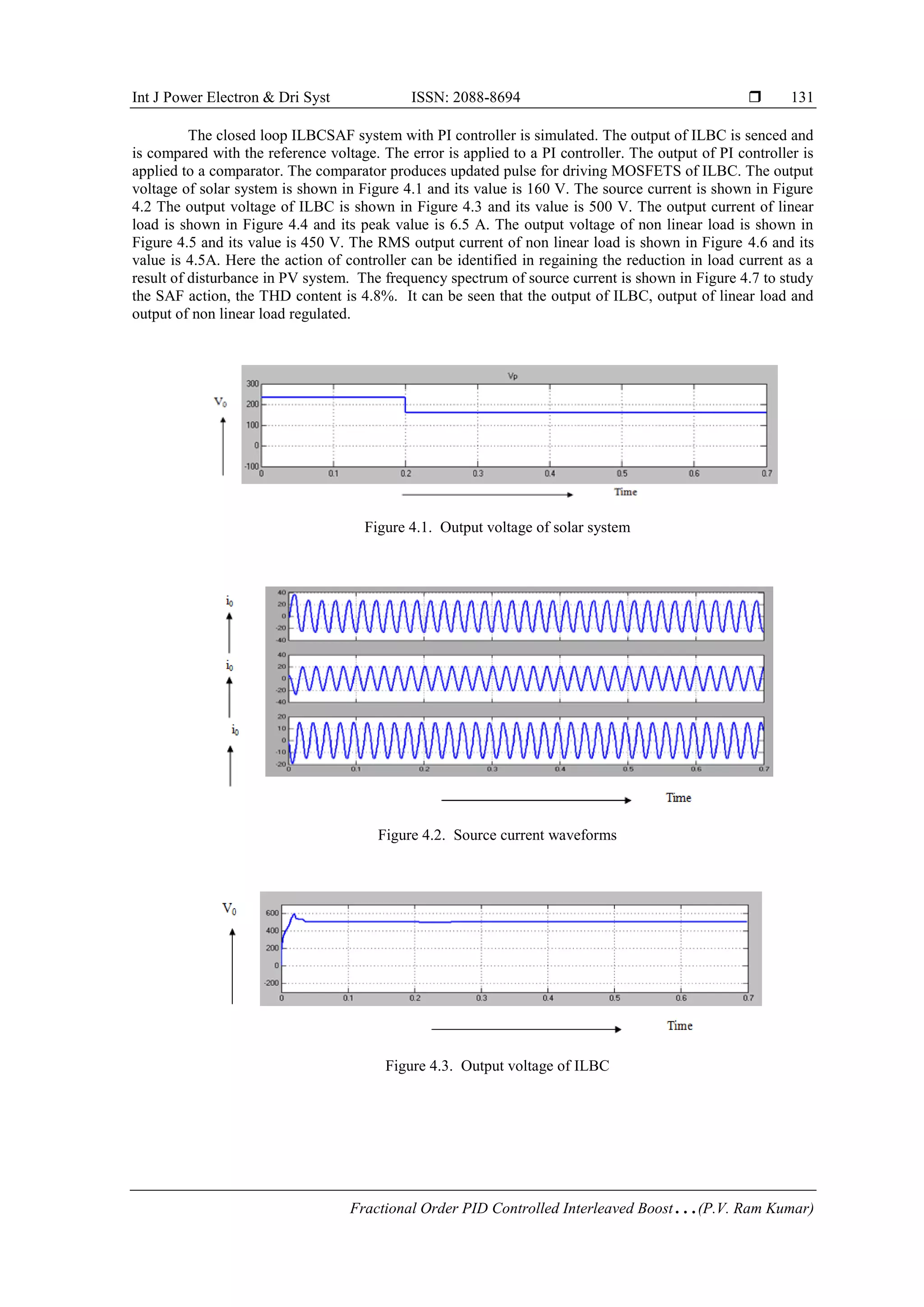
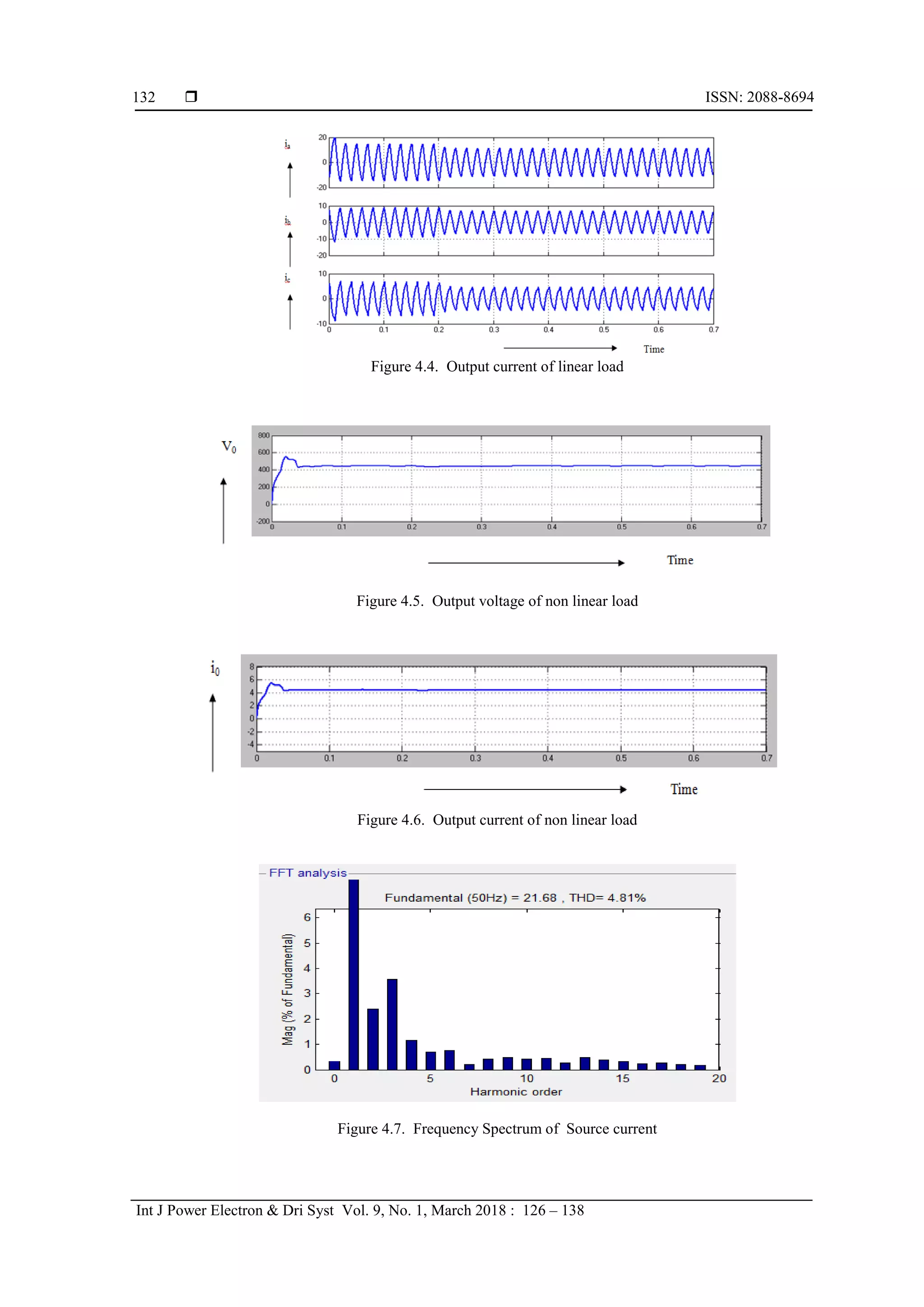
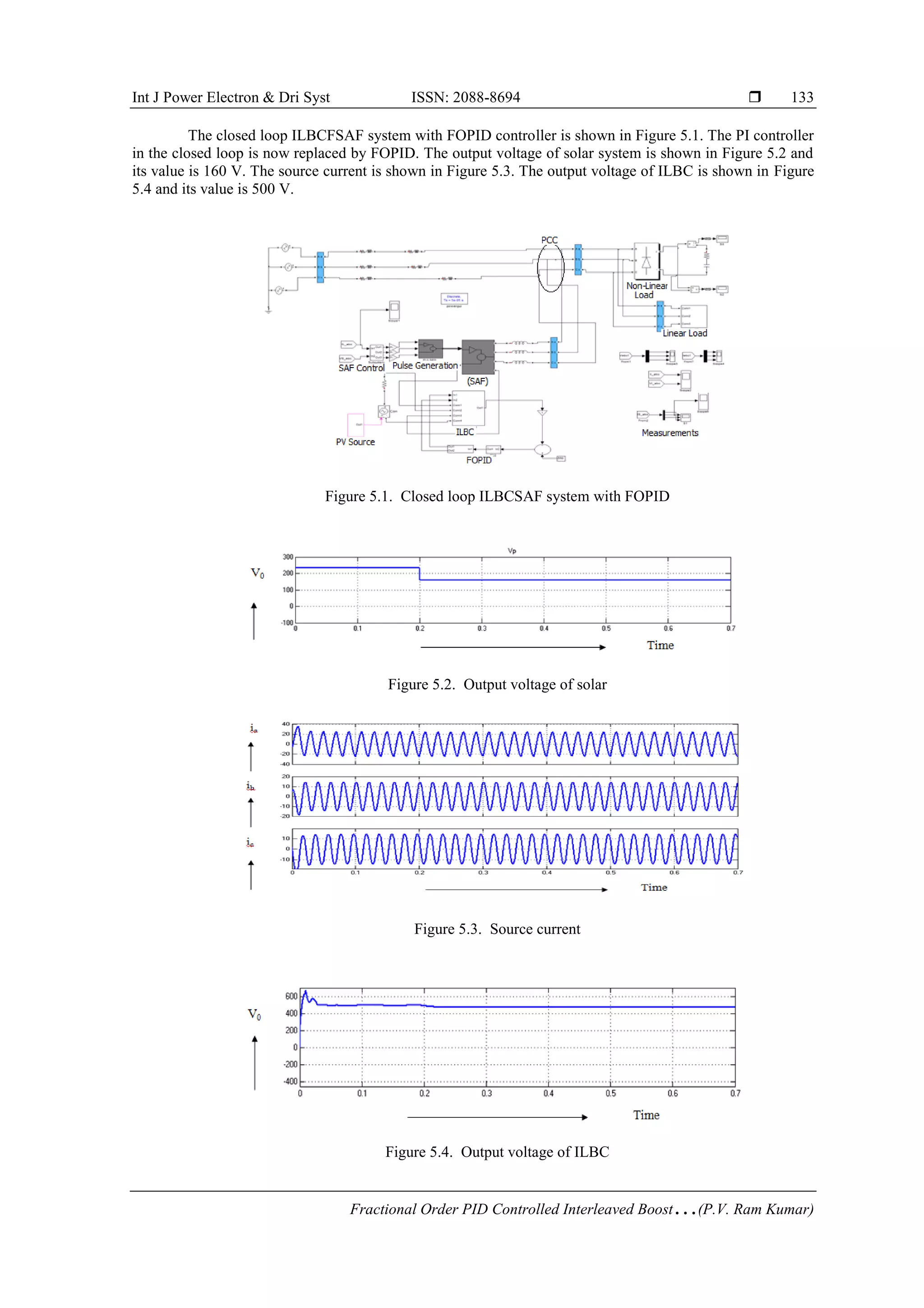
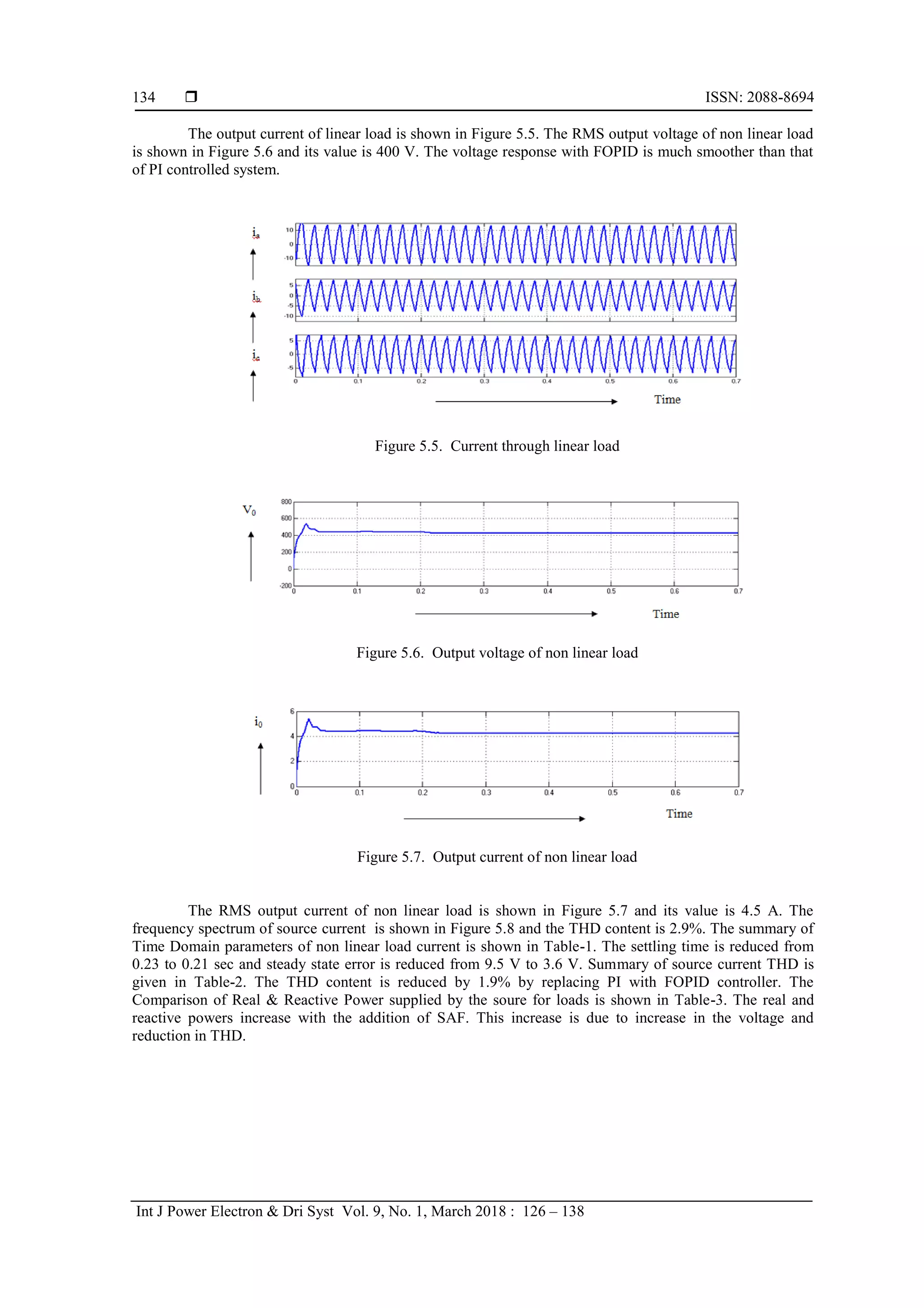
The document presents the development and analysis of a fractional order PID (FOPID) controlled interleaved boost converter (ILBC) used in a grid-connected photovoltaic (PV) system to improve the performance of a shunt active filter. It highlights the advantages of the FOPID controller over traditional controllers in minimizing current ripple and enhancing dynamic responses, with simulation and hardware results demonstrating its effectiveness. The research shows significant improvements in parameters such as settling time and total harmonic distortion (THD) when using the FOPID controller compared to conventional PI control.
![International Journal of Power Electronics and Drive System (IJPEDS)
Vol. 9, No. 1, March 2018, pp. 126~138
ISSN: 2088-8694, DOI: 10.11591/ijpeds.v9.i1.pp126-138 126
Journal homepage: http://iaescore.com/journals/index.php/IJPEDS
Fractional Order PID Controlled Interleaved Boost converter
Fed Shunt Active Filter System
P. V. Ram Kumar1
, M. Surya Kalavathi2
1
Department of Electrical and Electronics Engineering, JNTU, Ananthapuramu
2
Department of Electrical and Electronics Engineering, J.N.T.U. College of Engg, Hyderabad, India
Article Info ABSTRACT
Article history:
Received May 25, 2017
Revised Dec 22, 2017
Accepted Jan 1, 2018
Interleaved Boost Converter (ILBC) is a better converter between Photo
Voltaic (PV) source and shunt active power filter. This paper deals with
comparison of time domain outputs of PI and Fractional Order PID(FOPID)
controlled ILBC fed shunt active filter in a grid connected PV system. The
aim of this work is to minimize current ripple using ILBC between PV
system and filter to improve the dynamic performance of shunt active filter.
Closed loop monitored PI and FOPID systems are modeled, and the
corresponding results are presented. MATLAB results of load voltage,
current, converter voltage and currents with FOPID exhibits enhanced
dynamic response. The proposed FOPID controlled ILBC Fed Shunt Active
Filter system (ILBCFSAF) has advantages like low settling time, less peak
over shoot and reduced steady state error in load voltage. The simulation
results of ILBCFSAF are compared with the corresponding hardware results.
Keyword:
FOPID Controller
Interleaved Boost Converter
Non linear load
Shunt Active Filter
Copyright © 2018 Institute of Advanced Engineering and Science.
All rights reserved.
Corresponding Author:
P. V. Ram Kumar,
Departement of Electrical and Electronics Engineering,
JNT University,
Ananthapuramu, India
Email: ramkumar_pv@yahoo.co.in
1. INTRODUCTION
Distribution sources such as Photo-Voltaic (PV) generation system, and wind power systems have
become popular since they are green power source. The DC-AC inverter can be used as Shunt Active
Filter(SAF) whose output is controlled by pulses to convert dc power of PV into ac and to inject equivalent
currents to compensate harmonics. The pulses are produced by a controller which monitors the deviation
between system voltage and input dc voltage of converter. Conventionally PI or PID controllers are used for
this purpose but suffer from frequent tuning of their parameters for different load and disturbance conditions.
The step up converters have drawbacks of low voltage gain and low power rating. Interleaved Boost
converter has reduced ripple currents in both the input and output sides.
Different steps involved in design of MPPT controller and evaluation of the need of storage devices,
load take off strategies of PV system is presented in [1]. Effect of partial shading on building Integrated PV
systems, causes and mitigation techniques using software and hard ware solutions is presented in [2]. A
fractional-order PID (FOPID) controller is designed in[3] to control a DC-DC boost converter in a PV-
system. To obtain the best system performance, parameters of the proposed controller are tuned by using
Particle Swarm Optimization (PSO) algorithm. Analysis and hardware implementation of two phase ILBC is
proposed in [4] where in design of magnetic component i.e., inductor is studied. High gain four stage ILBC is
proposed in [5] which is a combination of two 2 phase interleaved boost converters to obtain smooth output
ripple current, increase in power rating and efficiency. Basic concepts regarding design of ILBC which
involves selection of inductors, input and output capacitors, power switches etc., was given in[6]. As far as
the controlling of SAF is concerned, the Instantaneous Power Theory (IPT) and its application to power](https://image.slidesharecdn.com/1522dec1725may177228pidrevisededitern-210610040215/75/Fractional-Order-PID-Controlled-Interleaved-Boost-converter-Fed-Shunt-Active-Filter-System-1-2048.jpg)
![Int J Power Electron & Dri Syst ISSN: 2088-8694
Fractional Order PID Controlled Interleaved Boost…(P.V. Ram Kumar)
127
conditioning given by Akagi [7] is the basis for SAF. A detailed review of SAF with respect to control
techniques and topology is presented by Bhimsingh[8].A method to evaluate the performance of utility
interactive PV system is given by Abouzahr[9]. The design of SAF with output LCL filter is given by
Tang[10]. The control algorithm of SAF for voltage regulation and PFC is depicted by Haddad[11]. A
selection methodology for the number of phases and analysis of the input current ripple with CCM and DCM
is for an ILBC is given in [12]. A study of various PV fed Active filters with respect to their circuit and
control methods is presented in [13]. To investigate various Power Quality issues such as THD, phase
imbalance and excessive neutral currents etc., a predictive control technique using FLC is proposed in [14]
where in FLC is applied for MPPT. A single-phase dual-stage PV-Grid system with active filtering capability
is constructed in [15] with simple circuits such as current transducer. The system used a boost chopper as
MPPT controller.
Lot of research on single stage PV grid-connected system with power quality improvement has been
done so far but not many studies are available on Boost Converter topologies used to boost the low
magnitude PV voltages. In this paper, a novel high capacity grid-connected PV system based on Interleaved
Boost converter fed Shunt active filter is proposed, which has reduced current ripple.The problem
formulation involves improving dynamic response of ILBCFSAF system. The pulse width applied to the
ILBC is adjusted to obtain constant voltage at the output. The FOPID is proposed to improve the dynamic
response.
The content of this paper is organized as follows: Section.2 deals with description of existing and
proposed system. Control schemes of the systems are described in the 3rd section. Simulation results are
described in section 4. A prototype model with hard ware components is developed, the details of which are
presented in section 5. The work is concluded in section 6.
2. DESCRIPTION OF THE PROPOSED SYSTEM
The block diagram of conventional SAF system is shown in Figure 1. The SAF is connected near
the non linear load.
Figure 1. Block diagram of conventional system Figure 2. Block Diagram of Proposed ILBCFSAF
System
Block diagram of the proposed ILBCFSAF system is shown in Figure.2. A three phase voltage
source inverter is made to work as SAF and is the key component of the system, dc required to charge the
capacitor of the SAF is obtained from ILBC. Actual voltage of this DC Link capacitor is compared. With the
reference voltage and the voltage error is applied to the FOPID. The output of the FOPID controls the pulse
width applied to ILBC.
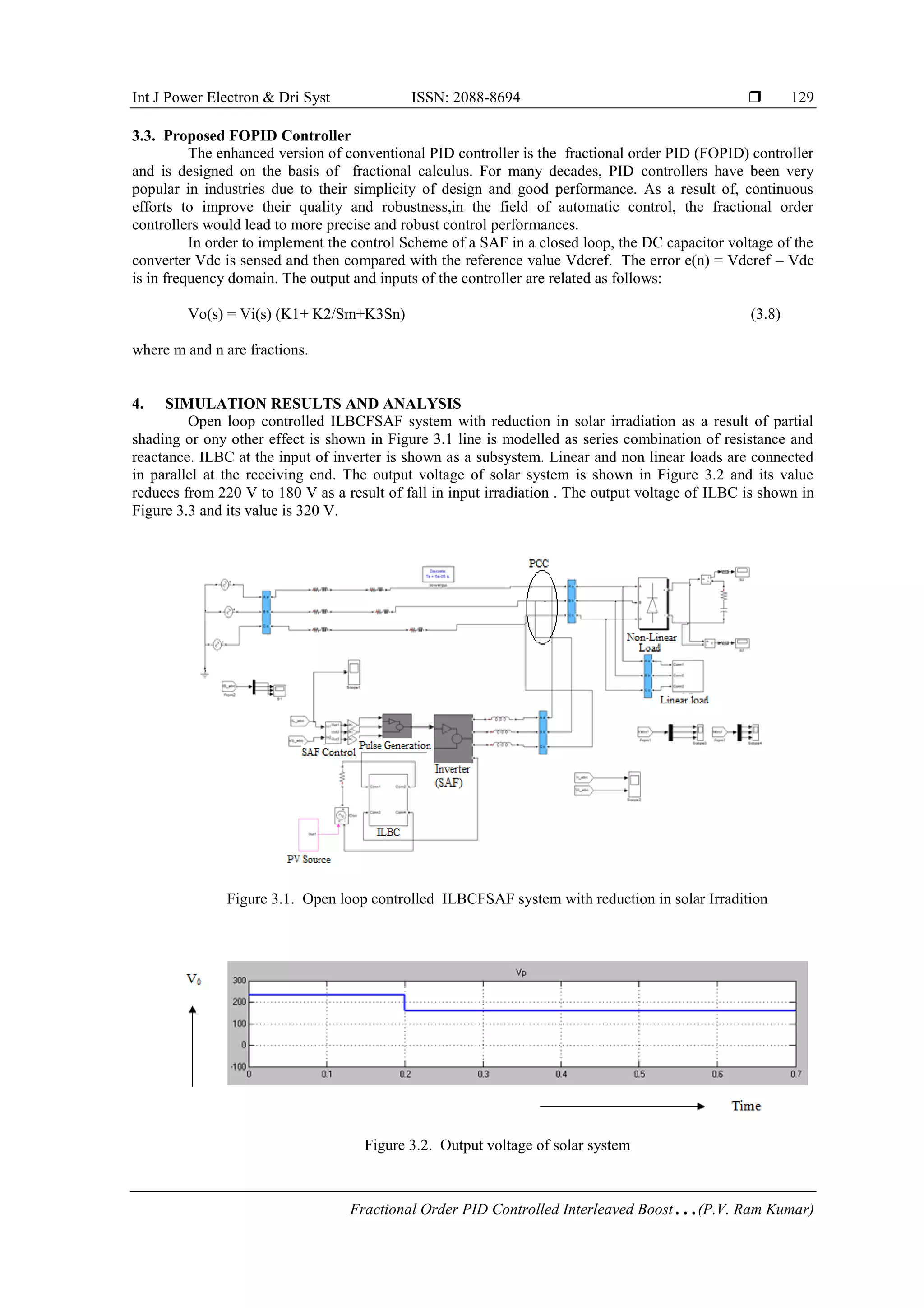
3. RESEARCH METHOD
3.1. Inter Leaved Boost Converter
ILBC overcomes the drawbacks of conventional boost converters, its static and dynamic
performances are poor. Hence, an effective control of these converters is needed. Though conventional PI or
PID controllers are useful, tuning of these for different loads is problematic. This paper proposes a fractional](https://image.slidesharecdn.com/1522dec1725may177228pidrevisededitern-210610040215/75/Fractional-Order-PID-Controlled-Interleaved-Boost-converter-Fed-Shunt-Active-Filter-System-2-2048.jpg)
![ ISSN: 2088-8694
Int J Power Electron & Dri Syst Vol. 9, No. 1, March 2018 : 126 – 138
128
order PID controller for controlling ILBC to derive good dynamic response of the load voltage. The circuit
diagram of ILBC is shown in Figure.3.
Figure 3. Circuit diagram of ILBC
The design considerations of ILBC are as follows
L and C for ILBC are determined using
L = Vi D f I
⁄ (3.1)
C = D 2. f. R
⁄ (3.2)
L1 and L2 works out to 130mH and C workout to 470µF
3.2. Control of SAF
p-q theory is used for controlling the three leg VSI inverter. As this thery is based on α-β-0 frameed
quantities, Conversion of source voltages and currents in to this frame is done using a transformation matrix
C.
[
v0
vα
vβ
] = C [
va
vb
vc
] ; [
i0
iα
iβ
] = C [
ia
ib
ic
] (3.3)
where C = √
2
3
[
1
√2
1
√2
1
√2
1 −
1
2
−
1
2
0
√3
2
−
√3
2 ]
(3.4)
The active and reactive power demanded by the load can be decomposed into
pL = pL
̅̅̅ + pL
̃ ; qL
= qL
̅̅̅̅ + qL
̃ (3.5)
The reference source currents in the α-β-0 frame are as follows:
[
isRf0
isRfα
isRfβ
] =
1
vα
2 +vβ
2 [
v0 0 vβ
vα −vβ 0
vβ vα −v0
−vα
v0
0
] × [
p
̅Lαβ + p
̅L0
0
0
0
] =
p
̅Lαβ +p
̅L0
vα
2 +vβ
2 [
0
vα
vβ
] (3.6)
Assuming Ls= 10mH, the capacitance of SAF is calculated by
fs = 1 2π√Ls Cs
⁄ (3.7)
Pulse width of inverter is found to be 0.66ms for a supply frequency of 50Hz.](https://image.slidesharecdn.com/1522dec1725may177228pidrevisededitern-210610040215/75/Fractional-Order-PID-Controlled-Interleaved-Boost-converter-Fed-Shunt-Active-Filter-System-3-2048.jpg)
![Int J Power Electron & Dri Syst ISSN: 2088-8694
Fractional Order PID Controlled Interleaved Boost…(P.V. Ram Kumar)
137
(a). Switching pulses for S1 and S3 (b). Switching pulses for S2 and S4
Figure 6.3. Switching pulses of inverter
Figure 6.4 Output voltage of SAF Figure.6.5. Output voltage of nonlinear load
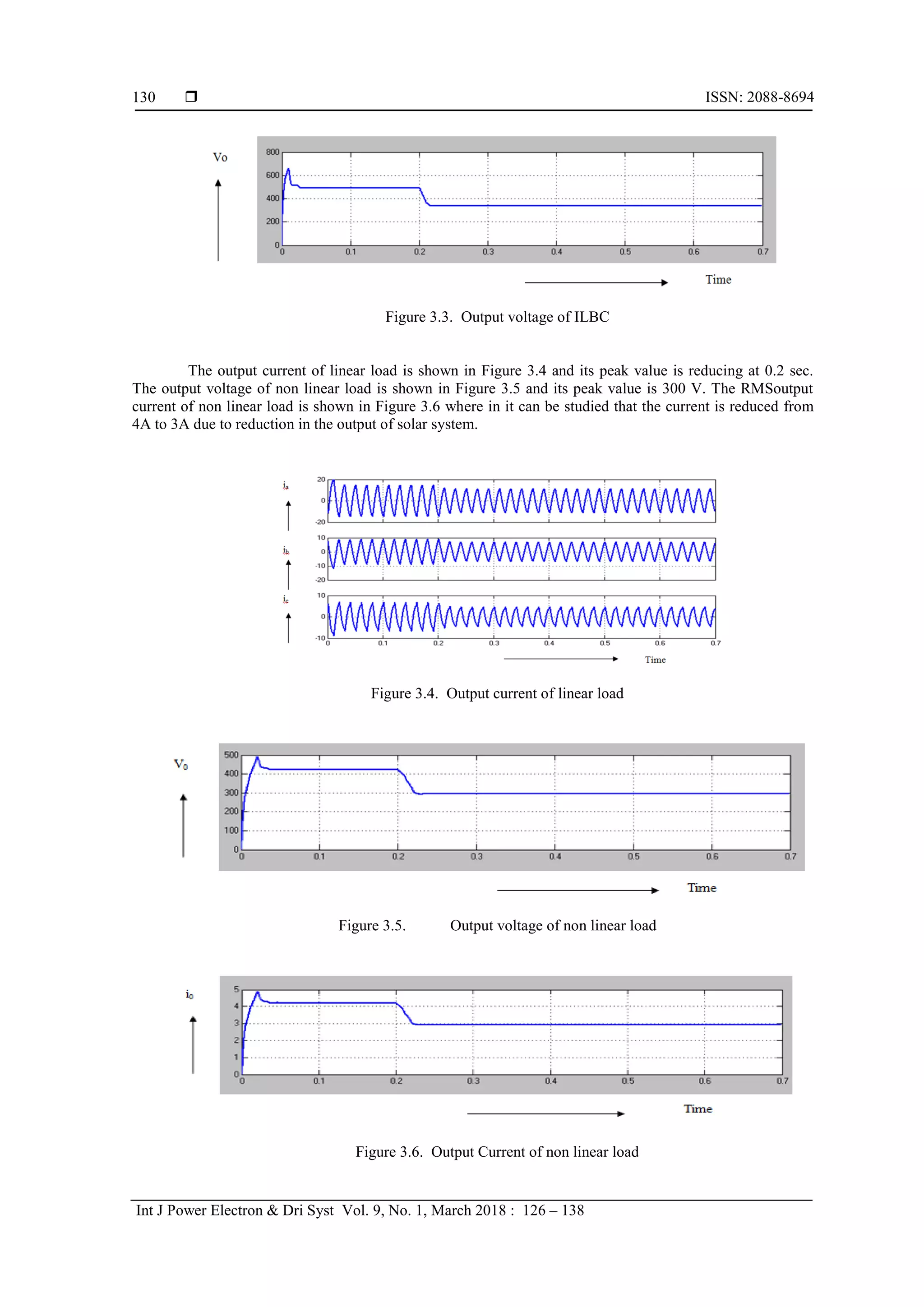
6. CONCLUSION
ILBCFSAF system controlled by PI and FOPID are modelled and simulated using SIMULINK. The
simulation results of PI and FOPID controllers are presented and analysed. The settling time with FOPID for
output voltage is 0.21 sec and steady state error in voltage is as low as 3.6V. Therefore the response of
FOPID based ILBCSAF system is better than that of PI controlled system. The advantages of proposed
system are low ripple content of PV voltage and current injected at PCC and improved time domain response
of load voltage.The disadvantage of proposed system is that hardware count of ILBC is twice that of normal
boost converter. This work deals with comparison PI and FOPID based ILBCFSAF systems.
REFERENCES
[1] BV Rajanna, SVNL Lalitha, G Joga Rao, S.K Shrivastav., “Solar Photovoltaic Generators with MPPT and Battery
Storage in Microgrids,” International Journal of Power Electronics and Drive System (IJPEDS), Vol. 7, No. 3, pp.
701-712, September 2016.
[2] Zainal Salam, Zulkifli Ramli, Jubaer Ahmed and Muhammad Amjad., “Partial Shading in Building Integrated PV
System: Causes, Effects and Mitigating Techniques,” International Journal of Power Electronics and Drive
System (IJPEDS), Vol. 6, No. 4, pp. 712-722, December 2015.
[3] Erdnic Sahin, Mustafa Sinasi Ayas,”A PSO optimized fractional-order PID controller for a PV system with DC-DC
boost converter,” 2014 16th International Power Electronics and Motion Control Conference and Exposition
(PEMC), Antalya, Turkey.](https://image.slidesharecdn.com/1522dec1725may177228pidrevisededitern-210610040215/75/Fractional-Order-PID-Controlled-Interleaved-Boost-converter-Fed-Shunt-Active-Filter-System-12-2048.jpg)
![ ISSN: 2088-8694
Int J Power Electron & Dri Syst Vol. 9, No. 1, March 2018 : 126 – 138
138
[4] Nasir Coruh, Satilmis Urgun, Tarik Erfidan, Semra Ozturk.,” A Simple And Efficient Implemantation Of
Interleaved Boost Converter” 978-1-4244-8756-1/11/$26.00 c2011 IEEE.
[5] Weerachat Khadmun and Wanchai Subsingha., “High Voltage Gain Interleaved DC Boost Converter Application
for photo voltaic System” 10th Eco-Energy and Materials Science and Engineering(EMSES2012), Elsevier,Energy
procedia 34, pp.390 – 398, 2013.
[6] “AN-1820 LM5032 Interleaved Boost Converter” Texas Instruments Incorporated Application Report
SNVA335A–May 2008–Revised May 2013.
[7] H. Akagi, E. Watanabe, M. Aredes “Instantaneous Power Theory and Applications to Power Conditioning: Wiley-
IEEE Press, 2007.
[8] Bhim Singh, Kamal Al-Haddad, Ambrish Chandra., “A Review of Active Filters for Power Quality Improvement”
IEEE Transactions on Industrial Electronics, Vol. 46, No. 5, pp. 60 – 71, October 1999.
[9] I. Abouzahr and R. Ramakumar., “An approach to assess the performance of utility-interactive photovoltaic
systems,” IEEE Trans. Energy Convers., Vol. 8, No. 2, pp. 145–153, Jun.1993.
[10] Y. Tang, P. C. Loh, P. Wang, F. H. Choo, F. Gao, and F. Blaabjerg,“Generalized Design of High Performance
Shunt Active Power Filter With Output LCL Filter” IEEE Transactions on Industrial Electronics, Vol. 59, No.3,
pp. 1443- 1452, March 2012.
[11] Ambrish Chandra, Bhim Singh, B. N. Singh, and Kamal Al-Haddad, “An Improved Control Algorithm of Shunt
Active Filter for Voltage Regulation,Harmonic Elimination, Power-Factor Correction, and Balancing of Nonlinear
Loads” IEEE Transactions on Power Electronics, Vol. 15, No. 3, pp. 495 -507, May 2000.
[12] Gyu-Yeong Choe, Jong-Soo Kim, Hyun-Soo Kang and Byoung-Kuk Lee “An Optimal Design Methodology of an
Interleaved Boost Converter for Fuel Cell Applications” Journal of Electrical Engineering & Technology Vol. 5,
No. 2, pp. 319~328, 2010.
[13] H. Patel, V. Agarwal, “Investigations into the performance of photo voltaics-based active filter conFigureurations
and their control schemes under uniform and non-uniform radiation conditions” IET Renew. Power Gener, Vol. 4,
Iss. 1, pp. 12–22, 2010.
[14] Hamad, M.S, Fahmy, A.M, and Abdel-Geliel, M, “Power Quality Improvement of a Single-Phase Grid-Connected
PV System with Fuzzy MPPT Controller” IEEE, 978-1-4799-0224-8/13/$31.00, 2013.
[15] Slamet Riyadi, Yanuarsyah Haroen, “, “A Single-Phase Dual-Stage PV-Grid System with Active Filtering”
International Journal of Power Electronics and Drive System (IJPEDS), Vol. 6, No. 3, pp. 449~458, September
2015.
BIOGRAPHIES OF AUTHORS
P. V. Ramkumar is a Research Schollor in JNT University, Ananthapuramu. He has received his
B.Tech (EEE) from Andhra University and M.Tech (Information Technology in Power
Engineering) from JNTU,Hyderabad. His research interests include Electrical, Power Quality
Issues.
Dr. M. Surya Kalavathi is currently working as a Professor in JNTU University, Hyderabad. She
has received her B.Tech. (EEE) & M.E (Power Systems) from SV University, and Doctorate
degree (Ph.D.) from JNTU, Hyderabad, and Post Doc. from CMU, USA. Her research interests
include Power Systems, High Voltage Engineering and Control Systems, Power Electronics and
Simulation studies on Transients of different power system equipment. Published more than 100
Research Papers in international and nataional journals. She has guided 9 Ph.D scholars and
presently guiding 5 Ph.D. Scholars. She has specialized in Power Systems, High Voltage
Engineering and Control Systems.](https://image.slidesharecdn.com/1522dec1725may177228pidrevisededitern-210610040215/75/Fractional-Order-PID-Controlled-Interleaved-Boost-converter-Fed-Shunt-Active-Filter-System-13-2048.jpg)