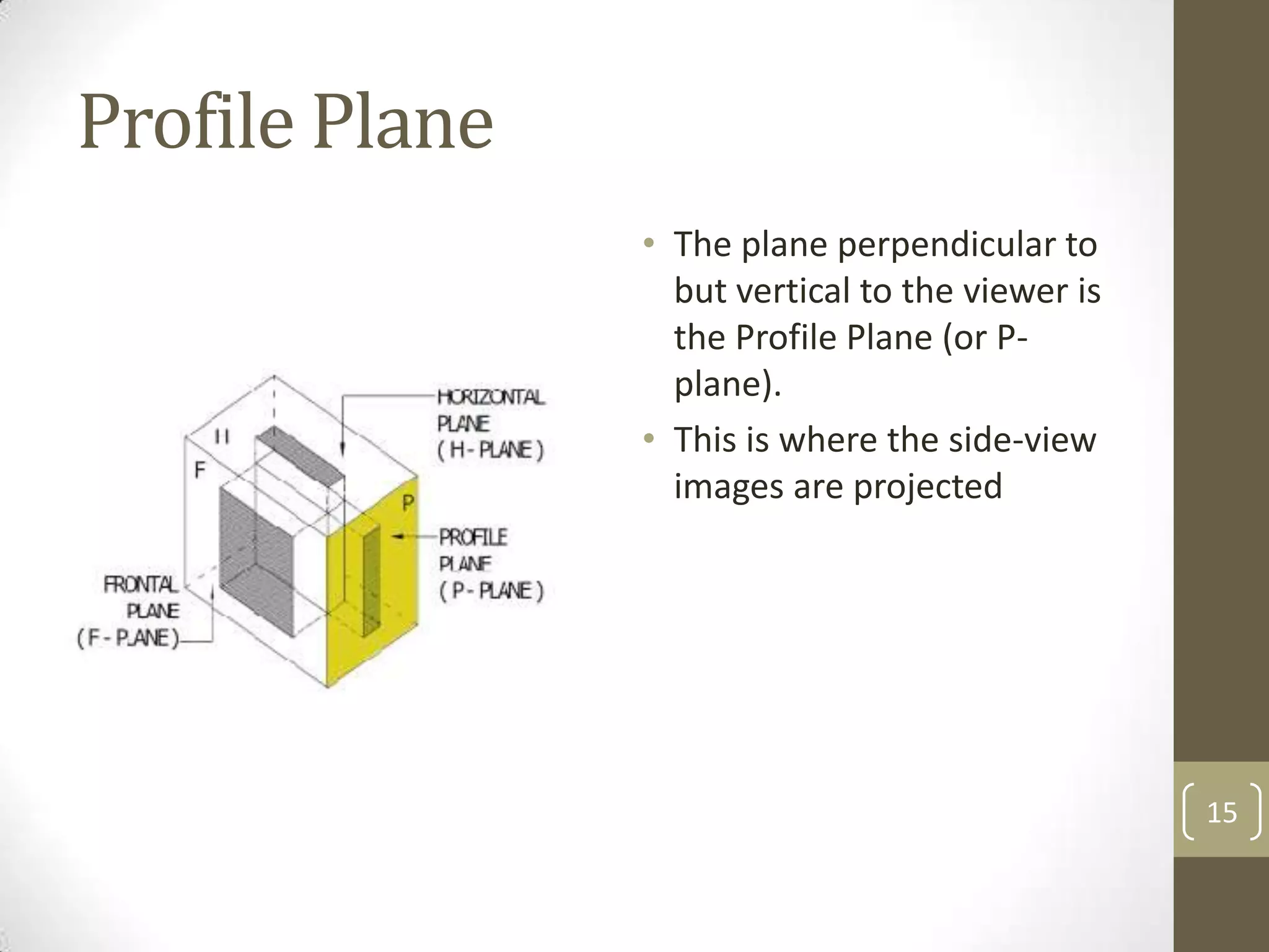
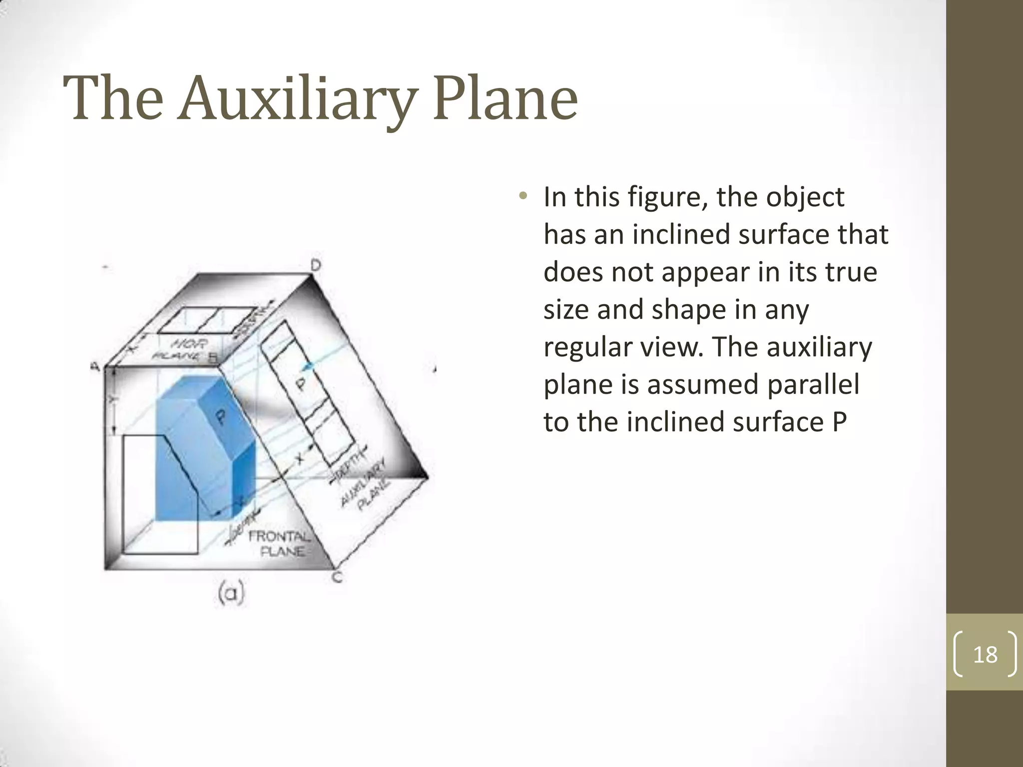
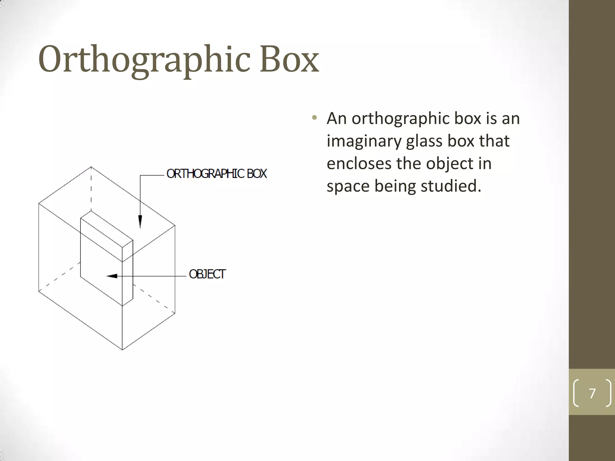
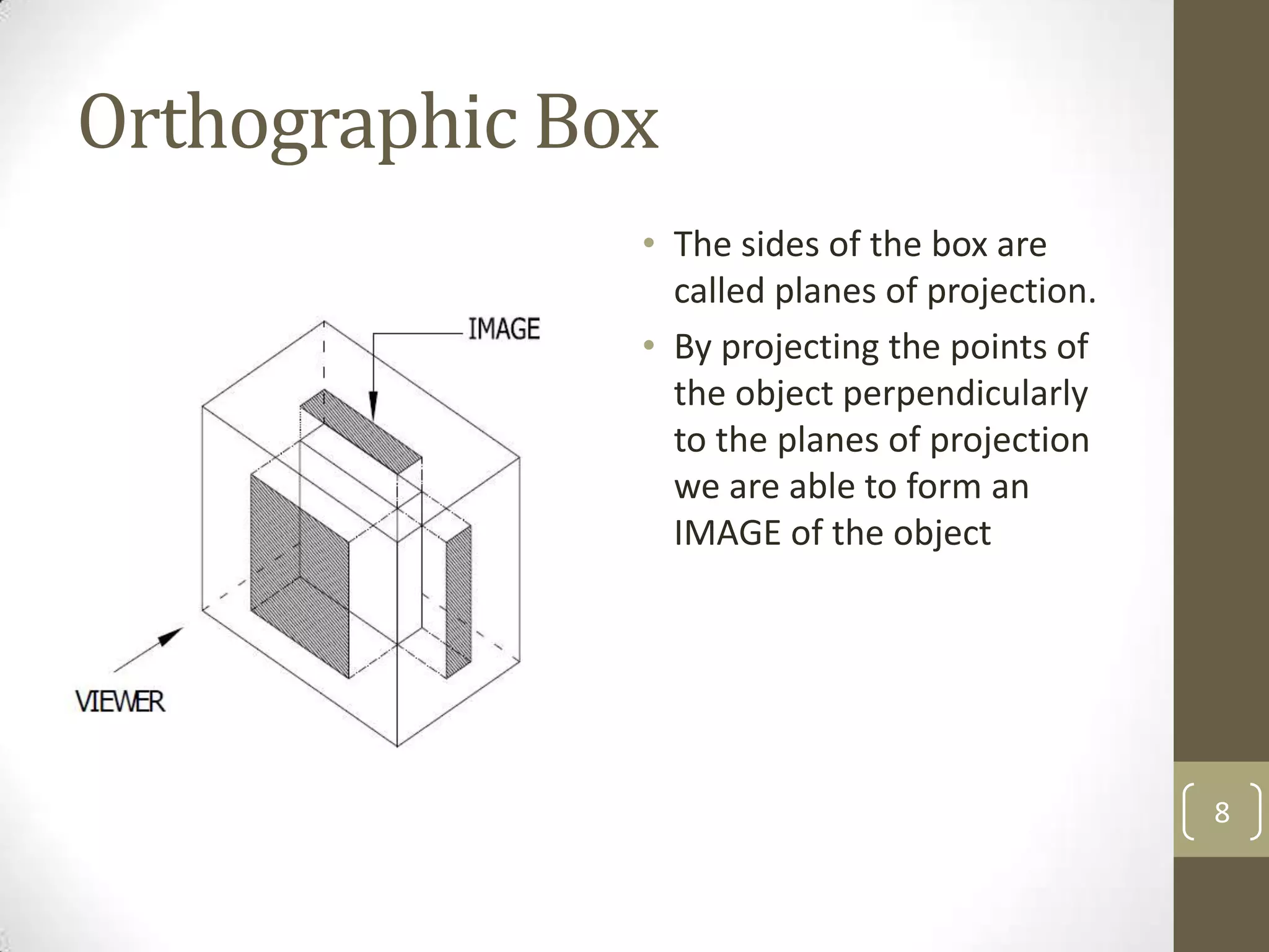
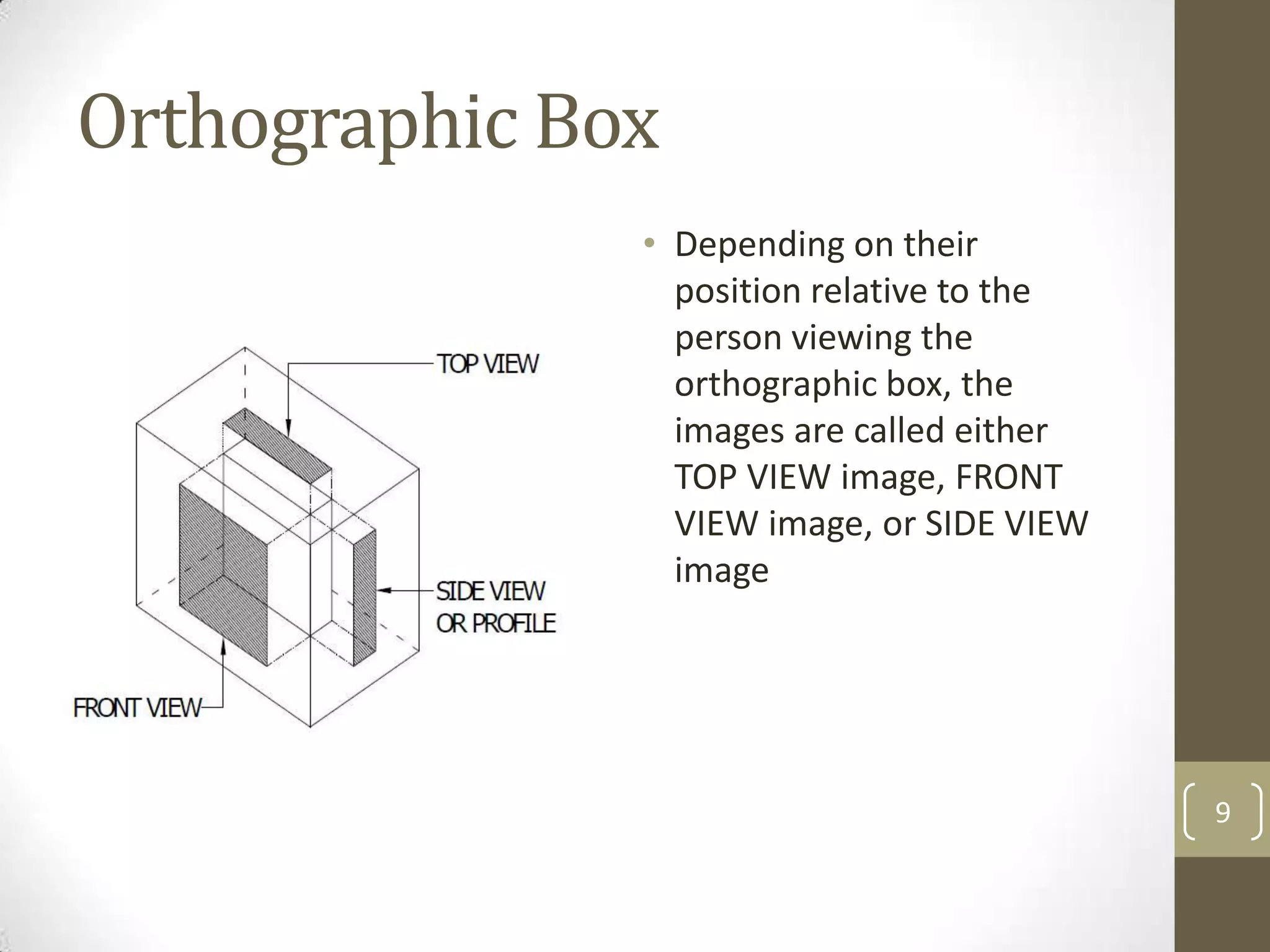
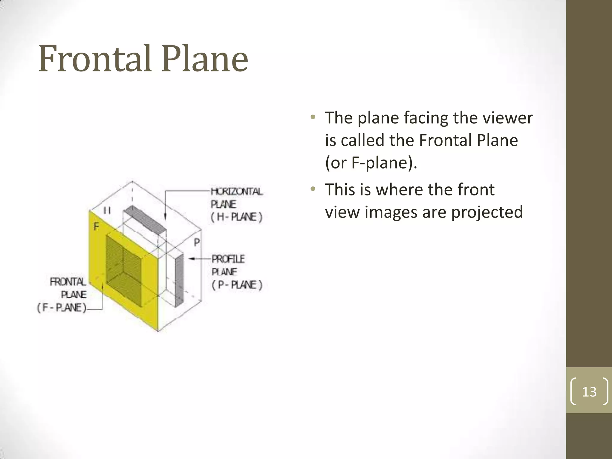
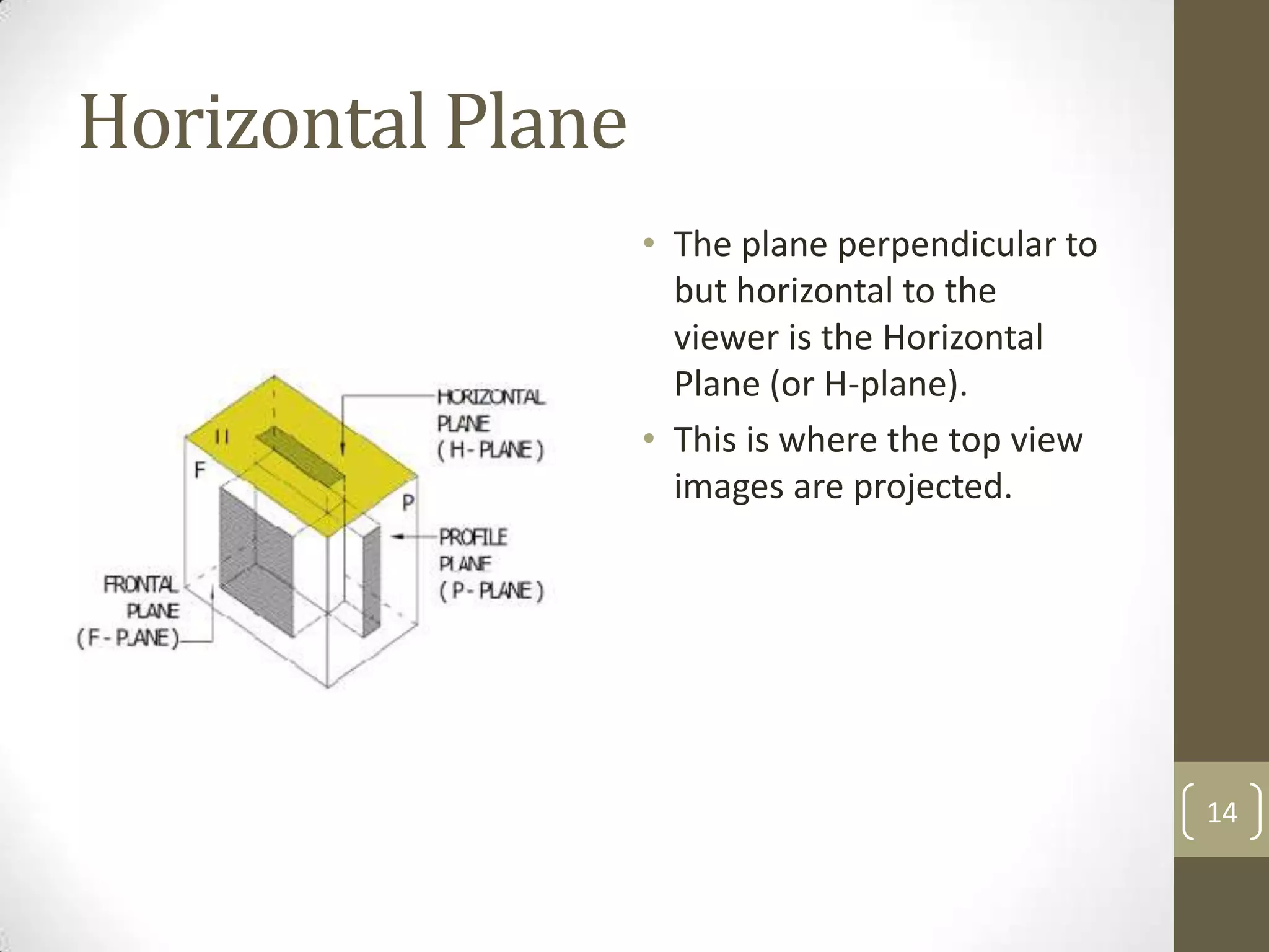
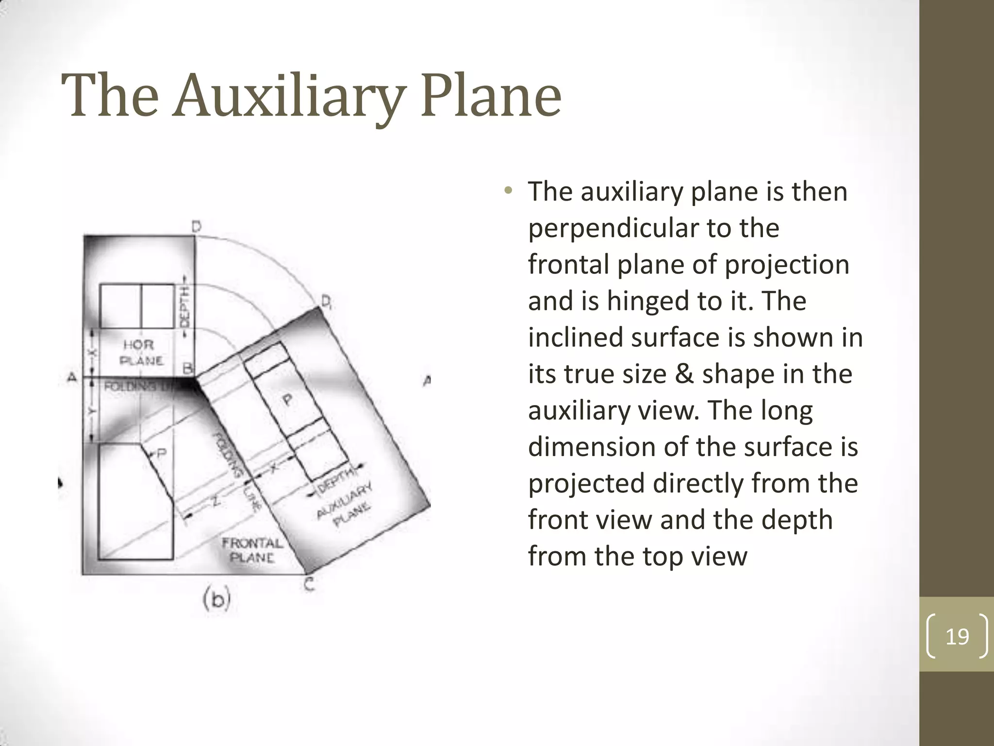
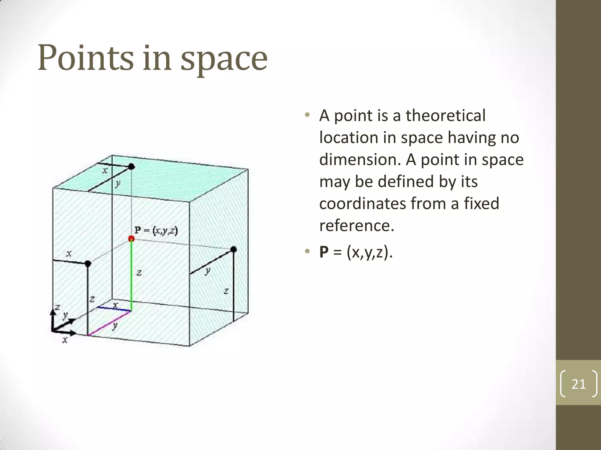
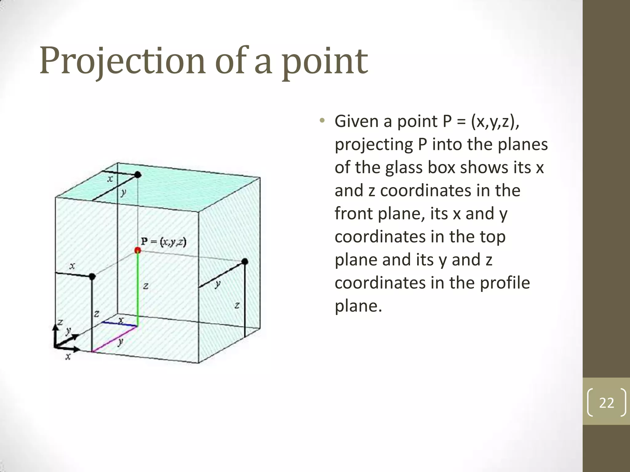
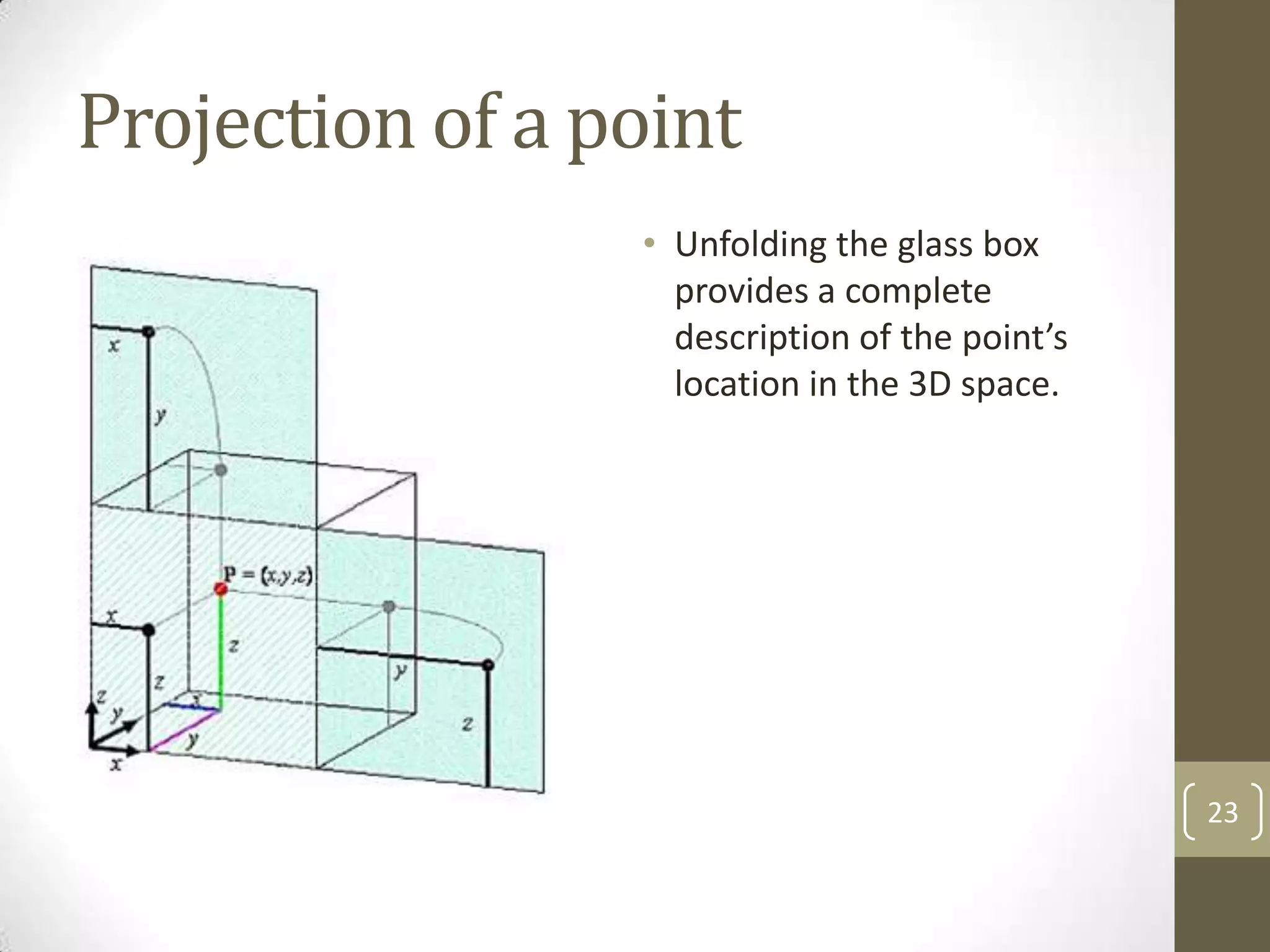
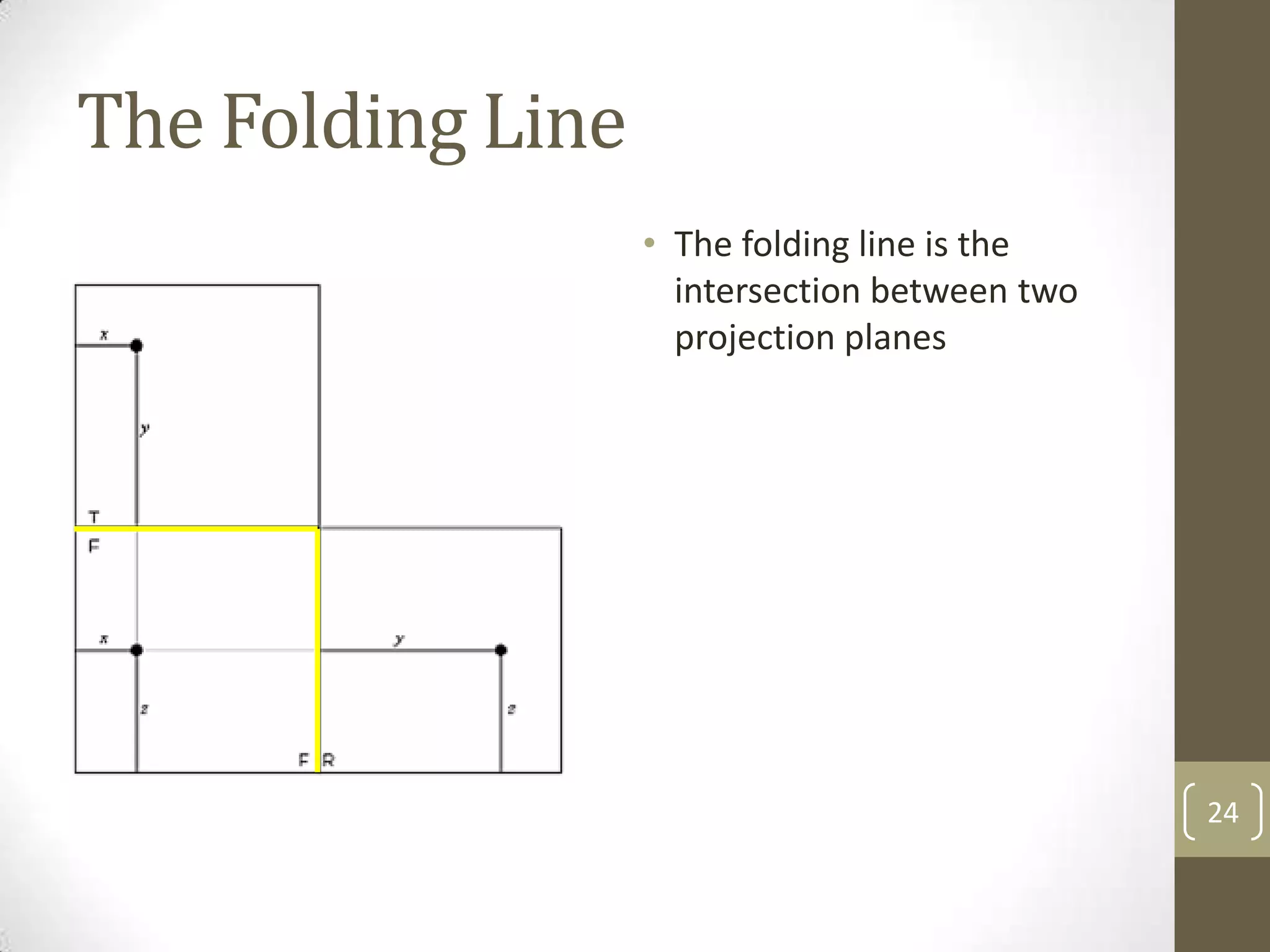
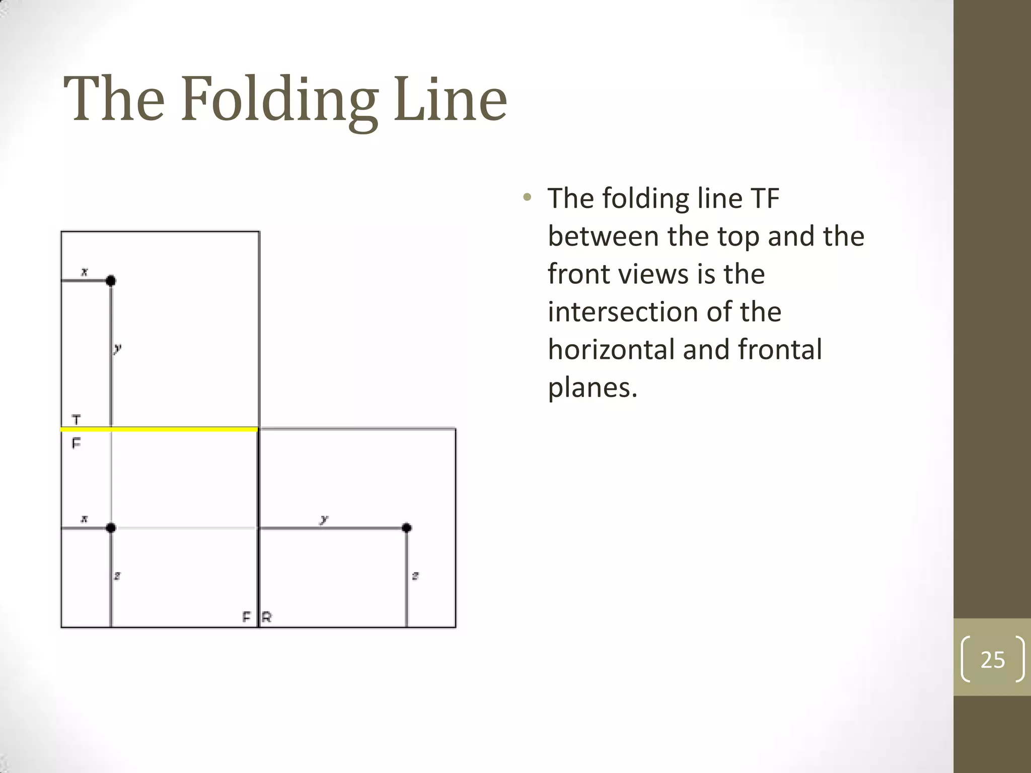
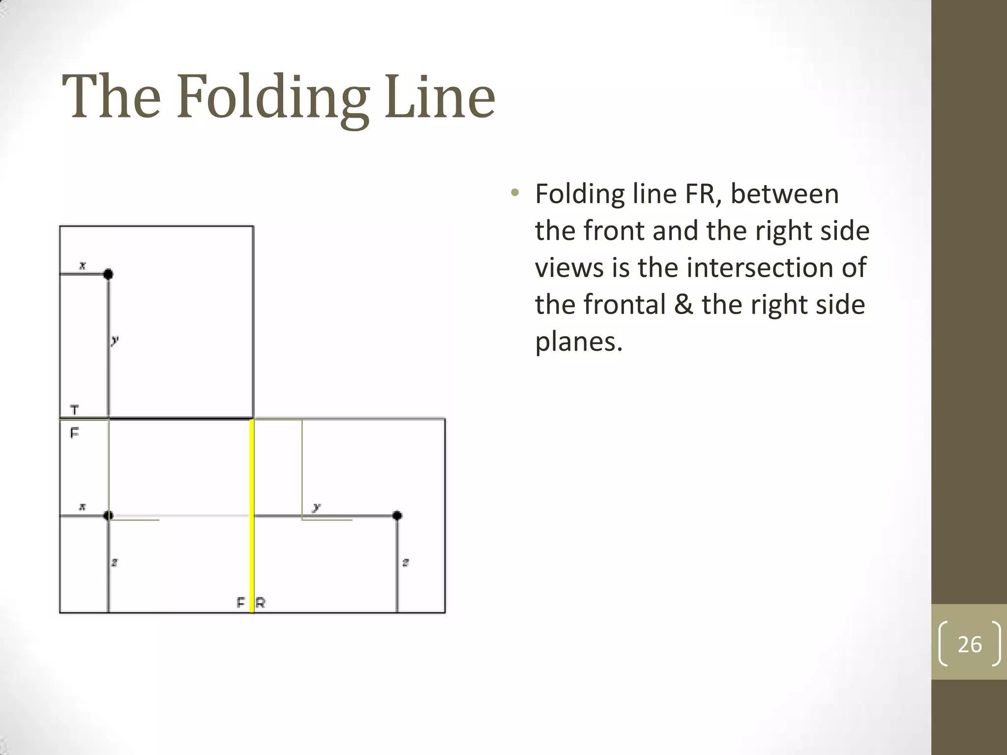
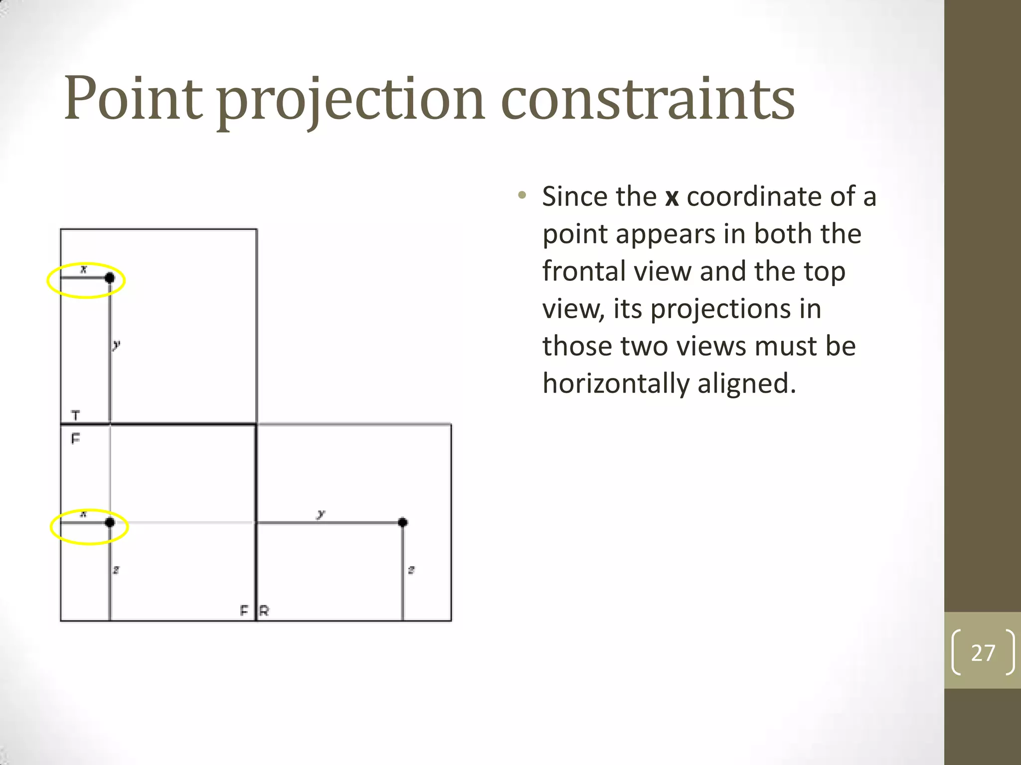
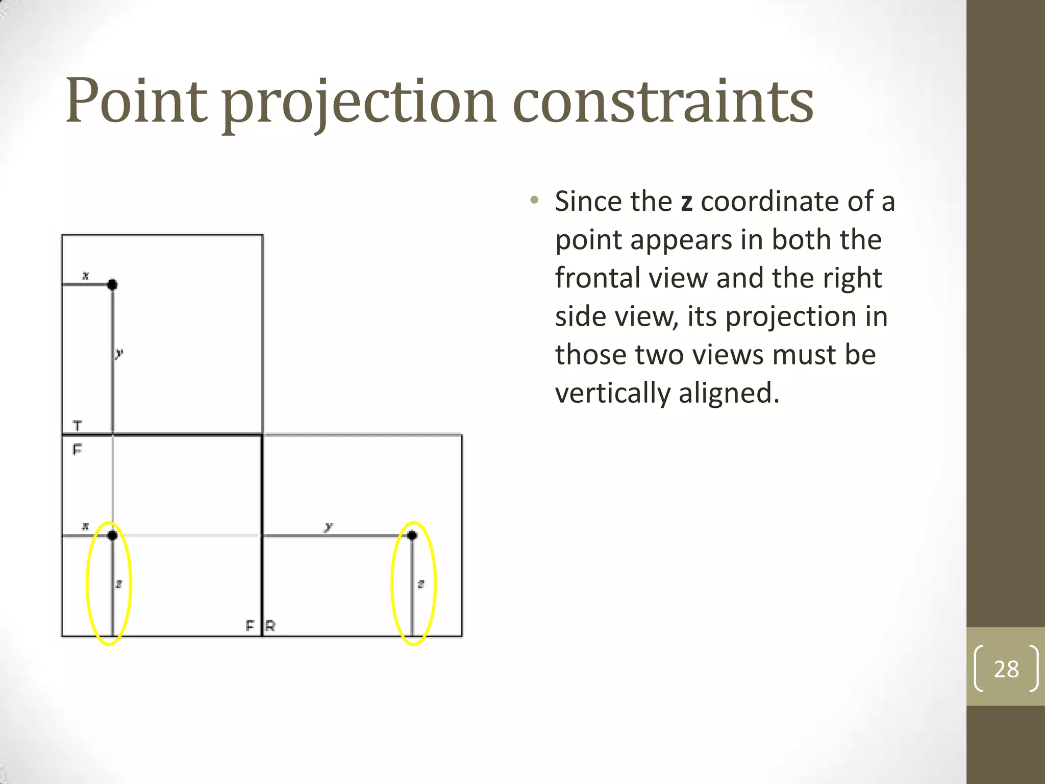
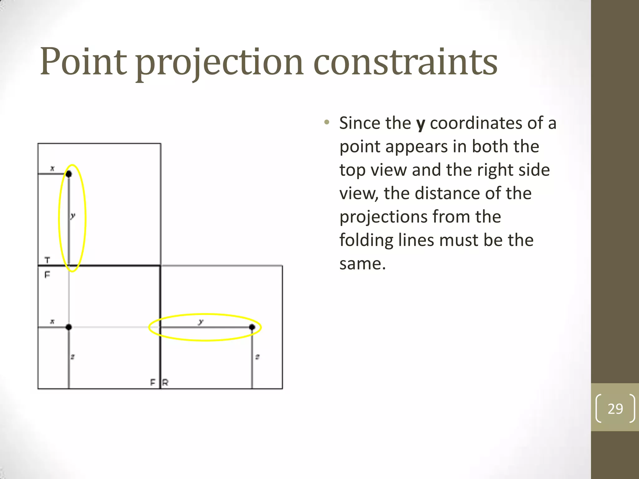
Descriptive
Geometry
ARCHT. TROY ELIZAGA


                      1
Descriptive Geometry
• Descriptive geometry the branch of geometry which allows
  the representation of three-dimensional objects in two
  dimensions, by using a specific set of procedures.


                                                             2
Descriptive Geometry
               • Gaspard Monge is usually
                 considered the "father of
                 descriptive geometry".
               • He first developed his
                 techniques to solve
                 geometric problems in
                 1765 while working as a
                 draftsman for military
                 fortifications, and later
                 published his findings


                                             3
ORTHOGRAPHIC PROJECTION   4
Orthographic Projection
• Orthographic projection (or orthogonal projection) is a
  means of representing a three-dimensional object in two
  dimensions.
• It is a form of parallel projection, where all the projection lines
  are orthogonal to the projection plane.


                                                                        5
Orthographic Box
• Space is defined as the infinite extension of the three
  dimensional region in which all matter exists.
• In order to study an object in space, it is necessary to
  “enclose” the object so that we can make use of the enclosure
  as a reference point.
• This is done with the use of the orthographic box.


                                                                  6
Orthographic Box
               • An orthographic box is an
                 imaginary glass box that
                 encloses the object in
                 space being studied.


                                             7
Orthographic Box
               • The sides of the box are
                 called planes of projection.
               • By projecting the points of
                 the object perpendicularly
                 to the planes of projection
                 we are able to form an
                 IMAGE of the object


                                                8
Orthographic Box
               • Depending on their
                 position relative to the
                 person viewing the
                 orthographic box, the
                 images are called either
                 TOP VIEW image, FRONT
                 VIEW image, or SIDE VIEW
                 image


                                            9
PLANES OF PROJECTION   10
Planes of Projection
• There are two main types of planes of projection
  • Principal planes of projection
  • Auxiliary planes of projection


                                                     11
Principal Planes of Projections
• Principal planes of projection are the main “faces” of the
  orthographic box.
• They are labelled depending on their relative position to the
  viewer.
• There are basically three principal planes of projections:
  • Frontal Plane
  • Horizontal Plane
  • Profile Plane


                                                                  12
Frontal Plane
                • The plane facing the viewer
                  is called the Frontal Plane
                  (or F-plane).
                • This is where the front
                  view images are projected


                                                13
Horizontal Plane
                   • The plane perpendicular to
                     but horizontal to the
                     viewer is the Horizontal
                     Plane (or H-plane).
                   • This is where the top view
                     images are projected.


                                                  14
Profile Plane
                • The plane perpendicular to
                  but vertical to the viewer is
                  the Profile Plane (or P-
                  plane).
                • This is where the side-view
                  images are projected


                                                  15
Alternatives
• It is also possible to project an image backwards, to the left,
  and downwards to get the rear view, left side view, and the
  bottom view respectively.
• In most problems, however, we normally consider its two
  dimensional images in at least two views.
• Usually the top view and front view images will suffice.
• Following the American system for technical drawings, the
  right side view may be used when a side view is necessary.


                                                                    16
Auxiliary Plane of Projection
• The auxiliary planes of projections are any planes which are
  neither parallel to nor perpendicular to the viewer.
• Their orientation is arbitrary.
• Their labels are also arbitrary, i.e. they may use any letters
  other than the letters used to label the principal planes of
  projections


                                                                   17
The Auxiliary Plane
                • In this figure, the object
                  has an inclined surface that
                  does not appear in its true
                  size and shape in any
                  regular view. The auxiliary
                  plane is assumed parallel
                  to the inclined surface P


                                                 18
The Auxiliary Plane
                • The auxiliary plane is then
                  perpendicular to the
                  frontal plane of projection
                  and is hinged to it. The
                  inclined surface is shown in
                  its true size & shape in the
                  auxiliary view. The long
                  dimension of the surface is
                  projected directly from the
                  front view and the depth
                  from the top view

                                                 19
PROJECTING POINTS   20
Points in space
                  • A point is a theoretical
                    location in space having no
                    dimension. A point in space
                    may be defined by its
                    coordinates from a fixed
                    reference.
                  • P = (x,y,z).


                                                  21
Projection of a point
                 • Given a point P = (x,y,z),
                   projecting P into the planes
                   of the glass box shows its x
                   and z coordinates in the
                   front plane, its x and y
                   coordinates in the top
                   plane and its y and z
                   coordinates in the profile
                   plane.


                                                  22
Projection of a point
                 • Unfolding the glass box
                   provides a complete
                   description of the point’s
                   location in the 3D space.


                                                23
The Folding Line
                   • The folding line is the
                     intersection between two
                     projection planes


                                                24
The Folding Line
                   • The folding line TF
                     between the top and the
                     front views is the
                     intersection of the
                     horizontal and frontal
                     planes.


                                               25
The Folding Line
                   • Folding line FR, between
                     the front and the right side
                     views is the intersection of
                     the frontal & the right side
                     planes.


                                                    26
Point projection constraints
                 • Since the x coordinate of a
                   point appears in both the
                   frontal view and the top
                   view, its projections in
                   those two views must be
                   horizontally aligned.


                                                 27
Point projection constraints
                 • Since the z coordinate of a
                   point appears in both the
                   frontal view and the right
                   side view, its projection in
                   those two views must be
                   vertically aligned.


                                                  28
Point projection constraints
                 • Since the y coordinates of a
                   point appears in both the
                   top view and the right side
                   view, the distance of the
                   projections from the
                   folding lines must be the
                   same.


                                                  29
Rule 1: The alignment rule
                • The projections of a point
                  in two consecutive views
                  are aligned with respect to
                  the normal to the folding
                  line.


                                                30

Descgeom 01 orthographic projection

  • 1.
  • 2.
    Descriptive Geometry • Descriptivegeometry the branch of geometry which allows the representation of three-dimensional objects in two dimensions, by using a specific set of procedures. 2
  • 3.
    Descriptive Geometry • Gaspard Monge is usually considered the "father of descriptive geometry". • He first developed his techniques to solve geometric problems in 1765 while working as a draftsman for military fortifications, and later published his findings 3
  • 4.
  • 5.
    Orthographic Projection • Orthographicprojection (or orthogonal projection) is a means of representing a three-dimensional object in two dimensions. • It is a form of parallel projection, where all the projection lines are orthogonal to the projection plane. 5
  • 6.
    Orthographic Box • Spaceis defined as the infinite extension of the three dimensional region in which all matter exists. • In order to study an object in space, it is necessary to “enclose” the object so that we can make use of the enclosure as a reference point. • This is done with the use of the orthographic box. 6
  • 7.
    Orthographic Box • An orthographic box is an imaginary glass box that encloses the object in space being studied. 7
  • 8.
    Orthographic Box • The sides of the box are called planes of projection. • By projecting the points of the object perpendicularly to the planes of projection we are able to form an IMAGE of the object 8
  • 9.
    Orthographic Box • Depending on their position relative to the person viewing the orthographic box, the images are called either TOP VIEW image, FRONT VIEW image, or SIDE VIEW image 9
  • 10.
  • 11.
    Planes of Projection •There are two main types of planes of projection • Principal planes of projection • Auxiliary planes of projection 11
  • 12.
    Principal Planes ofProjections • Principal planes of projection are the main “faces” of the orthographic box. • They are labelled depending on their relative position to the viewer. • There are basically three principal planes of projections: • Frontal Plane • Horizontal Plane • Profile Plane 12
  • 13.
    Frontal Plane • The plane facing the viewer is called the Frontal Plane (or F-plane). • This is where the front view images are projected 13
  • 14.
    Horizontal Plane • The plane perpendicular to but horizontal to the viewer is the Horizontal Plane (or H-plane). • This is where the top view images are projected. 14
  • 15.
    Profile Plane • The plane perpendicular to but vertical to the viewer is the Profile Plane (or P- plane). • This is where the side-view images are projected 15
  • 16.
    Alternatives • It isalso possible to project an image backwards, to the left, and downwards to get the rear view, left side view, and the bottom view respectively. • In most problems, however, we normally consider its two dimensional images in at least two views. • Usually the top view and front view images will suffice. • Following the American system for technical drawings, the right side view may be used when a side view is necessary. 16
  • 17.
    Auxiliary Plane ofProjection • The auxiliary planes of projections are any planes which are neither parallel to nor perpendicular to the viewer. • Their orientation is arbitrary. • Their labels are also arbitrary, i.e. they may use any letters other than the letters used to label the principal planes of projections 17
  • 18.
    The Auxiliary Plane • In this figure, the object has an inclined surface that does not appear in its true size and shape in any regular view. The auxiliary plane is assumed parallel to the inclined surface P 18
  • 19.
    The Auxiliary Plane • The auxiliary plane is then perpendicular to the frontal plane of projection and is hinged to it. The inclined surface is shown in its true size & shape in the auxiliary view. The long dimension of the surface is projected directly from the front view and the depth from the top view 19
  • 20.
  • 21.
    Points in space • A point is a theoretical location in space having no dimension. A point in space may be defined by its coordinates from a fixed reference. • P = (x,y,z). 21
  • 22.
    Projection of apoint • Given a point P = (x,y,z), projecting P into the planes of the glass box shows its x and z coordinates in the front plane, its x and y coordinates in the top plane and its y and z coordinates in the profile plane. 22
  • 23.
    Projection of apoint • Unfolding the glass box provides a complete description of the point’s location in the 3D space. 23
  • 24.
    The Folding Line • The folding line is the intersection between two projection planes 24
  • 25.
    The Folding Line • The folding line TF between the top and the front views is the intersection of the horizontal and frontal planes. 25
  • 26.
    The Folding Line • Folding line FR, between the front and the right side views is the intersection of the frontal & the right side planes. 26
  • 27.
    Point projection constraints • Since the x coordinate of a point appears in both the frontal view and the top view, its projections in those two views must be horizontally aligned. 27
  • 28.
    Point projection constraints • Since the z coordinate of a point appears in both the frontal view and the right side view, its projection in those two views must be vertically aligned. 28
  • 29.
    Point projection constraints • Since the y coordinates of a point appears in both the top view and the right side view, the distance of the projections from the folding lines must be the same. 29
  • 30.
    Rule 1: Thealignment rule • The projections of a point in two consecutive views are aligned with respect to the normal to the folding line. 30