
Recommended
More Related Content
What's hot
What's hot (20)
Similar to Decision directed carrier signal
Similar to Decision directed carrier signal (20)
Recently uploaded
Recently uploaded (20)
Decision directed carrier signal
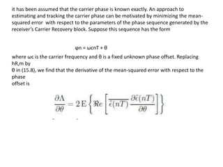
- 1. it has been assumed that the carrier phase is known exactly. An approach to estimating and tracking the carrier phase can be motivated by minimizing the mean- squared error with respect to the parameters of the phase sequence generated by the receiver’s Carrier Recovery block. Suppose this sequence has the form ϕn = ωcnT + θ where ωc is the carrier frequency and θ is a fixed unknown phase offset. Replacing hR,m by θ in (15.8), we find that the derivative of the mean-squared error with respect to the phase offset is
- 2. Remember that the baseband error is (nT) = cn−nd− ˜σ(nT) = cn−nd−σ+(nT)e−j(ωcnT+θ) Therefore, On replacing ˜(nT) by cn−nd − ˜σ(nT), the following alternative formula for the derivative is obtained: This derivative has an interesting physical interpretation. Let cn−nd = Rcejβc and ˜σ(nT) = Rσejβσ
- 3. Let be the polar form representations for these two complex numbers. Remember that the equalized baseband output sample ˜σ(nT) is supposed to be a close approximation to the ideal symbol cn−nd . Then m[ cn−nd ˜σ(nT)] = RcRσ sin(βσ − βc) so
- 4. This has the same sign as the phase error between the ideal constellation point cn−nd and the equalized baseband received point ˜σ(nT) if the phase error is not too large, and is nearly a linear function of the error for small phase errors. This phase error measure can be used in a phase-locked loop to iteratively adjust θ so the baseband equalized points are aligned in angle with the ideal constellation points. Changing θ by some angle has the effect of rotating the baseband equalized points by the negative of the angle.
- 5. can be replaced by Rc in (15.48 ). These observations suggest adjusting θ according to the formula where k1 is a small positive constant. A practical realization for a second-order carrier tracking loop based on this equation and including carrier frequency offset tracking is shown in Figure 15.4. First, an approximation to the phase error is computed from the baseband equalizer output sample ˜σ(nT) by the formula During initial startup, a known symbol sequence is often transmitted and the Ideal Reference Generator in the receiver replicates these symbols. After the equalizer and carrier tracking loop have converged, the outputs of the Slicer are substituted for the known sequence and the system operates in the decision directed mode. The phase estimate generated by the lower part of the block diagram is ϕn+1 = ˆϕn + ωcT + k1Δθ(n) + ψ(n) where ψ(n) = ψ(n − 1) + k2Δθ(n)
- 6. Notice that ωcT is the nominal change in the carrier phase angle between symbols. When Δθ(n) is zero for all n and the z−1 delay elements are initially cleared, the phase generated is The philosophy behind the carrier tracking loop is to increment the phase angle predicted for the next symbol instant, ˆ ϕn + ωcT, by a small fraction, k1, of the current phase error estimate Δθ(n). In addition, a fraction, k2, of the phase error is accumulated to measure any bias caused by a frequency offset, and added to the phase increment. The system is a second order phase-locked loop similar in behaviour to the ones discussed in previous chapters. It will track a constant phase and frequency offset with zero final error. The ratio k1/k2 should be in the order of 100 for good transient response.