Call Girls Service Nagpur Tanvi Call 7001035870 Meet With Nagpur Escorts
M4.pdf
1. Module 4: Baseband System
When digital data are transmitted through a band limited channel, dispersion in the channel
causes an overlap in time between successive symbols. This form of distortion, known as
inter symbol interference (ISI), can pose a serious problem to the quality of reception of it is
left uncontrolled. This ISI can be controlled by the use of perfect receiver with the techniques
based on shaping baseband response of the system. As such, they are applicable to baseband
data transmission system using coaxial cables or optical fiber waveguides.
4.1 Inter Symbol Interference:
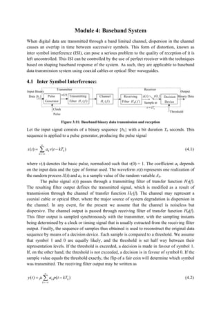
Figure 3.11: Baseband binary data transmission and reception
Let the input signal consists of a binary sequence {bk} with a bit duration Tb seconds. This
sequence is applied to a pulse generator, producing the pulse signal
( ) ( )
k b
k
x t a v t kT
(4.1)
where v(t) denotes the basic pulse, normalized such that v(0) = 1. The coefficient ak depends
on the input data and the type of format used. The waveform x(t) represents one realization of
the random process X(t) and ak is a sample value of the random variable Ak.
The pulse signal x(t) passes through a transmitting filter of transfer function HT(f).
The resulting filter output defines the transmitted signal, which is modified as a result of
transmission through the channel of transfer function HC(f). The channel may represent a
coaxial cable or optical fiber, where the major source of system degradation is dispersion in
the channel. In any event, for the present we assume that the channel is noiseless but
dispersive. The channel output is passed through receiving filter of transfer function HR(f).
This filter output is sampled synchronously with the transmitter, with the sampling instants
being determined by a clock or timing signal that is usually extracted from the receiving filter
output. Finally, the sequence of samples thus obtained is used to reconstruct the original data
sequence by means of a decision device. Each sample is compared to a threshold. We assume
that symbol 1 and 0 are equally likely, and the threshold is set half way between their
representation levels. If the threshold is exceeded, a decision is made in favour of symbol 1.
If, on the other hand, the threshold is not exceeded, a decision is in favour of symbol 0. If the
sample value equals the threshold exactly, the flip of a fair coin will determine which symbol
was transmitted. The receiving filter output may be written as
( ) ( )
k b
k
y t a p t kT
(4.2)
Clock
Pulse
Sample at
= b
t iT
Pulse
Generator
( )
x t Transmitting
Filter ( )
T
H f
Channel
( )
C
H f
Receiving
Filter ( )
R
H f
Decision
Device
( )
y t ( )
i
y t
Threshold
Output
Binary Data
Input Binary
Data { }
k
b
Transmitter Receiver
2. where µ is a scaling factor and the pulse p(t) is normalized such that p(0) = 1.
The output y(t) is produced in response to the binary data waveform applied to the
input of the transmitting filter. Specifically, the pulse µp(t) is the response of the cascade
connection of the transmitting filter, the channel, and the receiving filter, which is produced
by the pulse v(t) applied to the input of this cascade connection. Therefore, we may relate p(t)
to v(t) in the frequency domain as
( ) ( ) ( ) ( ) ( )
T C R
P f V f H f H f H f
(4.3)
where P(f) and V(f) are the Fourier transforms of p(t) and v(t), respectively. Note that the
normalization of p(t) as in Eq. (4.2) means that the total area under the curve P(f) equals
unity.
The receiving filter output y(t) is sampled at time ti = iTb (with i taking on integer
values), yielding
( ) ( )
i k b b
k
y t a p iT kT
( )
i k b b
k
k i
a a p iT kT
(4.4)
In Eq. (4.4), the first term µai is produced by the ith
transmitted bit. The second term
represents the residual effect of all other transmitted bits on the decoding of the ith
bit; this
residual effect is called inter symbol interference (ISI).
In physical terms, ISI arises because of imperfections in the overall frequency
response of the system. When a short pulse of duration Tb seconds is transmitted through a
band limited system, the frequency components constituting the input pulse ate differentially
attenuated and, more significantly, differentially delayed by the system. Consequently, the
pulse appearing at the output of the system is dispersed over an interval longer than Tb
seconds. Thus, when a sequence of short pulses (representing binary 1s and 0s) are
transmitted through the system, one pulse every Tb seconds, the dispersed responses
originating from different symbol intervals will interfere with each other, thereby resulting in
inter symbol interference.
In the absense of ISI, we observe from Eq. (4.4) that y(ti) = µai, which shows that,
under these conditions, the ith transmitted bit can be decoded correctly. The presense of ISI
in the system, however, introduces errors in the decision devise at the receiver output.
Therefore, in the design of the transmitting and receiving filters, the objective is to minimize
the effects of ISI, and thereby deliver the digital data to its destination with the smallest error
rate possible.
A band limited. channel used for base band signal transmission is typically view as
low pass filter as shown in Figure (a). Due to dispersive nature of wired channel, each pulse
may get interferennce from most of the previous pulses as shown in Figure (b). This
interference is usually called as inter symbol interference (ISI)
3. Figure (a)
Figure (b)
Nyquist’s Criterion for Distortion less Baseband Binary Transmission:
Typically, the transfer function of the channel and the transmitted pulse shape are specified,
and the problem is to determine the transfer functions of the transmitting and receiving filters
so as to reconstruct the transmitted data sequence {bk}. The receiver does this by extracting
and then decoding the corresponding sequence of weights, {ak}, from the output y(t). Except
for a scaling factor, y(t) is determined by the ak and the received pulse p(t); as we see from
Eq. (4.1). The extraction involves sampling the output y(t) at some time t = iTb. The decoding
requires that the weighted pulse contribution ak p(iTb – kTb) for k = 1 be free from ISI due to
the over sampling tails of all other weighted pulse contributions represented by k ≠ i. This is,
in turn, requires that we control the received pulse p(t), as shown by:
4. 1,
( )
0,
b b
i k
p iT kT
i k
(4.5)
where, by normalization, p(0) = 1. If p(t) satisfies the condition of Eq. (4.5), the receiver
output, given by Eq. (4.4), simplifies to:
( )
i i
y t a
which implies zero inter symbol interference. Hence, the condition of Eq. (4.5) assures
perfect reception in the absence of noise. Form the design point of view, it is informative to
transform the condition of Eq. (4.5) into the frequency domain. Consider then the sequence of
samples {p(nTb)}, where n = 0, ±1, ±2,…From the sampling process for a low-pass function,
we recall that sampling in the time domain produces periodicity in the frequency domain. In
particular, we may write:
( ) ( )
b b
n
P f R P f nR
(4.6)
where Rb = 1/Tb is the bit rate, Pδ(f) is the Fourier transform of an infinite periodic sequence
of delta functions of period Tb, and whose strengths are weighted by the respective sample
values of p(t). That is, Pδ(f) is given by:
( ) ( ) ( ) exp( 2 )
b b
m
P f p mT t mT j ft dt
(4.7)
Let the integer m = i – k. The i = k corresponds to m = 0. And likewise i ≠ k corresponds to m
≠ 0. Accordingly, imposing the condition of Eq. (4.5) on sample values of p(t) in the integral
of Eq. (4.7), we get:
( ) (0) ( )exp( 2 ) (0)
P f p t j ft dt p
(4.8)
where we have made use of the sifting property of the delta function. Since p(0) = 1, by
normalization, we thus see from Eq. (4.6) and Eq. (4.8) that the condition for zero inter
symbol interference is satisfied if:
( )
b b
n
P f nR T
(6.27)
Eq. (4.5) formulated in terms of the time function p(t), or equivalently, Eq. (4.9) formulated
in terms of the corresponding frequency function P(f), constitutes the Nyquist criterion for
distortion for distortion less base band transmission in the absence of noise. It provides a
method for constructing band-limited functions to overcome the effects of inter symbol
interference. The method depends on sampling the received signal at midpoints of the
signalling intervals.
5. Ideal Solution:
(a)
(b)
Figure 6.6: (a) Spectrum of ideal pulse p(t) (b) Ideal pulse p(t)
Figure 6.6 (a) and Figure 6.6 (b) show spectrum of ideal pulse and ideal pulse respectively.
The ideal pulse is obtained by applying IFT to the spectrum shown in Figure 6.6 (a) as
follows:
2
( ) ( ) j ft
p t P f e df
/2
2
/2
1
b
b
R
j ft
b
R
e df
R
/2
2
/2
1
2
b
b
f R
j ft
f R
b
e
j tR
1
2
b b
j tR j tR
b
e e
tR j
sin( )
b
b
tR
tR
sinc( ) sinc(2 )
b o
tR B t
2
b
R
2
b
R
( )
P f
f
b
T
6. For the spectrum of ideal pulse shown in Figure 6.6(a), the frequency domain Nyquist
criterion given in eq. (6.27) is satisfied as shown in Figure 6.6 (c).
Figure 6.6(c)
7. Practical Solution:
Instead of the spectrum of the ideal pulse shown in Figure 6.6(a), let us consider a spectrum
raised cosine pulse shown in Figure 6.6 (d):
Figure 6.6 (d)
8. Then, for the spectrum of raised cosine pulse shown in Figure 6.6 (d), the frequency domain
Nyquist criterion given in eq. (6.27) is satisfied as shown in Figure 6.6 (e).
Figure 6.6 (e)
10. (b)
Figure 6.7: Response for different roll off factor: (a) Frequency response (b) Time response. Note that
Bo=1/2Tb.
3.2 EYE Pattern
One way to study ISI in a data transmission system experimentally is to apply the received
wave to the vertical deflection plates of an oscilloscope and to apply a saw tooth wave at the
transmitted symbol rate R = 1/T to the horizontal deflection plates. The waveform in the
successive symbol intervals are thereby translated into one interval on the oscilloscope
display. The resulting display is called as an eye pattern because of its resemblance to the
human eye for the binary waves. The interior region of the eye pattern is called the eye
opening. Any eye diagram provides a great deal of information about the performance of the
pertinent system, as described next:
1. The width of the eye diagram defines the time interval over which the received wave
can be sampled without error from inter symbol interference. It is apparent that the
preferred time for sampling is the instant of time at which the eye is open widest.
2. The sensitivity of the system to timing error is determined by the rate of closure of the
eye as the sampling time is varied.
3. The height of the eye opening, at a specified sampling time, defines the margin over
noise.
When the effect of inter symbol interference is severe, traces from the upper portion
of the eye pattern cross traces from the lower portion, with the result that the eye is
completely closed. In such a situation, it is impossible to avoid error due to the combined
11. presence of inter symbol interference and noise in the system, and a solution has to be found
to correct for them.
Figure 3.12: Interpretation of eye pattern
12. Fig.4.6.1 (a) Binary sequence transmitted (b) Received signal by baseband transmission system (c)
Eye pattern of signal in (b) (d) Eye pattern for large number of bits in waveform y(t)