Enzyme, Pharmaceutical Aids, Miscellaneous Last Part of Chapter no 5th.pdf
1 bode plot
1. 1 Bode Plot
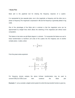
Bode plot is the graphical tool for drawing the frequency response of a system.
It is represented by two separate plots, one is the magnitude vs frequency and the other one is
phase vs frequency.The magnitude is expressed in dB and the frequency is generally plotted in log
scale.
One of the advantages of the Bode plot in s-domain is that the magnitude curve can be
approximated by straight lines which allows the sketching of the magnitude plot without exact
computation.
This feature is lost when we plot Bode diagram in z-domain . To incorporate this feature we use bi-
linear transformation to transform unit circle of the z-plane into the imaginary axis of another
complex plane, w plane, where
From the power series expansion
For frequency domain analysis the above bi-linear transformation may be used to
convert GH(z) to GH(w) and then construct the Bode plot.
Example 1: Let us consider a digital control system for which the loop transfer function is given by
2. where sampling time T = 0.1 sec. Putting , we get the transfer function in w plane
as
where is the frequency in w plane. Corner frequencies are 1/1.0026 = 0.997 rad/sec and
1/0.05 = 20 rad/sec.
The straight line asymptotes of the Bode plot can be drawn using the following.
• • Up to ωw= 0.997 rad/sec, the magnitude plot is a straight line with slope -
20dB/decade.At ωw= 0.01 rad/sec,the magnitude
is dB.
• From ωw= 0.997 rad/sec to ωw= 20 rad/sec, the magnitude plot is a straight line with slope - 20 -
20 = - 40 dB/decade.
• Since both of the zeros will contribute same to the magnitude plot, after ωw= 20 rad/sec, the slope
of the straight line will be - 40 + 20 + 20 = 0 dB/decade.
The asymptotic magnitude plot is shown in Figure 1.
3. Figure 1: Bode asymptotic magnitude plot for Example 1
One should remember that the actual plot will be slightly different from the asymptotic plot. In the
actual plot, errors due to straight line assumptions is compensated.
Phase plot is drawn by varying the frequency from 0.01 to 100 rad/sec at regular intervals. The
phase angle contributed by one zero will be canceled by the other. Thus the phase will vary from
- 90° (270°) to - 180° (180°).
Figure 2 shows the actual magnitude and phase plot as drawn in MATLAB.
4. Figure 2: Bode magnitude and phase plot for Example 1
1.1 Gain margin and Phase margin
Gain margin and phase margins are the measures of relative stability of a system.
Similar to continuous time case, we have to first define phase and gain cross over frequencies
before defining gain margin and phase margin.
Gain margin is the safety factor by which the open loop gain of a system can be increased before
the system becomes unstable. It is measured as
5. where ωp is the phase crossover frequency which is defined as the frequency where the phase of
the loop transfer function is 180°.
Similarly Phase margin (PM) is defined as
where ωg is the gain crossover frequency which is defined as the frequency where the loop gain
magnitude of the system becomes one.
1.2 Compensator design using Bode plot
A compensator or controller is added to a system to improve its steady state as well as dynamic
responses.
Nyquist plot is difficult to modify after introducing controller.
Instead Bode plot is used since two important design criteria, phase margin and gain crossover
frequency are visible from the Bode plot along with gain margin.
Points to remember
• • Low frequency asymptote of the magnitude curve is indicative of one of the error
constants depending on the system types.
• Specifications on the transient response can be translated into phase margin (PM), gain margin
(GM), gain crossover frequency, bandwidth etc.
• Design using bode plot is simple and straight forward.
• Reconstruction of Bode plot is not a difficult task.
1.3 Phase lesd, Phase lag and Lag-lead compensators
6. Phase lead, phase lag and lag-lead compensators are widely used in frequency domain design.
Before going into the details of the design procedure, we must remember the following.
• • Phase lead compensation is used to improve stability margins. It increases system
bandwidth thus improving the spread of the response.
• Phase lag compensation reduces the system gain at high frequencies with out reducing low
frequency gain. Thus the total gain/low frequency gain can be increased which in turn will improve
the steady state accuracy. High frequency noise can also be attenuated. But stability margin and
bandwidth reduce.
• Using a lag lead compensator, where a lag compensator is cascaded with a lead compensator,
both steady state and transient responses can be improved.
Bi-linear transformation transfers the loop transfer function in z -plane to w -plane.
Since qualitatively w -plane is similar to s -plane, design technique used in s -plane can be
employed to design a controller in w -plane.
Once the design is done in w -plane, controller in z -plane can be determined by using the inverse
transformation from w -plane to z -plane.
In the next two lectures we will discuss compensator design in s -plane and solve examples to
design digital controllers using the same concept.
7. Phase lead, phase lag and lag-lead compensators are widely used in frequency domain design.
Before going into the details of the design procedure, we must remember the following.
• • Phase lead compensation is used to improve stability margins. It increases system
bandwidth thus improving the spread of the response.
• Phase lag compensation reduces the system gain at high frequencies with out reducing low
frequency gain. Thus the total gain/low frequency gain can be increased which in turn will improve
the steady state accuracy. High frequency noise can also be attenuated. But stability margin and
bandwidth reduce.
• Using a lag lead compensator, where a lag compensator is cascaded with a lead compensator,
both steady state and transient responses can be improved.
Bi-linear transformation transfers the loop transfer function in z -plane to w -plane.
Since qualitatively w -plane is similar to s -plane, design technique used in s -plane can be
employed to design a controller in w -plane.
Once the design is done in w -plane, controller in z -plane can be determined by using the inverse
transformation from w -plane to z -plane.
In the next two lectures we will discuss compensator design in s -plane and solve examples to
design digital controllers using the same concept.