Basic Electrical andElectronics
Engineering
Prepared by
Dr.P.Jeyaprakash,
ASP/EEE
2.
Unit – II
Introductionof Electrical Machines and
Measurements
Faraday’s laws of electromagnetic induction - Lens law
- Fleming's left hand rule and Right hand rule. Working
principle and construction of AC and DC machines -
Working principle and construction of Transformer-
Introduction to electrical measuring instruments –
Analog and Digital Instruments (Qualitative)
3.
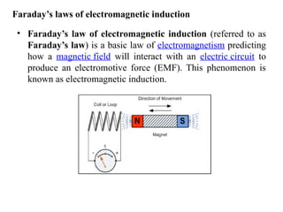
Faraday’s laws ofelectromagnetic induction
• Faraday’s law of electromagnetic induction (referred to as
Faraday’s law) is a basic law of electromagnetism predicting
how a magnetic field will interact with an electric circuit to
produce an electromotive force (EMF). This phenomenon is
known as electromagnetic induction.
4.
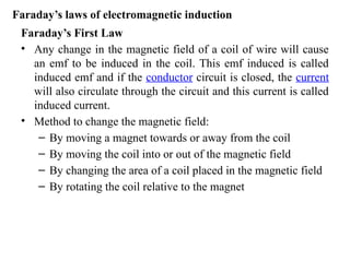
Faraday’s First Law
•Any change in the magnetic field of a coil of wire will cause
an emf to be induced in the coil. This emf induced is called
induced emf and if the conductor circuit is closed, the current
will also circulate through the circuit and this current is called
induced current.
• Method to change the magnetic field:
– By moving a magnet towards or away from the coil
– By moving the coil into or out of the magnetic field
– By changing the area of a coil placed in the magnetic field
– By rotating the coil relative to the magnet
Faraday’s laws of electromagnetic induction
5.
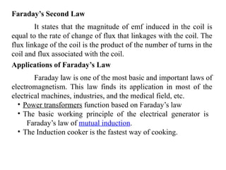
Faraday’s Second Law
Itstates that the magnitude of emf induced in the coil is
equal to the rate of change of flux that linkages with the coil. The
flux linkage of the coil is the product of the number of turns in the
coil and flux associated with the coil.
Applications of Faraday’s Law
Faraday law is one of the most basic and important laws of
electromagnetism. This law finds its application in most of the
electrical machines, industries, and the medical field, etc.
• Power transformers function based on Faraday’s law
• The basic working principle of the electrical generator is
Faraday’s law of mutual induction.
• The Induction cooker is the fastest way of cooking.
6.
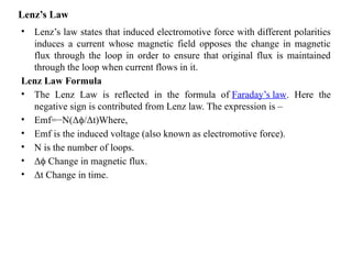
Lenz’s Law
• Lenz’slaw states that induced electromotive force with different polarities
induces a current whose magnetic field opposes the change in magnetic
flux through the loop in order to ensure that original flux is maintained
through the loop when current flows in it.
Lenz Law Formula
• The Lenz Law is reflected in the formula of Faraday’s law. Here the
negative sign is contributed from Lenz law. The expression is –
• Emf=−N(Δ /Δt)Where,
ϕ
• Emf is the induced voltage (also known as electromotive force).
• N is the number of loops.
• Δ Change in magnetic flux.
ϕ
• Δt Change in time.
7.
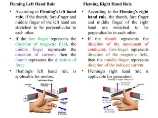
Fleming Left HandRule
• According to Fleming's left hand
rule, if the thumb, fore-finger and
middle finger of the left hand are
stretched to be perpendicular to
each other.
• If the fore finger represents the
direction of magnetic field, the
middle finger represents the
direction of current, then the
thumb represents the direction of
force.
• Fleming's left hand rule is
applicable for motors.
Fleming Right Hand Rule
• According to the Fleming's right
hand rule, the thumb, fore finger
and middle finger of the right
hand are stretched to be
perpendicular to each other.
• If the thumb represents the
direction of the movement of
conductor, fore-finger represents
direction of the magnetic field,
then the middle finger represents
direction of the induced current.
• Fleming's right hand rule is
applicable for generators.
8.
Introduction:
• The Devicewhich Converts the Mechanical Energy into Electrical Energy
is called Generator.
• There are Two types of Generators
1. D.C Generator:- The Generator which converts the Mechanical Energy
into D.C Form of Electrical Energy is called D.C Generator.
2. A.C Generator:- The Generator which converts the Mechanical Energy
into A.C Form of Electrical Energy is called A.C Generator.
• Both of the Generator Works on the Principle of Faraday’s Law of
Electromagnetic Induction.
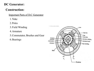
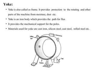
Yoke:
• Yoke isalso called as frame. It provides protection to the rotating and other
parts of the machine from moisture, dust etc.
• Yoke is an iron body which provides the path for flux
• It provides the mechanical support for the poles.
• Materials used for yoke are cast iron, silicon steel, cast steel, rolled steel etc.
11.
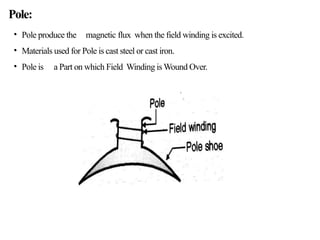
Pole:
• Pole producethe magnetic flux when the field winding is excited.
• Materials used for Pole is cast steel or cast iron.
• Pole is a Part on which Field Winding is Wound Over.
12.
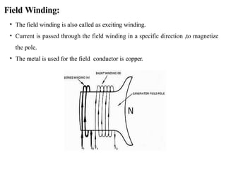
Field Winding:
• Thefield winding is also called as exciting winding.
• Current is passed through the field winding in a specific direction ,to magnetize
the pole.
• The metal is used for the field conductor is copper.
13.
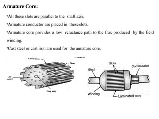
Armature Core:
•All theseslots are parallel to the shaft axis.
•Armature conductor are placed in these slots.
•Armature core provides a low reluctance path to the flux produced by the field
winding.
•Cast steel or cast iron are used for the armature core.
14.
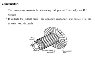
Commutator:
• The commutatorconverts the alternating emf, generated internally in a D.C.
voltage
• It collects the current from the armature conductors and passes it to the
external load via brush.
15.
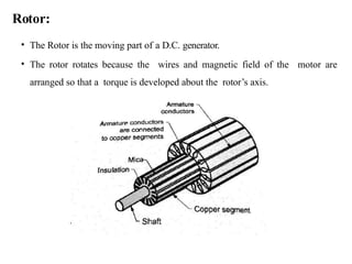
Rotor:
• The Rotoris the moving part of a D.C. generator.
• The rotor rotates because the wires and magnetic field of the motor are
arranged so that a torque is developed about the rotor’s axis.
16.
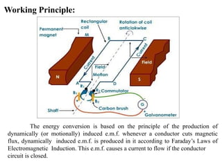
Working Principle:
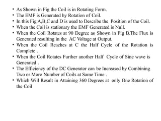
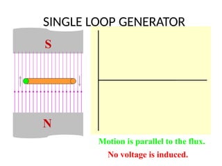
The energyconversion is based on the principle of the production of
dynamically (or motionally) induced e.m.f. whenever a conductor cuts magnetic
flux, dynamically induced e.m.f. is produced in it according to Faraday’s Laws of
Electromagnetic Induction. This e.m.f. causes a current to flow if the conductor
circuit is closed.
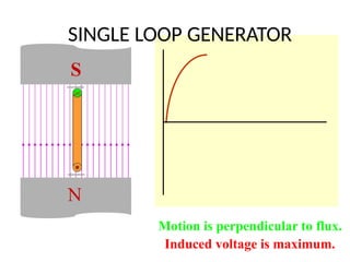
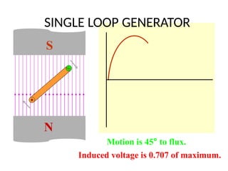
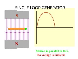
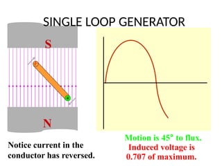
18.
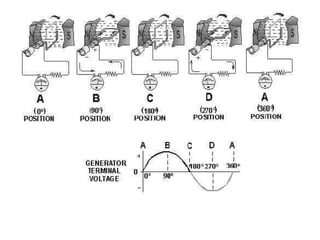
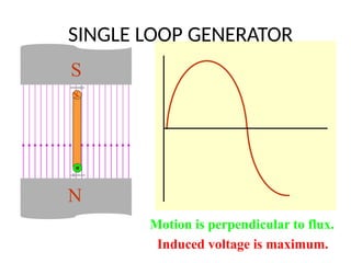
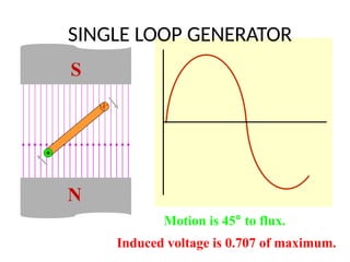
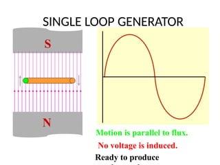
• As Shownin Fig the Coil is in Rotating Form.
• The EMF is Generated by Rotation of Coil.
• In this Fig A,B,C and D is used to Describe the Position of the Coil.
• When the Coil is stationary the EMF Generated is Null.
• When the Coil Rotates at 90 Degree as Shown in Fig B.The Flux is
Generated resulting in the AC Voltage at Output.
• When the Coil Reaches at C the Half Cycle of the Rotation is
Complete .
• When the Coil Rotates Further another Half Cycle of Sine wave is
Generated .
• The Efficiency of the DC Generator can be Increased by Combining
Two or More Number of Coils at Same Time .
• Which Will Result in Attaining 360 Degrees at only One Rotation of
the Coil
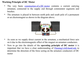
Working Principle ofDC Motor
• The very basic construction of a DC motor contains a current carrying
armature, connected to the supply end through commutator segments and
brushes.
• The armature is placed in between north pole and south pole of a permanent
or an electromagnet as shown in the diagram above.
• As soon as we supply direct current in the armature, a mechanical force acts
on it due to the electromagnetic effect of the magnet on armature conductors.
• Now to go into the details of the operating principle of DC motor it is
important that we have a clear understanding of Fleming’s left-hand rule to
determine the direction of the force acting on the armature conductors of DC
motor
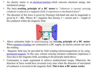
30.
• An electricmotor is an electrical machine which converts electrical energy into
mechanical energy.
• The basic working principle of a DC motor is: "whenever a current carrying
conductor is placed in a magnetic field, it experiences a mechanical force".
• The direction of this force is given by Fleming's left-hand rule and its magnitude is
given by F = BIL. Where, B = magnetic flux density, I = current and L = length of
the conductor within the magnetic field.
• Above animation helps in understanding the working principle of a DC motor.
When armature windings are connected to a DC supply, an electric current sets up in
the winding.
• Magnetic field may be provided by field winding (electromagnetism) or by using
permanent magnets. In this case, current carrying armature conductors experience a
force due to the magnetic field, according to the principle stated above.
• Commutator is made segmented to achieve unidirectional torque. Otherwise, the
direction of force would have reversed every time when the direction of movement
of conductor is reversed in the magnetic field. This is how a DC motor works!
31.
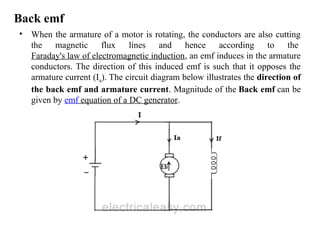
Back emf
• Whenthe armature of a motor is rotating, the conductors are also cutting
the magnetic flux lines and hence according to the
Faraday's law of electromagnetic induction, an emf induces in the armature
conductors. The direction of this induced emf is such that it opposes the
armature current (Ia). The circuit diagram below illustrates the direction of
the back emf and armature current. Magnitude of the Back emf can be
given by emf equation of a DC generator.
32.
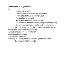
Emf equation ofDC generator.
Let
= flux/pole in weber
Z = total number of armature conductors
= No.of slots No.of conductors/slot
P = No.of generator poles
A = No.of parallel paths in armature
N = Armature rotation in revolution per minute (rpm)
E = emf induced in any parallel path in armature
Eg = Generated emf in any one of the parallel paths
Average emf generated per conductor
Flux cut/conductor in one revolution
No.of revolutions/second
Time for one revolution,
According to Faraday’s law of electromagnetic induction,
E.M.F generated/conductor
33.
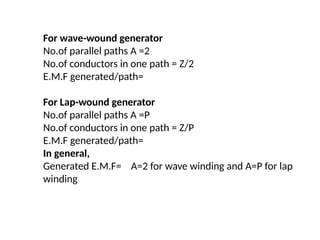
For wave-wound generator
No.ofparallel paths A =2
No.of conductors in one path = Z/2
E.M.F generated/path=
For Lap-wound generator
No.of parallel paths A =P
No.of conductors in one path = Z/P
E.M.F generated/path=
In general,
Generated E.M.F= A=2 for wave winding and A=P for lap
winding
34.
Transformer
An A.C. deviceused to change high voltage low current A.C. into
low voltage high current A.C. and vice-versa without changing
the frequency
In brief,
1. Transfers electric power from one circuit to another
2. It does so without a change of frequency
3. It accomplishes this by electromagnetic induction
4. Where the two electric circuits are in mutual inductive
influence of each other.
35.
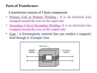
Parts of Transformer:
Atransformer consists of 3 basic components
• Primary Coil or Primary Winding : It is an electrical wire
wrapped around the core on the input side
• Secondary Coil or Secondary Winding: It is an electrical wire
wrapped around the core on the output side
• Core : A ferromagnetic material that can conduct a magnetic
field through it. Example: Iron
36.
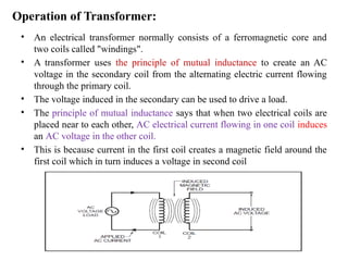
Operation of Transformer:
•An electrical transformer normally consists of a ferromagnetic core and
two coils called "windings".
• A transformer uses the principle of mutual inductance to create an AC
voltage in the secondary coil from the alternating electric current flowing
through the primary coil.
• The voltage induced in the secondary can be used to drive a load.
• The principle of mutual inductance says that when two electrical coils are
placed near to each other, AC electrical current flowing in one coil induces
an AC voltage in the other coil.
• This is because current in the first coil creates a magnetic field around the
first coil which in turn induces a voltage in second coil
37.
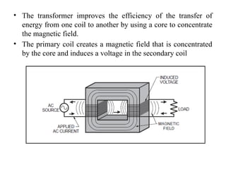
• The transformerimproves the efficiency of the transfer of
energy from one coil to another by using a core to concentrate
the magnetic field.
• The primary coil creates a magnetic field that is concentrated
by the core and induces a voltage in the secondary coil
38.
AC Machines (Single Phase Induction Motor)
• Single-phase a.c supply is commonly used for lighting purpose
in shops, offices, houses, schools etc..Hence instead of d.c
motors, the motors which work on single-phase a.c. supply are
popularly used. These a.c motors are called single-phase
induction motors. A large no. of domestic applications
use single-phase induction motors.
• The power rating of these motors is very small. Some of them
are even fractional horsepower motors, which are used in
applications like small toys, small fans, hairdryers etc. This
article explains the construction, working principle of
single-phase induction motors.
39.
Construction:
• Similar toa d.c motor, single-phase induction motor also has two main parts,
one rotating and other stationary.
• The stationary part in single-phase induction motors is Stator and the rotating
part is Rotor.
• The stator has laminated construction, made up of stampings.
• The stampings are lotted on its periphery to carry the winding called stator
winding or main winding.
• This is excited by a single-phase a.c supply.
• The laminated construction keeps iron losses to the minimum.
• The stampings are made up of material from silicon steel which minimize the
hysteresis loss.
• The stator winding is wound for a certain definite number of poles means when
excited by single-phase a.c supply, stator produces the magnetic field which
creates the effect of the certain definite number of poles.
• The number of poles for which stator winding is wound decides the
synchronous speed of the motor.
• The synchronous speed is denoted as Ns and it has a fixed relation with supply
frequency f and number of poles P. The relation is given by,
Ns = 120f/p RPM
40.
Working Principle
• Forthe motoring action, there must exist two fluxes which interact with each other to
produce the torque.
• In d.c motors, field winding produces the main flux while d.c supply given to armature is
responsible to produce armature flux.
• The main flux and armature flux interact to produce the torque.
• In the single-phase induction motor, single-phase a.c supply is given to the stator
winding.
• The stator winding carries an alternating current which produces the flux which is also
alternating in nature.
• This flux is called the main flux.
• This flux links with the rotor conductors and due to transformer action e.m.f gets induced
in the rotor.
• The induced emf drives current through the rotor as the rotor circuit is the closed circuit.
• This rotor current produces another flux called rotor flux required for the motoring action.
• Thus second flux is produced according to the induction principle due to induced e.m.f
hence the motor is called induction motor.
• As against this in d.c motor a separate supply is required to the armature to produce
armature flux.
• This is an important difference between d.c motor and an induction motor.
41.
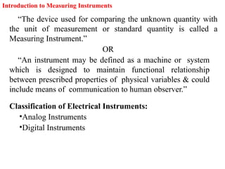
Introduction to MeasuringInstruments
“The device used for comparing the unknown quantity with
the unit of measurement or standard quantity is called a
Measuring Instrument.”
OR
“An instrument may be defined as a machine or system
which is designed to maintain functional relationship
between prescribed properties of physical variables & could
include means of communication to human observer.”
Classification of Electrical Instruments:
•Analog Instruments
•Digital Instruments
42.
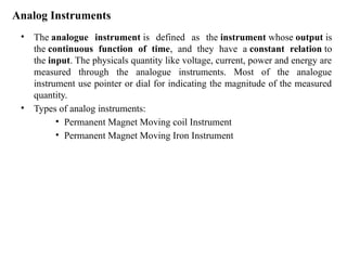
Analog Instruments
• Theanalogue instrument is defined as the instrument whose output is
the continuous function of time, and they have a constant relation to
the input. The physicals quantity like voltage, current, power and energy are
measured through the analogue instruments. Most of the analogue
instrument use pointer or dial for indicating the magnitude of the measured
quantity.
• Types of analog instruments:
• Permanent Magnet Moving coil Instrument
• Permanent Magnet Moving Iron Instrument
43.
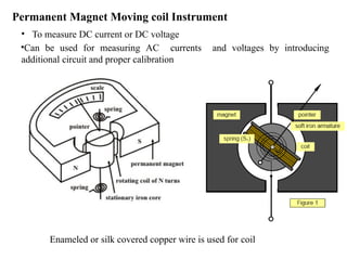
Permanent Magnet Movingcoil Instrument
• To measure DC current or DC voltage
•Can be used for measuring AC currents and voltages by introducing
additional circuit and proper calibration
Enameled or silk covered copper wire is used for coil
45.
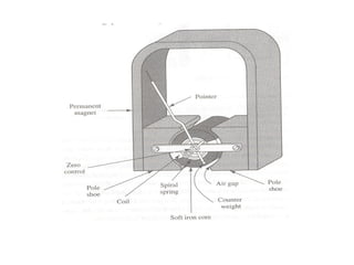
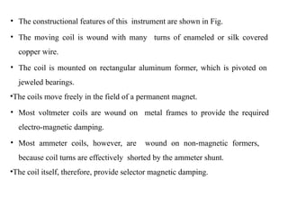
• The constructionalfeatures of this instrument are shown in Fig.
• The moving coil is wound with many turns of enameled or silk covered
copper wire.
• The coil is mounted on rectangular aluminum former, which is pivoted on
jeweled bearings.
•The coils move freely in the field of a permanent magnet.
• Most voltmeter coils are wound on metal frames to provide the required
electro-magnetic damping.
• Most ammeter coils, however, are wound on non-magnetic formers,
because coil turns are effectively shorted by the ammeter shunt.
•The coil itself, therefore, provide selector magnetic damping.
46.
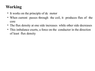
Working
• It workson the principle of dc motor
• When current passes through the coil, it produces flux of the
core
• The flux density at one side increases while other side decreases
• This imbalance exerts, a force on the conductor in the direction
of least flux density
47.
Advantage
• The PMMCconsumes less power and has great
accuracy.
• It has uniformly divided scale and can cover arc
of 270 degree.
• The PMMC has a high torque to weight ratio.
• It can be modified as ammeter or voltmeter with suitable
resistance.
• It has efficient damping characteristics and is not affected
by stray magnetic field.
•It produces no losses due to hysteresis.
48.
Disadvantage
• The movingcoil instrument can only be used on D.C supply as
the reversal of current produces reversal of torque on the coil.
• It’s very delicate and sometimes uses ac circuit with a
rectifier.
• It’s costly as compared to moving coil iron instruments.
• It may show error due to loss of magnetism of
permanent magnet.
• You may also read Minimize the risk of electrical shock
on ship.
49.
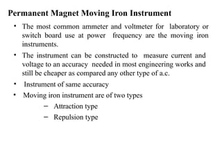
Permanent Magnet MovingIron Instrument
• The most common ammeter and voltmeter for laboratory or
switch board use at power frequency are the moving iron
instruments.
• The instrument can be constructed to measure current and
voltage to an accuracy needed in most engineering works and
still be cheaper as compared any other type of a.c.
• Instrument of same accuracy
• Moving iron instrument are of two types
– Attraction type
– Repulsion type
50.
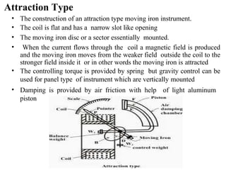
Attraction Type
• Theconstruction of an attraction type moving iron instrument.
• The coil is flat and has a narrow slot like opening
• The moving iron disc or a sector essentially mounted.
• When the current flows through the coil a magnetic field is produced
and the moving iron moves from the weaker field outside the coil to the
stronger field inside it or in other words the moving iron is attracted
• The controlling torque is provided by spring but gravity control can be
used for panel type of instrument which are vertically mounted
• Damping is provided by air friction with help of light aluminum
piston
51.
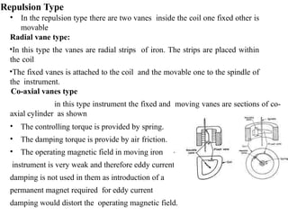
Repulsion Type
• Inthe repulsion type there are two vanes inside the coil one fixed other is
movable
Radial vane type:
•In this type the vanes are radial strips of iron. The strips are placed within
the coil
•The fixed vanes is attached to the coil and the movable one to the spindle of
the instrument.
Co-axial vanes type
in this type instrument the fixed and moving vanes are sections of co-
axial cylinder as shown
• The controlling torque is provided by spring.
• The damping torque is provide by air friction.
• The operating magnetic field in moving iron
instrument is very weak and therefore eddy current
damping is not used in them as introduction of a
permanent magnet required for eddy current
damping would distort the operating magnetic field.
53.
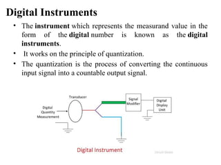
Digital Instruments
• Theinstrument which represents the measurand value in the
form of the digital number is known as the digital
instruments.
• It works on the principle of quantization.
• The quantization is the process of converting the continuous
input signal into a countable output signal.
54.
Advantages of DigitalInstrument
1.The digital instruments display the reading in the numeric form which reduces the
error.
2.The digital output is obtained by the instrument which acts as an input for the
memorable devices like floppy, recorder, printer etc.
3.The power consumption is less in the digital instruments.
Disadvantages of Digital Instruments
The following are the disadvantages of the digital electronics.
4.The overloading capacity of the instrument is low.
5.It is a temperature sensitive device.The digital instrument is made by the very
delicate element which is easily affected by the atmospheric condition.
6.The effect of noise is more on digital electronics as compared to the analogue
instruments.
55.
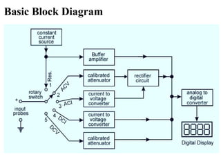
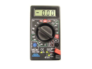
Digital Multimeter
The digitalmultimeter is a versatile instrument that
contains three different meters in one.
• A voltmeter measures the voltage across a component (in
volts).
• An ohmmeter measures the resistance of a component
(in ohms).
• An ammeter measures the amount of current through a
component (in amperes, or amps).
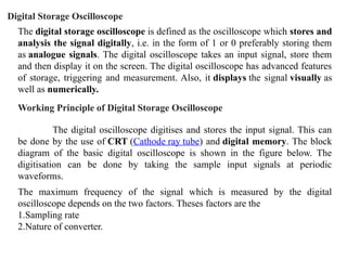
The digital storageoscilloscope is defined as the oscilloscope which stores and
analysis the signal digitally, i.e. in the form of 1 or 0 preferably storing them
as analogue signals. The digital oscilloscope takes an input signal, store them
and then display it on the screen. The digital oscilloscope has advanced features
of storage, triggering and measurement. Also, it displays the signal visually as
well as numerically.
Digital Storage Oscilloscope
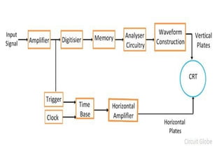
Working Principle of Digital Storage Oscilloscope
The digital oscilloscope digitises and stores the input signal. This can
be done by the use of CRT (Cathode ray tube) and digital memory. The block
diagram of the basic digital oscilloscope is shown in the figure below. The
digitisation can be done by taking the sample input signals at periodic
waveforms.
The maximum frequency of the signal which is measured by the digital
oscilloscope depends on the two factors. Theses factors are the
1.Sampling rate
2.Nature of converter.
60.
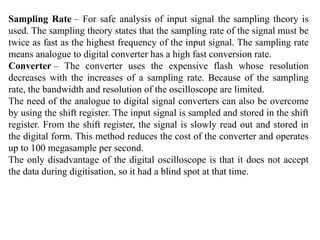
Sampling Rate –For safe analysis of input signal the sampling theory is
used. The sampling theory states that the sampling rate of the signal must be
twice as fast as the highest frequency of the input signal. The sampling rate
means analogue to digital converter has a high fast conversion rate.
Converter – The converter uses the expensive flash whose resolution
decreases with the increases of a sampling rate. Because of the sampling
rate, the bandwidth and resolution of the oscilloscope are limited.
The need of the analogue to digital signal converters can also be overcome
by using the shift register. The input signal is sampled and stored in the shift
register. From the shift register, the signal is slowly read out and stored in
the digital form. This method reduces the cost of the converter and operates
up to 100 megasample per second.
The only disadvantage of the digital oscilloscope is that it does not accept
the data during digitisation, so it had a blind spot at that time.