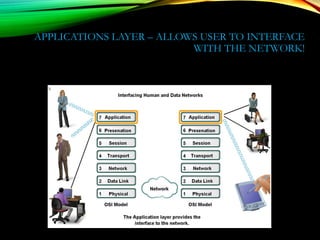
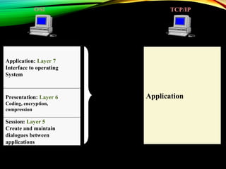
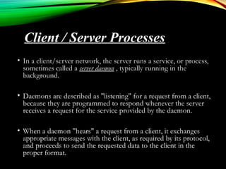
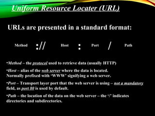
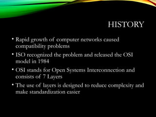
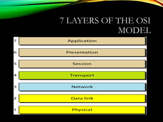
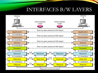
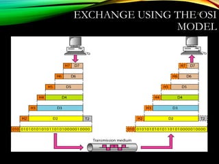
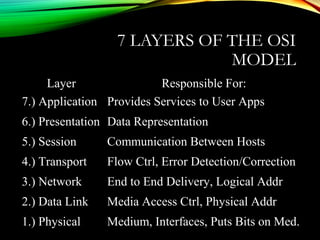
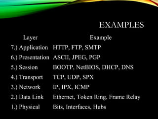
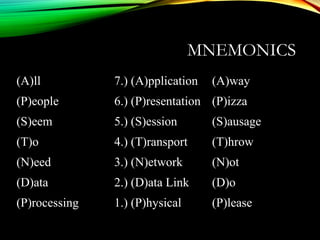
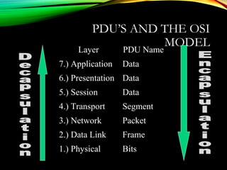
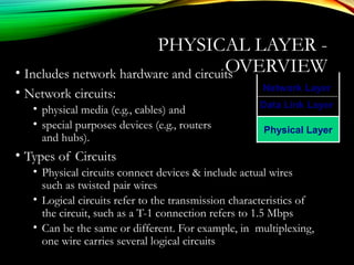
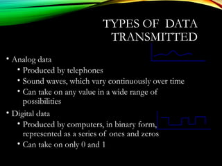
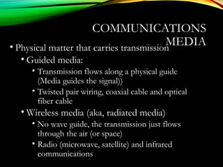
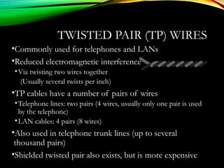
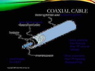
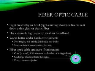
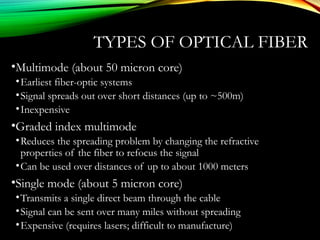
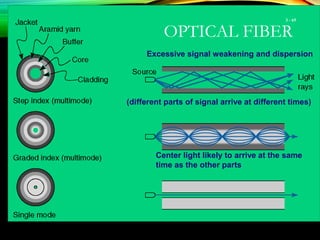
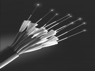
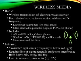
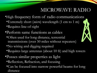
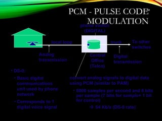
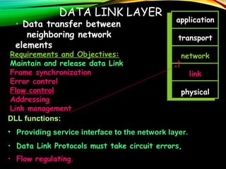
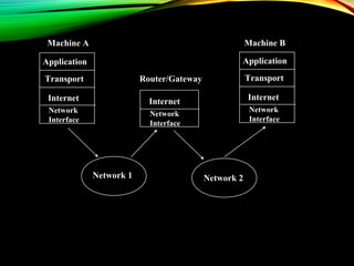
The document discusses computer network models and the physical layer of the OSI model. It provides an overview of the OSI model and its seven layers. It describes the physical layer in detail, including its responsibilities of defining the physical medium and interfaces. Various types of communication media are discussed, including twisted pair wires, coaxial cable, fiber optic cable, and wireless technologies like radio, microwave, satellite, and infrared. The physical layer controls transmission rates and modes and ensures bits are transmitted from one node to the next.


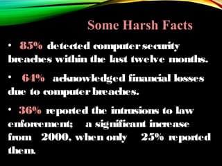
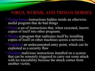


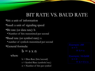
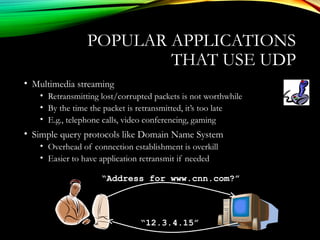
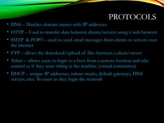
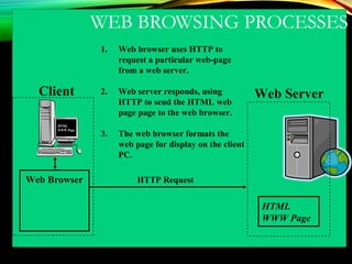
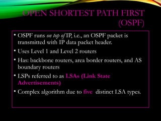
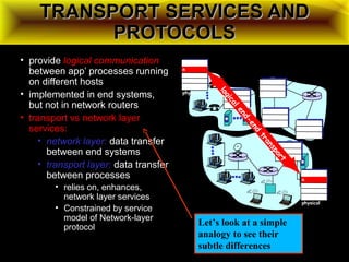
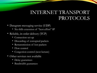
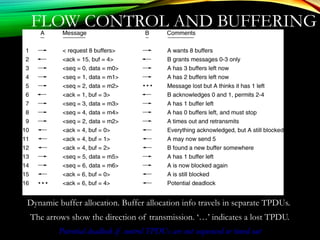
![SHORTEST PATH ROUTING
1. Bellman-Ford Algorithm [Distance Vector]
2. Dijkstra’s Algorithm [Link State]
What does it mean to be the shortest (or optimal)
route?
a. Minimize mean packet delay
b. Maximize the network throughput
c. Mininize the number of hops along the path](https://image.slidesharecdn.com/datacommunicationresearch-171015142311/85/DATA-COMMUNICATION-PPT-171-320.jpg)
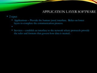
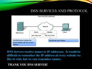
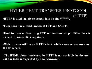
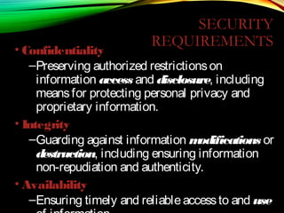
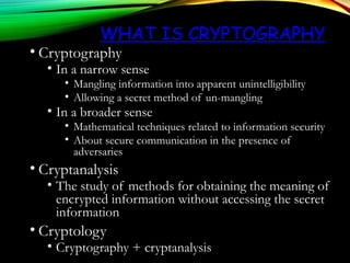
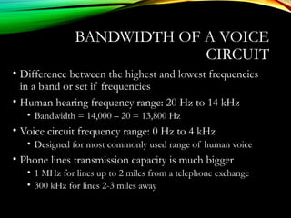
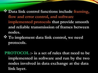
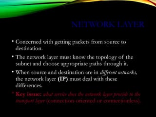
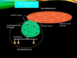
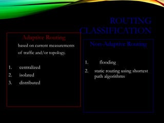
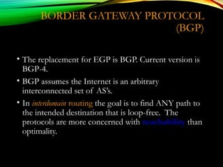
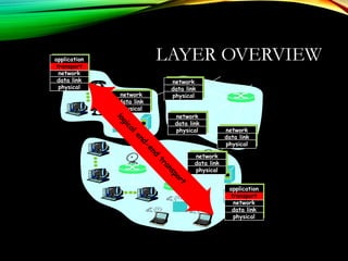
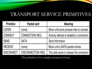
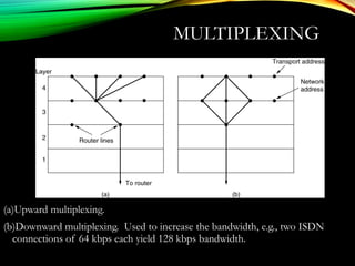
![INTERNETWORK ROUTING
[HALSALL]
Adaptive Routing
Centralized Distributed
Intradomain routing Interdomain routing
Distance Vector routing Link State routing
[IGP] [EGP]
[BGP,IDRP]
[OSPF,IS-IS,PNNI][RIP]
[RCC]
Interior
Gateway Protocols
Exterior
Gateway Protocols](https://image.slidesharecdn.com/datacommunicationresearch-171015142311/85/DATA-COMMUNICATION-PPT-173-320.jpg)
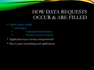
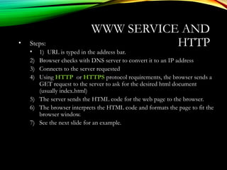
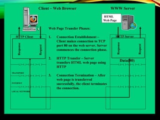
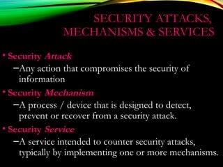
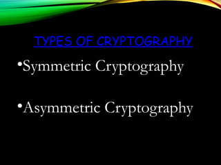
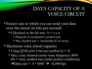
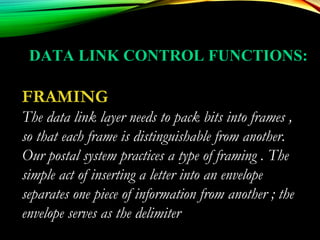
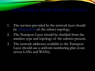
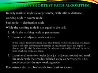
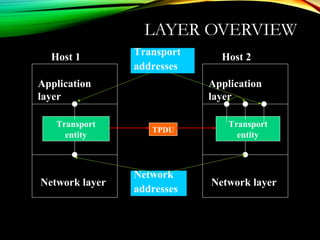
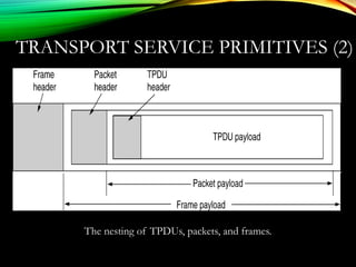
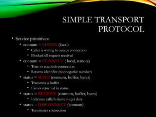
![DISTANCE VECTOR ALGORITHM
[PERLMAN]
1. Router transmits its distance vector to each of its
neighbors.
2. Each router receives and saves the most recently
received distance vector from each of its neighbors.
3. A router recalculates its distance vector when:
a. It receives a distance vector from a neighbor containing
different information than before.
b. It discovers that a link to a neighbor has gone down (i.e., a
topology change).
The DV calculation is based on minimizing the cost to
each destination.](https://image.slidesharecdn.com/datacommunicationresearch-171015142311/85/DATA-COMMUNICATION-PPT-176-320.jpg)
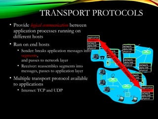
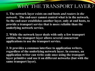
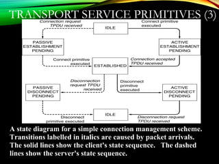
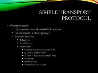

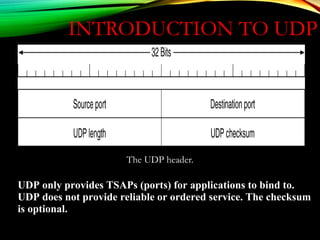
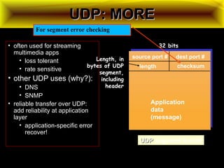
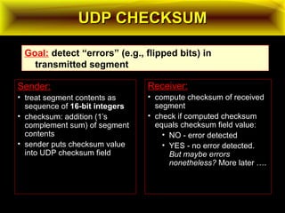
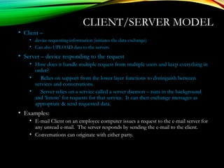
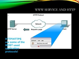
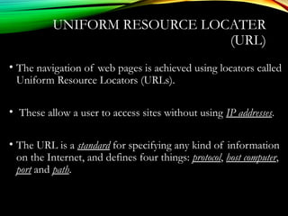
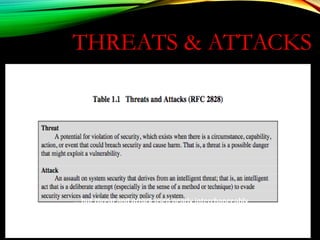
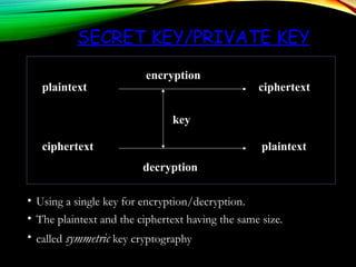
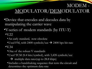
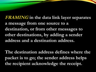
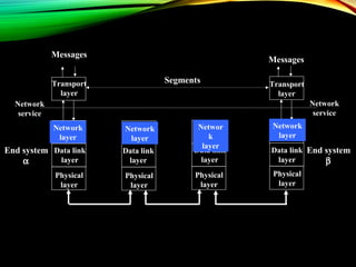
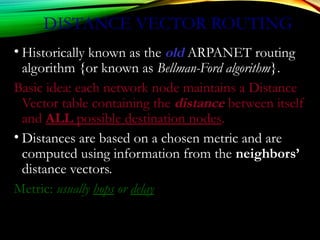
![UDPUDP: USER DATAGRAM PROTOCOL: USER DATAGRAM PROTOCOL
[RFC 768][RFC 768]
• “no frills,” “bare bones”
Internet transport protocol
• “best effort” service, UDP
segments may be:
• lost
• delivered out of order to
app
• connectionless:
• no handshaking between
UDP sender, receiver
• each UDP segment
handled independently of
others
Why is there a UDP?
• no connection establishment
(which can add delay)
• simple: no connection state at
sender, receiver
• small segment header
• no congestion control: UDP
can blast away as fast as
desired
Additional functionalities are implemented by the application
TCP – 20 bytes, UDP – 8 bytes](https://image.slidesharecdn.com/datacommunicationresearch-171015142311/85/DATA-COMMUNICATION-PPT-211-320.jpg)