Downloaded 53 times
![International Journal of Engineering Research and Development
ISSN: 2278-067X, Volume 1, Issue 12 (July 2012), PP.27-32
www.ijerd.com
Design Analysis of Slotted Diagonal Shape Patch Antenna with
Hybrid Coupler
A.Sahaya Anselin Nisha 1, T.Jayanthy2
1
Research Scholar, Sathyabama University, Chennai - 600119, India
2
Principal, Panimalar Institute of Technology, Chennai-602103, India.
Abstract—In this paper hybrid coupler connected diagonal shaped patch antenna with slot is examined. Theoretical
performance is carried out using advanced system design (ADS) software. Measurement of antenna parameters like
return loss, standing wave ratio also have been presented in this article. The measured values for the antenna are taken
by agilent E5062A network analyzer. Simulated and measured results are having good agreement. The effect of excited
two orthogonal modes with equal amplitude and 90 degree phase shift coupler connected with patch will produce circular
polarization. The antenna is having gain of 3.319dB and the directivity of 6.98dB. The proposed antenna can be useful in
wireless applications.
Keywords— Advanced Design System, Circular Polarization, C band, Network Analyser, Patch antenna
I. INTRODUCTION
Microstrip patch antennas are placing vital role in personal communication systems because of its tremendous
advantages of light weight, thin profile and low cost [1]. The other side micro strip patch antenna having great disadvantage
is narrow bandwidth. Many techniques are introduced to improve the bandwidth for example multilayer, thick substrate [2].
Patch can be in any shape like rectangular, Circular, Square, Elliptical, Triangular etc [3]. Hybrid coupler
implementation with Varactor diode and Pin diode is proposed by S. Cheng, K-O. Sun, [ 4 , 5 ] . Commercial
wireless systems require low cost antenna with large bandwidth, slot antennas satisfying these requirements [6, 7]. By
introducing Log periodic microstrip antennas [8,9], different types of feeding techniques [10-14] bandwidth is enhanced in
wireless applications. Circular polarization antenna have been proposed and studied over the past few years [15-19]. In this
design a new shaped microstrip antenna is introduced and the hybrid coupler is connected to get circular polarization. The
design concept comes from circularly polarized antenna with conical beam [20].
II. MICROSTRIP ANTENNA
Microstrip or patch antennas are becoming increasingly useful because they can be printed directly onto a circuit
board. They are becoming very widespread within the mobile phone market. They are low cost, have a low profile and are
easily fabricated. Discontinuities are present in microstrip antenna to produce electric and magnetic field distributions [21].
The fig 1 shows the geometry of the microstrip patch antenna. This patch antenna is having the ground plane and dielectric
which would be underneath. The length L causes resonance at its half-wavelength frequency. The radiating edges are at the
ends of the L-dimension of the rectangle, which sets up the single polarization. Radiation that occurs at the ends of the W-
dimension is far less and is referred to as the cross polarization. The thickness of the ground plane is not critically impor tant.
Typically the height h is much smaller than the wavelength of operation. In GPS receivers the size of portable
communication device is very important [22]. The square ring microstrip antenna design is having very small size of
antenna proposed by J.S.Row [23]. To reduce the size of square patch antenna slits are introduced at the corner of antenna.
Phase detection and the circularly polarized antenna is produced by a square patch antenna with feed point on the diagonal.
Slot antennas will be having wider circular polarization bandwidth than single feed circularly polarized antenna. In this
paper a novel design of microstrip octagonal shaped patch antenna is proposed for wireless applications.
III. HYBRID COUPLER DESIGN
Hybrid couplers normally split an input signal into two unequal amplitude outputs. It is a four port device with one
input, two outputs and one isolated port. At ideal condition input port power is equal to sum of two output port power ie 90
degree phase shift between these ports. Termination impedance is connected with the isolated port. According to the
impedance choice of the series and stub microstrip transmission lines we can calculate the w/d ratios of those lines in
microstrip form by using the following formulas: Width of Hybrid (w) is as follows
8eA w
w 2A − 2
<2
= e d Eq. 1
d 2 ɛr − 1 0.61 w
B − 1 − ln 2B − 1 + ln B − 1 + 0.39 − >2
π 2ɛr ɛr d
27](https://image.slidesharecdn.com/d01122732-120716060910-phpapp01/85/IJERD-www-ijerd-com-International-Journal-of-Engineering-Research-and-Development-1-320.jpg)
![International Journal of Engineering Research and Development
ISSN: 2278-067X, Volume 1, Issue 12 (July 2012), PP.27-32
www.ijerd.com
Design Analysis of Slotted Diagonal Shape Patch Antenna with
Hybrid Coupler
A.Sahaya Anselin Nisha 1, T.Jayanthy2
1
Research Scholar, Sathyabama University, Chennai - 600119, India
2
Principal, Panimalar Institute of Technology, Chennai-602103, India.
Abstract—In this paper hybrid coupler connected diagonal shaped patch antenna with slot is examined. Theoretical
performance is carried out using advanced system design (ADS) software. Measurement of antenna parameters like
return loss, standing wave ratio also have been presented in this article. The measured values for the antenna are taken
by agilent E5062A network analyzer. Simulated and measured results are having good agreement. The effect of excited
two orthogonal modes with equal amplitude and 90 degree phase shift coupler connected with patch will produce circular
polarization. The antenna is having gain of 3.319dB and the directivity of 6.98dB. The proposed antenna can be useful in
wireless applications.
Keywords— Advanced Design System, Circular Polarization, C band, Network Analyser, Patch antenna
I. INTRODUCTION
Microstrip patch antennas are placing vital role in personal communication systems because of its tremendous
advantages of light weight, thin profile and low cost [1]. The other side micro strip patch antenna having great disadvantage
is narrow bandwidth. Many techniques are introduced to improve the bandwidth for example multilayer, thick substrate [2].
Patch can be in any shape like rectangular, Circular, Square, Elliptical, Triangular etc [3]. Hybrid coupler
implementation with Varactor diode and Pin diode is proposed by S. Cheng, K-O. Sun, [ 4 , 5 ] . Commercial
wireless systems require low cost antenna with large bandwidth, slot antennas satisfying these requirements [6, 7]. By
introducing Log periodic microstrip antennas [8,9], different types of feeding techniques [10-14] bandwidth is enhanced in
wireless applications. Circular polarization antenna have been proposed and studied over the past few years [15-19]. In this
design a new shaped microstrip antenna is introduced and the hybrid coupler is connected to get circular polarization. The
design concept comes from circularly polarized antenna with conical beam [20].
II. MICROSTRIP ANTENNA
Microstrip or patch antennas are becoming increasingly useful because they can be printed directly onto a circuit
board. They are becoming very widespread within the mobile phone market. They are low cost, have a low profile and are
easily fabricated. Discontinuities are present in microstrip antenna to produce electric and magnetic field distributions [21].
The fig 1 shows the geometry of the microstrip patch antenna. This patch antenna is having the ground plane and dielectric
which would be underneath. The length L causes resonance at its half-wavelength frequency. The radiating edges are at the
ends of the L-dimension of the rectangle, which sets up the single polarization. Radiation that occurs at the ends of the W-
dimension is far less and is referred to as the cross polarization. The thickness of the ground plane is not critically impor tant.
Typically the height h is much smaller than the wavelength of operation. In GPS receivers the size of portable
communication device is very important [22]. The square ring microstrip antenna design is having very small size of
antenna proposed by J.S.Row [23]. To reduce the size of square patch antenna slits are introduced at the corner of antenna.
Phase detection and the circularly polarized antenna is produced by a square patch antenna with feed point on the diagonal.
Slot antennas will be having wider circular polarization bandwidth than single feed circularly polarized antenna. In this
paper a novel design of microstrip octagonal shaped patch antenna is proposed for wireless applications.
III. HYBRID COUPLER DESIGN
Hybrid couplers normally split an input signal into two unequal amplitude outputs. It is a four port device with one
input, two outputs and one isolated port. At ideal condition input port power is equal to sum of two output port power ie 90
degree phase shift between these ports. Termination impedance is connected with the isolated port. According to the
impedance choice of the series and stub microstrip transmission lines we can calculate the w/d ratios of those lines in
microstrip form by using the following formulas: Width of Hybrid (w) is as follows
8eA w
w 2A − 2
<2
= e d Eq. 1
d 2 ɛr − 1 0.61 w
B − 1 − ln 2B − 1 + ln B − 1 + 0.39 − >2
π 2ɛr ɛr d
27](https://image.slidesharecdn.com/d01122732-120716060910-phpapp01/75/IJERD-www-ijerd-com-International-Journal-of-Engineering-Research-and-Development-1-2048.jpg)
![Design Analysis of Slotted Diagonal Shape Patch Antenna with Hybrid Coupler
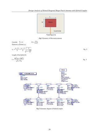
Fig 7 Measured Characteristic of VSWR
S11
200
100
Phase [deg]
0
-100
-200
2.0 2.2 2.4 2.6 2.8 3.0
Frequency
Fig 8 Phase Characteristic of proposed antenna
Fig 9 Radiation pattern of proposed antenna
VI. CONCLUSION
A new feeding technique is introduced in this paper. Circular polarization is achieved by connecting directly
hybrid coupler to radiating element. The return loss value is greater than -10dB so the proposed antenna can be useful in the
field of wireless application. Proposed antenna also having high directivity.
31](https://image.slidesharecdn.com/d01122732-120716060910-phpapp01/85/IJERD-www-ijerd-com-International-Journal-of-Engineering-Research-and-Development-5-320.jpg)
![Design Analysis of Slotted Diagonal Shape Patch Antenna with Hybrid Coupler
REFERENCES
[1]. Bahl, J. and P. Bhartia, Microstrip Antennas, Artech House, Inc., London, 1980.
[2]. James, J. R. and P. S. Hall, Handbook of Microstrip Antennas,Peter Peregronic Ltd., London, 1989.
[3]. N.T. Tokan and F. Gune¸, “support vector characterization of the microstrip antennas based on
¨ s
measurements”, Progress In Electromagnetics Research B, Vol. 5, 49–61, 2008.
[4]. S. Cheng, E. Ojefors, P. Hallbjorner, A. Rydberg, “Compact reflective microstrip phase shifter for traveling wave antenna
applications ,” IEEE Microwave & Wireless Components Letters, vol. 16, pp. 431-433, July 2006.
[5]. K-O. Sun, C-C. Yen, D. Van der Weide, “A size reduced reflection-mode phase shifter,” Mic. & Opt. Tech. Letters, Vol.
47, pp. 457-459, Dec. 2005.
[6]. Eldek, A. A., A. Z. Elsherbeni, C. E. Smith, and K.-F. Lee,“Wideband slot antennas for radar applications,” Proc. IEEE Radar
Conf., 79–84, Huntsville, AL, May 2003.
[7]. Neto, N. Llombart, G. Gerini, and P. de Maagt, “On the optimal radiation bandwidth of printed slot antennas surrounded by
EBGs,” IEEE Trans. Antennas Propag., vol. 54, no. 4, pp. 1074–1082, Apr. 2006.
[8]. P. S. Hall, “New wideband microstrip antenna using log-periodic technique,” Electron. Lett., vol. 16, no. 4, pp. 127–128, 1980.
[9]. P. S. Hall, “Multi-octave bandwidth log-periodic microstrip antenna array,” Proc. Inst. Elect. Eng. Microw., Antennas Propag.,
vol. 133, no. 2, pt. H, pp. 127–136, 1986.
[10]. H. Pues, J. Bogaers, R. Pieck, and A. van de Capelle, “Wideband quasi log-periodic microstrip antennas,” Proc. Inst. Elect. Eng.
Microw., Antennas Propag., vol. 128, no. 3, pt. H, pp. 159–163, 1981.
[11]. R. Kakkar and G. Kumar, “Stagger tuned microstrip log-periodic antenna,” in IEEE AP-S Int. Symp. Digest, Jun. 1996, pp.
1262–1265.
[12]. H. Ozeke, S. Hayashi, N. Kikuma, and N. Inagaki, “Quasi-log-periodic microstrip antenna with closely coupled elements,” Elect.
Eng., vol. 132, no. 2, pp. 58–64, 2000, in Japan.
[13]. H. K. Smith and P. E. Mayes, “Log-periodic array of dual-feed microstrip patch antennas,” IEEE Trans. Antennas Propag., vol.
39, no. 12, pp. 1659–1664, 1991.
[14]. M. K. A. Rahim, M. N. A. Karim, T. Masri, and A. Asrokin, “Comparison between straight and U shape of ultra wide band
microstrip antenna using log periodic technique,” in Proc. IEEE Int. Conf. on UWB, Sep. 2007, pp. 696–699.
[15]. H. Kawakami, G. Sato, and R. Wakabayashi, “Research on circularly polarized conical-beam antennas,” IEEE Antennas Mag.,
vol. 39, pp. 27–39, Jun. 1997.
[16]. D. Zhou, R. A. Abd-Alhameed, C. H. See, N. J. McEwan, and P. S. Excell, “New circularly-polarized conical-beam microstrip
patch antenna array for short-range communication systems,” Microw. Opt. Technol. Lett., vol. 51, pp. 78–81, Jan. 2009.
[17]. D. I. Wu, “Omnidirectional circularly-polarized conformal microstrip array for telemetry applications,” in IEEE Antennas
Propag. Soc. Int.Symp. Dig., 1995, vol. 2, pp. 998–1001.
[18]. Nesic, V. Brankovic, and I. Radnovic, “Circularly polarised printed antenna with conical beam,” Electron. Lett., vol. 34, pp.
1165–1167, Jun. 11, 1998.
[19]. K. L. Lau and K. M. Luk, “A wideband circularly polarized conicalbeam patch antenna,” IEEE Trans. Antennas Propag., vol.
AP-54, pp. 1591–1594, May 2006.
[20]. Jeen-Sheen Row and Ming-Che Chan, “Reconfigurable Circularly-Polarized Patch Antenna With Conical Beam”, IEEE
transactions on antennas and propagation, vol. 58, no. 8, august 2010.
[21]. Slobodzian.P and R.Borowiec, “ Microstrip antenna for cellular and Wireless communication system”, Microwave
Opt.Tech.Lett., Vol.34, No.5, 380-384,Sppt 5, 2002.
[22]. G.S.Shiroma, R.Y.Miyamoto and W.A.Shiroma. “A full duplex dual frequency self steering array using phase detection and
phase shifting”, IEEE Trans. on Microwave Theory Tech., Vol.54,PP.128-134,Jan 2006.
[23]. J.S Row, “ Design of square ring microstrip antenna for circular Polarization”, Electronics letter , Vol.40.No.2, 22 ndJan 2004.
32](https://image.slidesharecdn.com/d01122732-120716060910-phpapp01/85/IJERD-www-ijerd-com-International-Journal-of-Engineering-Research-and-Development-6-320.jpg)

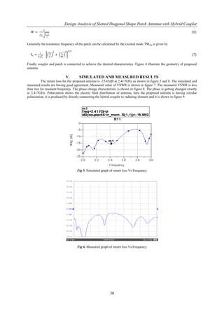
This document presents the design and analysis of a slotted diagonal shaped patch antenna with a hybrid coupler. Theoretical performance is analyzed using ADS software. Measured return loss is -15.65dB at 2.417GHz, agreeing with simulations. Circular polarization is achieved by directly connecting the hybrid coupler to the radiating element. The antenna has a gain of 3.319dB and directivity of 6.98dB, making it useful for wireless applications.