Download to read offline
![Khalid Hati, Abdellah El Hajjaji, Mourad Hati / International Journal of Engineering
Research and Applications (IJERA) ISSN: 2248-9622 www.ijera.com
Vol. 3, Issue 1, January -February 2013, pp.1335-1337
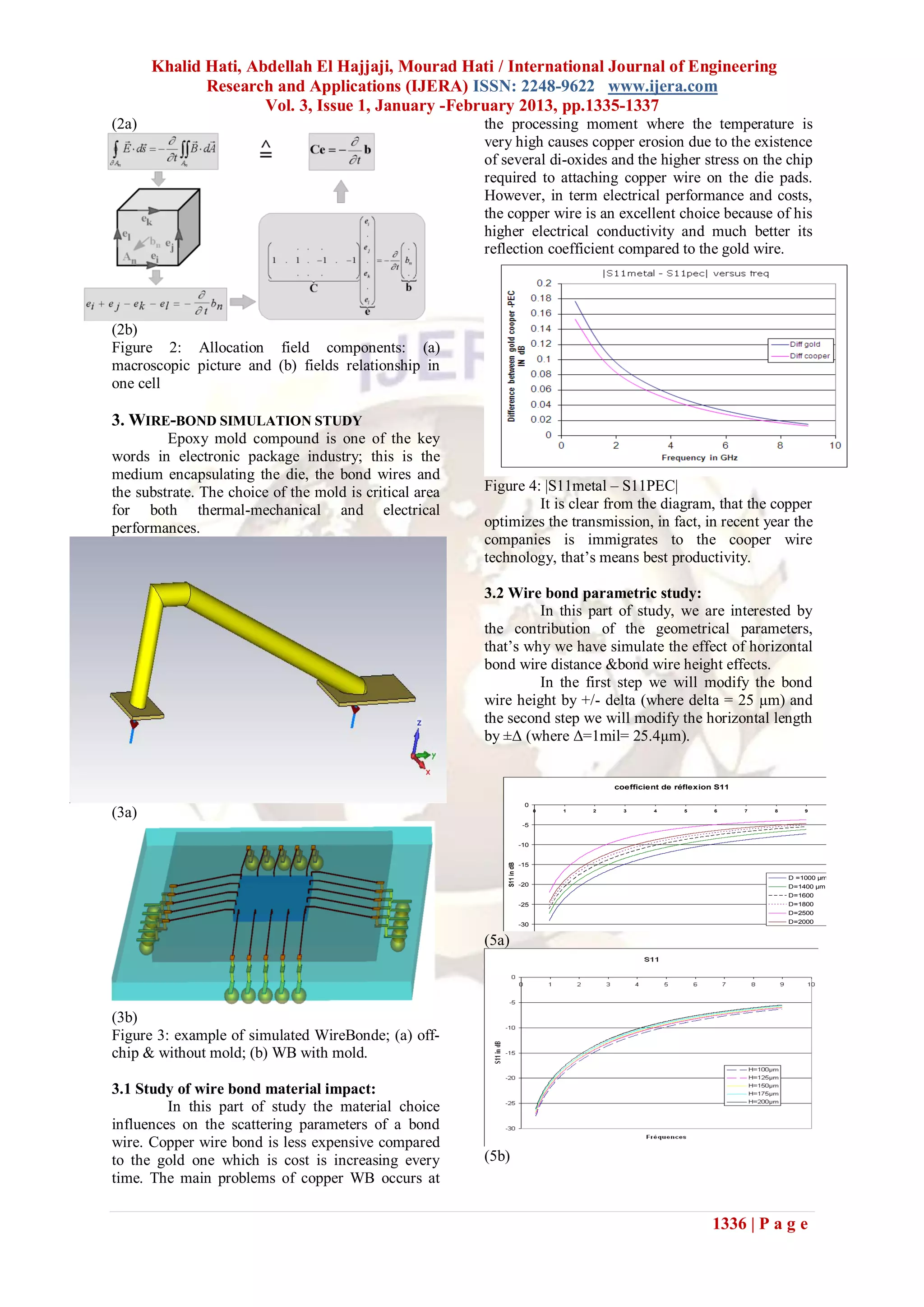
Figure 5 : S11 versus frequencies: (a) for different as capacitance and inductance, for arbitrarily shaped
distances;(b) for different height. objects are presented, which provide a direct link
Fig.5 illustrates the results of horizontal distance between design parameters and electrical
and height variations effect on the return loss performance. An approach using 3D modeling of
parameter. It has been shown that return loss the geometry for bonding wires for RF applications
increases versus frequency when the total length and packages is demonstrated.
increases (the sum of BW height, horizontal length
and oblique length), or Manhattan length. As result ACKNOWLEDGEMENTS
and suggestion, It is preferable to use the shorter The authors would like to thank Dr.
bond wire length in the interconnection, this why Natasha Healey from TDCmicroelectronics.
manufacturer has immigrated to the flip chip Appreciation is also extended to technical support
technology. from colleagues: Ms. Andronic. The authors would
also like to add a special thanks to Pr.A. El
3.4 Processing error Khamlichi and also Dr. M. Aoutoul.
Through this part, we are going to present
the result of study of the side effect of processing REFERENCES
error of bond wire. In fact, The fabrication process [1] David M. Pozard, Microwave engineering,
is not perfect, the position of a BW is not exact as it 3rd Ed, John Wiley & Sons, 2005.
was expected, then an error evaluation of the [2] J.O. Hallquist, LS-DYNA User’s Manual-
difference in return loss between theoretical and Version 940, Livermore Software
practical bond wire positions is simulated to know Technology Corporation, June 1997.
how much it is the impact on. [3] C.Guiffaut. Contribution à la method
FDTD pour l’étude d’antennes et de la
Position effect diffraction d’objets enfouis. Thèse de
doctorat d’université. Rennes : Université
0.9
0.8
de Rennes, 2005, 1, 200,220p.
0.7 [4] K .S. Yee. Numerical Solution of initial
Difference in dB
0.6 boundary value problems involving
0.5 -delta Maxwell. IEEE, transaction Antennas and
0.4 +delta
0.3 Propagation, Vol, 14, 1996,p 302-307.
0.2 [5] Lau JH, editor. Ball grid array technology.
0.1 McGraw-Hill; 1995. p. 396.
0
0 2 4 6 8 10
Frequencies in GHz
Figure 6: comparison of S11 difference between
Theo. & longer height and between Theo. & shorter
height.
As shown in fig.6, in the case of « +Δ »
that means the length of the wire is longer there are
more reflections of power.
From these results, we note that there is an
effect, in the case of position effect, the error
approximately equal to ± 0.8dB, and ± 0.3dB in the
case of the height effect.
4. CONCLUSION
This work starts with geometry modeling
for both on-chip and off-chip interconnects followed
by extensive electrical performance investigation.
During our work we have focused on the
return loss parameter because it is characterizes
essentially any two ports structure- the bond wire is
one of them- a lower return loss parameter values
means better values for transmission coefficient if
there are no conduction or dielectric losses. In
addition, the effect of geometrical and processing
error was analyzed
Design insight and suitable guidelines for
minimizing interconnect inductance are in phase of
investigation, electrical parameter extraction, such
1337 | P a g e](https://image.slidesharecdn.com/gx3113351337-130226000139-phpapp01/75/Gx3113351337-3-2048.jpg)

This document summarizes a study on electromagnetic modeling of electronic package wirebonds. It describes how the finite integration technique was used to simulate different wirebond geometries and materials. Key findings include: 1) Copper wirebonds performed better than gold in terms of transmission and reflection coefficient. 2) Increasing the total wirebond length (height + horizontal length) worsened the return loss. Shorter lengths were preferable. 3) Variations in wirebond height and position due to processing errors could cause up to 0.8dB difference in return loss between theoretical and actual positions.


![Available online at [www.ijeete.com]EFFECT OF DISPERSION AND FIBER LENGTH ON ...](https://cdn.slidesharecdn.com/ss_thumbnails/ij-v02-1516-e171-160112094437-thumbnail.jpg?width=640&height=640&fit=bounds)


