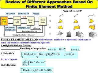
This document provides an outline for a thesis on analyzing transverse electric (TE) modes of rectangular hollow waveguides using the finite element method. It includes sections on reviewing different finite element approaches, introducing waveguides and electromagnetic field configurations within waveguides, developing the finite element formulation, providing an example analysis of a homogeneous hollow waveguide, comparing finite element results to analytical solutions, and plans for future work and references. The goal is to use the finite element method to calculate the propagation constant of TE modes in rectangular hollow waveguides and validate the approach against exact solutions.
Polarization insensitive switchable metamaterial absorber/reflector for X-ban...journalBEEI
A unit cell of squared shaped polarization-insensitive switchable metamaterial absorber/reflector is presented. The structure operates at 10.20 GHz under both absorber mode and reflector mode configurations. Copper wire bridging the gaps to form a circular shape structure were used as switches for operation mode selections. The structure was designed on an FR4 substrate, and the incidental wave angles were varied from 0 to 50 degrees. The structure demonstrated almost 100% absorption at resonance, 3.314 GHz percentage bandwidth at 80% as an absorber. On the other hand, as reflector, it demonstrated almost a 90% reflection and a usable bandwidth of 3.327 GHz.
International Journal of Engineering Research and Development is an international premier peer reviewed open access engineering and technology journal promoting the discovery, innovation, advancement and dissemination of basic and transitional knowledge in engineering, technology and related disciplines.
We follow "Rigorous Publication" model - means that all articles appear on IJERD after full appraisal, effectiveness, legitimacy and reliability of research content. International Journal of Engineering Research and Development publishes papers online as well as provide hard copy of Journal to authors after publication of paper. It is intended to serve as a forum for researchers, practitioners and developers to exchange ideas and results for the advancement of Engineering & Technology.
Modelling Optical Waveguide Bends by the Method of LinesTELKOMNIKA JOURNAL
A rigorous analytical and semi analytical method of lines has been used to calculate the
transverse-electric field attenuation coefficient of guided mode as it travels in waveguide bends structure.
Both approaches then were compared to get a better understanding on how the attenuation behaves along
single curve waveguides with constant radius of curvature. The Helmholtz Equation in polar coordinate
was transformed into a curvalinier coordinate to simulate the waveguide bends using the method of line
analysis. The simple absorption boundary conditions are used into the method of lines to demonstrate
evanescent field of the guided mode nature as its travels in waveguide bends structures. The results show
that a reasonable agreement between both theoretical approaches.
COMPACT DUAL-BAND BANDPASS FILTER BASED ON STUB-LOADED RECTANGULAR LOOP STEPP...ijeljournal
This work presents a compact dual-band bandpass filter (BPF) based on stub-loaded rectangular loop
stepped impedance resonator (SLRLSIR). The proposed SLRLSIR consists of two outer open-circuited and
two inner open-circuited stubs, which are designed to the central sides of the rectangular loop resonator.
Owing to its symmetry, even-and odd-mode analysis methods are applied to deduce the equivalent-circuit
equations and to justify the structural design. The second passband can be easily tuned by changing the two
inner open-circuited stubs when the first passband is fixed at a desirable frequency. The upper stopband is
improved by a pair of additional open-circuited stubs stepped impedance resonators at the I/O ports.
Transmission zeros are generated between passbands and stopbands. A SLRLSIR prototype dual-band BPF
with central frequencies of 2.42/4 GHz is fabricated and systematically studied. The measurement results
agreed well with the simulation results.
Bending and free vibration analysis of isotropic and composite beamsSayan Batabyal
The report mainly deals with the bending and free vibration analysis of beams using Finite Element Analysis. Softwares like ANSYS has been used and related theory discussed alongwith.
Application of Bio-Inspired Optimization Technique for Finding the Optimal se...IDES Editor
In this paper the maximum sidelobe level (SLL) reductions
of three-ring concentric circular antenna arrays
(CCAA) without and with central element feeding are examined
using two different classes of evolutionary optimization
techniques to finally determine the global optimal three-ring
CCAA design. Apart from physical construction of a CCAA,
one may broadly classify its design into two major categories:
uniformly excited arrays and non-uniformly excited arrays.
The present paper assumes non-uniform excitations and uniform
spacing of excitation elements in each three-ring CCAA
design and a design goal of maximizing SLL reduction associated
with optimal beam patterns and beam widths. The design
problem is modeled as an optimization problem for each CCAA
design. Binary coded Genetic Algorithm (BGA) and Bacteria
Foraging Optimization (BFO) are used to determine an optimum
set of normalized excitation weights for CCAA elements,
which, when incorporated, results in a radiation pattern with
optimal (maximum) SLL reduction. Among the various CCAA
designs the three-ring CCAA containing (N1=4, N2=6, N3=8)
elements along with central element feeding proves to be global
optimal design. BFO yields global minimum SLL (-34.18
dB) and global minimum BWFN (81.50) for the optimal design.
Analysis, Design and Optimization of Multilayer Antenna Using Wave Concept It...journalBEEI
The wave concept iterative process is a procedure used for analyses a planar circuits This method consists in generating a recursive relationship between a wave source and reflected waves from the discontinuity plane which is divided into cells. A high computational speed has been achieved by using Fast Modal Transform (FMT). In this paper we study a patch antenna and multilayer circuits, to determine the electromagnetic characteristics of these structures.
NS2 installation guideline for the student to install the software . It use for student to install and download the software. The software is about the experimental of communication technology.
IOSR Journal of Electronics and Communication Engineering(IOSR-JECE) is an open access international journal that provides rapid publication (within a month) of articles in all areas of electronics and communication engineering and its applications. The journal welcomes publications of high quality papers on theoretical developments and practical applications in electronics and communication engineering. Original research papers, state-of-the-art reviews, and high quality technical notes are invited for publications.
Dynamic design and simulation analysis of permanent magnet motor in different...Mellah Hacene
This paper deals with investigation on non purely sinusoidal input supply analysis of line-start PMM using finite element analysis (FEA), in the present times a greater awareness is generated by the problems of harmonic voltages and currents produced by non-linear loads like the power electronic converters. These combine with non-linear nature of PMM core and produce severe distortions in voltages and currents and increase the power loss, additional copper losses due to harmonic currents, increased core losses, electromagnetic interference with communication circuits, efficiency reduction, increased in motors temperature and torque oscillations. In addition to the operation of PMM on the sinusoidal supplies, the harmonic behavior becomes important as the size and rating of the PMM increases. Thus the study of harmonics is of great practical significance in the operation of PMM.
Analysis and Characterization of Different Comparator TopologiesAalay Kapadia
Comparator is one of the most important analog circuits required in many analog integrated circuits. It is used for the comparison between two different or same electrical signals. The design of Comparator becomes an important issue when technology is scaled down. Due to the non-linear behavior of threshold voltage (VT) when technology is scaled down, performance of Comparator is affected. Many versions of comparator are proposed to achieve desirable output in sub-micron and deep sub-micron technologies. The selection of particular topology is dependent upon the requirements and application. In this paper, we have shown the implementation of different topologies in 0.5 μm technology using the Mentor Graphics Tool. We have done the pre-layout simulation of two different topologies. We have performed DC, AC and transient analysis. We have also calculated output impedance. We have prepared a comparative analysis about them.
Convergence Behaviour of Newton-Raphson Method in Node- and Loop-Based Non-li...balaganesh boomiraja
A simplified Jacobian is derived for both node- and loop-based magnetic equivalent circuit analysis. The partial derivative term is eliminated in this simplified Jacobian using differential relative permeability. The convergence behaviour of the Newton-Raphson method is studied. The loop analysis exhibits more stable convergence than that of the node analysis while solving non-linear magnetic equivalent circuit using the Newton-Raphson method.
IRJET-Finite Element Analysis of Glazed SurfaceIRJET Journal
Raghunath .D. Deshpande, Gayatri Chiniwal, Laxmi Golsangi, "Finite Element Analysis of Glazed Surface", International Research Journal of Engineering and Technology (IRJET), Vol2,issue-01 March 2015. e-ISSN:2395-0056, p-ISSN:2395-0072. www.irjet.net
Abstract
In the present work finite element analysis of a glazed surface of a structure is performed. Considering particular location, topography and terrain and considering glass panel of a particular type, size and thickness, analysis is performed for wind pressure and suction acting on the surface. Different cases are considered – (i) varying truss widths, (ii) varying cable position and (iii) varying number of cables. The results of this work show that displacement, stress and weight of the steel of structure vary linearly with the variation in truss width. Displacement is found to be least for a certain range of truss width. Stresses decrease with increase in truss width and the weight of steel increases with increase in truss width. Having known this, one can choose economical and efficient steel supporting structure to support the glazing.
Analysis Of 3C-Sic Double Implanted MOSFET With Gaussian Profile Doping In Th...IJRES Journal
The present work aims at the design of 3C-SiC Double Implanted Metal Oxide Semiconductor Field Effect Transistor (DIMOSFET) with Gaussian doping profile in drift region for high breakdown voltages. By varying the device height ‘h’, function constant m and peak concentration 𝑁0, analysis has been done for an optimum profile for high breakdown voltage. With Gaussian profile peak concentration 𝑁0 = 1016 𝑐𝑚−3 at drain end and m as 1.496 ×10⁻²cm, highest breakdown voltage of 6.84kV has been estimated with device height of 200μm.
Présentation de la Recommandation CST RT017 Réunion SPSP 26102011FICAM
Voici une présentation pédagogique des enjeux de la nouvelle Recommandation CST RT017, de son calendrier et des changements techniques qu'elle occasionne.
Etude, conception et réalisation d'une antenne planaire HF en technologie mic...Ghassen Chaieb
Dans le cadre du mini projet en dispositifs micro-ondes et antennes, nous avons eu l'occasion
d'étudier une antenne planaire qui est constituée d’un plan de masse et d’un substrat
diélectrique dont la surface porte un ou plusieurs éléments métallisés appelés «Patch». Ces
Patchs peuvent prendre des formes différentes: carré, rectangulaire, disque. L’élément
rayonnant utilisé dans notre étude, est celui de forme rectangulaire, ses dimensions sont la
longueur L et la largeur W. Ces dimensions consistent à faire une adaptation d'impédance entre
le « Patch » est le milieu de rayonnement (l'air). L’alimentation de cet élément s’effectue au
moyen d’une ligne micro ruban reliée à un connecteur
La technologie Ultra Large Bande exige des largeurs de bande de fonctionnement jusqu'
à 100% plus grandes que la fréquence centrale de la bande passante. La transmission et la
réception réussies d'une impulsion ultra large bande qui occupe le spectre entier de 3,1 à 10,6
GHz.
L’objectif de ce mémoire est initialement la conception des antennes monopoles
planaires possédant une très large bande passante avec un profil physiquement compact et
planaire s'approche du modèle de rayonnement omnidirectionnel.
Les antennes monopoles de formes de patchs triangulaire, elliptique et losange qui sont
alimentées par un guide d’onde coplanaire ont été simulées à l’aide du logiciel CST
Microwave Studio. Une étude de l’influence des différents éléments constituant l’antenne
triangulaire est également faite. Les résultats de simulation obtenus sont présentés et discutés.
Mots clés : L’antenne ultra large bande, Antenne monopole triangulaire, Antenne monopole
elliptique, Antenne monopole losange, CST Microwave Studio, Adaptation, Résultats
Radioélectriques.
Ultra Wideband technology requires operating bandwidths up to 100% greater than the
center frequency of the bandwidth.
The successful transmission and reception of an ultra wideband impulse that occupies
the entire spectrum from 3.1 to 10.6 GHz.The objective of this memory is initially the design
of the planar monopole antennas having a very broad bandwidth with a physically compact
profile and Planar approaches the omnidirectional radiation pattern.
The monopole antennas of triangular, elliptical and diamond patchsforms which are fed
by a coplanar waveguide were simulated using CST Microwave Studio software. The
influence of the various elements constituting the triangular antenna is also made. The
simulation results are presented and discussed.
Radiation patterns account of a circular microstrip antenna loaded two annularwailGodaymi1
In this paper, theoretical study of circular microstrip antenna loaded two annular (CMSAL2AR) and calculation
of the radiation pattern using principle equivalence with moment of method formulation of electromagnetic
radiation in this these based on the bodies of revolution (BoR), which are generated by revolution a planar curve
about an axis called axis of symmetry to solving the electric fields integral equation (EFIE) and magnetic field
integral equation (MFIE). To find an unknown electric current density on the conductor surface ,and both
unknowns electric and magnetic density current on the dielectric surface which are responsible for the
generation of far fields radiation in the space for the components (Eθ ,Eφ) ,the surface currents was represented
by a set of basis functions that give the Fourier series because the body has a circular symmetry property and
then select a set of weighted functions to find a linear system by using Galerkin method which requires that the
weighted functions are equal to the complex conjugate of the current ( ) * W = J .from radiation pattern
calculated the Directive gain can be utilized to the directive gain increased to (G= 21.30 dB) when
( 0.015λ 1 = g R ) for the ratio of (Rab= 5.5), and bandwidth has been better (BW%= 19.9%) when
( 0.01λ 1 = g R ) for the ratio (Rab= 6.5) .
A New Two-Dimensional Analytical Model of Small Geometry GaAs MESFETIJMERJOURNAL
ABSTRACT : In this paper, a simple and exact analytical model for Small Geometry GaAs MESFET is developed to determine the potential distribution along the channel of the device. The model is based on the exact solution of two-dimensional Poisson’s equation in the depletion region under the gate. Then the obtained model is used to study the channel potential and threshold voltage of the device. Using the analytical model, the effect of the device parameter and bias conditions on performance of the device is investigated. The obtained results are graphically exhibited and discussed. In order to verification of the analytical results, TCAD device simulator is used and good accordance is observed.
R,L,C, G parameters of a co-axial & 2-wire transmission line
Field solutions for TE and TM modes for a waveguide
Design and analysis of rectangular waveguide to support TE10 mode
Design and analysis of circular waveguide to support TE11 mode
Dynamic stiffness and eigenvalues of nonlocal nano beams - new methods for dynamic analysis of nano-scale structures. This lecture gives a review and proposed new techniques.
Optimization of Surface Impedance for Reducing Surface Waves between AntennasIJMER
International Journal of Modern Engineering Research (IJMER) is Peer reviewed, online Journal. It serves as an international archival forum of scholarly research related to engineering and science education.
TWO DIMENSIONAL MODELING OF NONUNIFORMLY DOPED MESFET UNDER ILLUMINATIONVLSICS Design
A two dimensional numerical model of an optically gated GaAs MESFET with non uniform channel doping has been developed. This is done to characterize the device as a photo detector. First photo induced voltage (Vop) at the Schottky gate is calculated for estimating the channel profile. Then Poisson’s equation for the device is solved numerically under dark and illumination condition. The paper aims at developing the MESFET 2-D model under illumination using Monte Carlo Finite Difference method. The results discuss about the optical potential developed in the device, variation of channel potential under different biasing and illumination and also about electric fields along X and Y directions. The Cgs under different illumination is also calculated. It has been observed from the results that the characteristics of the device are strongly influenced by the incident optical illumination.
COMPARATIVE STUDY ON BENDING LOSS BETWEEN DIFFERENT S-SHAPED WAVEGUIDE BENDS ...cscpconf
Bending loss in the waveguide as well as the leakage losses and absorption losses along with a comparative study among different types of S-shaped bend structures has been computed with
the help of a simple matrix method.This method needs simple 2×2 matrix multiplication. The
effective-index profile of the bended waveguide is then transformed to an equivalent straight
waveguide with the help of a suitable mapping technique and is partitioned into large number of thin sections of different refractive indices. The transfer matrix of the two adjacent layers will be a 2×2 matrix relating the field components in adjacent layers. The total transfer matrix is
obtained through multiplication of all these transfer matrices. The excitation efficiency of the
wave in the guiding layer shows a Lorentzian profile. The power attenuation coefficient of the
bent waveguide is the full-width-half-maximum (FWHM) of this peak .Now the transition losses and pure bending losses can be computed from these FWHM datas.The computation technique
is quite fast and it is applicable for any waveguide having different parameters and wavelength of light for both polarizations(TE and TM)
2137ad Merindol Colony Interiors where refugee try to build a seemengly norm...luforfor
This are the interiors of the Merindol Colony in 2137ad after the Climate Change Collapse and the Apocalipse Wars. Merindol is a small Colony in the Italian Alps where there are around 4000 humans. The Colony values mainly around meritocracy and selection by effort.
Hadj Ounis's most notable work is his sculpture titled "Metamorphosis." This piece showcases Ounis's mastery of form and texture, as he seamlessly combines metal and wood to create a dynamic and visually striking composition. The juxtaposition of the two materials creates a sense of tension and harmony, inviting viewers to contemplate the relationship between nature and industry.
Explore the multifaceted world of Muntadher Saleh, an Iraqi polymath renowned for his expertise in visual art, writing, design, and pharmacy. This SlideShare delves into his innovative contributions across various disciplines, showcasing his unique ability to blend traditional themes with modern aesthetics. Learn about his impactful artworks, thought-provoking literary pieces, and his vision as a Neo-Pop artist dedicated to raising awareness about Iraq's cultural heritage. Discover why Muntadher Saleh is celebrated as "The Last Polymath" and how his multidisciplinary talents continue to inspire and influence.
2137ad - Characters that live in Merindol and are at the center of main storiesluforfor
Kurgan is a russian expatriate that is secretly in love with Sonia Contado. Henry is a british soldier that took refuge in Merindol Colony in 2137ad. He is the lover of Sonia Contado.
1. by
Anuj
14/MAP/0012
M.Sc. (Applied Physics)
Under the guidance of
Dr. Manmohan Singh Shishodia
Gautam Buddha University, Greater Noida (U.P.)
Finite Element Method for Analyzing TE
Modes of Rectangular Hollow Waveguide
2. Outlines
Review of Different Approaches Based On Finite Element
Method
Introduction To Waveguide
EM Field Configuration Within The Waveguide
FEM Formulation
Homogeneous Hollow waveguide Example
MATLAB Code To Calculate Propagation Constant
Result and comparison b/w FEM and Analytical Results
Overall Summary
Future Plan
References
3.
4. Review of Different Approaches Based On
Finite Element Method
FINITE ELEMENT METHOD: finite element method is a numerical technique to
solve the ordinary/partial differential equation.
1.Weighted Residual Method
Boundary value problem
i. Galerkin’s
ii. Least Square
iii. Collocation
‘types of element’
R
j
R
j njdguLd )1(1,0)(Re
0Re2
d
Ai
b
a
i nidxxx )1(1,0)(Re
SDgLu ,
_
Re uL
5. 0.0 0.2 0.4 0.6 0.8 1.0
-0.008
-0.004
0.000
0.004
0.008
0.012
(yT/WL
2
)
x/L
Galerkin
Least Square
Collocation
ERROR PLOT FOR DIFFERENT APPROACHES
0.0 0.2 0.4 0.6 0.8 1.0
-0.30
-0.25
-0.20
-0.15
-0.10
-0.05
0.00
0.05
Solutions obtained from different methods
(yT/WL
2
)
x/L
Exact, Collocation
Galerkin, Least Square
Review of Different Approaches Based On
Finite Element Method
0)(2
2
xw
dx
yd
T
032
2
W
dx
yd
T
2
0
L
xfor
02
2
W
dx
yd
T Lx
L
for
2
* Hence the plot shown that the eroor is least in the Galerkin’s approach.
6. Introduction To Waveguide
A Hollow metallic tube of uniform cross section for transmitting electromagnetic waves
by successive reflections from the inner walls of the tube is called waveguide.
It may be used to carry energy over longer distances to carry transmitter power to an
antenna or microwave signals from an antenna to a receiver.
Waveguides are made from copper, aluminum or brass. These metals are extruded into
long rectangular or circular pipes.
The electric and magnetic fields associated with the signal bounce off the inside walls
back and forth as it progresses down the waveguide.
*Fig. Three-dimensional view of the electric field for the TE₁₀– mode in a
rectangular waveguide
*http://www.radartutorial.eu/03.linetheory/Waveguides.en.html
7. EM Field Configuration Within The Waveguide
In order to determine the EM field configuration within the waveguide, Maxwell’s
equations should be solved subject to appropriate boundary conditions at the walls of the
guide.
Such solutions give rise to a number of field configurations. Each configuration is known
as a mode.
02
2
2
2
2
z
zz
Ek
y
E
x
E
022
EkE
ck 22
)()(),( yYxXyxEz
t
B
EE
,0
t
E
c
BB
2
1
0
02
2
2
2
2
2
zEk
cyx
xkBxkAxX xx cossin
02
2
2
2
2
2
XYk
cdy
Yd
X
dx
Xd
Y
bnaxmEEz /cos/cos0
22
22
/
b
n
a
m
ck
mn
b
n
a
m
c
22
Scalar Wave Equation
Where
Maxwell’s Equations
*David J. Griffiths, “Introduction to Electrodynamics” Pearson Education, Inc., ISBN-978-81-203-1601-0 (1999),.
8. Possible Types of modes
Transverse Electromagnetic (TEM):
Here both electric and magnetic fields are directed
components. (i.e.) E z = 0 and Hz = 0
Transverse Electric (TE) wave:
Here only the electric field is purely transverse to the direction of propagation and
the magnetic field is not purely transverse. (i.e.) E z = 0, Hz ≠ 0.
Transverse Magnetic (TM) wave:
Here only magnetic field is transverse to the direction of propagation and the electric
field is not purely transverse. (i.e.) E z ≠ 0, Hz = 0.
Dimensions of the waveguide which determines the
operating frequency range
EM Field Configuration Within The Waveguide
mnbnamc
22
//
Where is the cutoff frequency
9. The size of the waveguide determines its operating frequency range.
The frequency of operation is determined by the dimension ‘a’ and b.
This dimension is usually made equal to one – half the wavelength at the
lowest frequency of operation, this frequency is known as the waveguide cutoff
frequency.
At the cutoff frequency and below, the waveguide will not transmit energy. At
frequencies above the cutoff frequency, the waveguide will propagate energy.
Angle of incidence(A) Angle of reflection (B)
(A = B)
(a)At high frequency
(b) At medium frequency
( c ) At low frequency
(d) At cutoff frequency
EM Field Configuration Within The Waveguide
10. 022
k
dsk
yx
F
s
22
22
2
1
)(
,
22
0
2
zr kkk
0
0
2
k
dSk
yx
F e
ee
N
e A
e
e
22
22
2
1
2
22 ,
e
yx
3
33 ,
e
yx
11
1
, yx
e
yxP ,
x
y
Element e
1
2 3
cybxae
FEM Formulation
The scalar wave equation for a homogeneous isotropic medium is chosen.
The scalar wave equation has many applications.
It can be used to analyse problem such as the propagation of plane waves.
It can be used to analyse the TE and TM modes in waveguides/weakly guiding optical
fibers.
The FEM solution of the above scalar equation by minimisation of a corresponding
functional is given by
The function at a point inside the triangle may be
approximated as , the linear terms:-
e
Fig. A typical first order triangular element.
11. 111 cybxae 222 cybxae 333 cybxae
the solution of these equations gives
3
1
3
1
3
1 i
eii
i
eii
i
eii ccbbaa
c
b
a
yx
yx
yx
e
e
e
1
1
1
33
22
11
3
2
1
3
2
1
212113133232
123123
211332
2
1
e
e
e
xyyxxyyxxyyx
xxxxxx
yyyyyy
A
c
b
a
1
1
1
2
1
33
22
11
yx
yx
yx
A
FEM Formulation
where
……………………………………………..(1)
12. 23132132321
2
1
,
2
1
,
2
1
xx
A
cyy
A
bxyyx
A
a
31113213132
2
1
,
2
1
,
2
1
xx
A
cyy
A
bxyyx
A
a
12321321213
2
1
,
2
1
,
2
1
xx
A
cyy
A
bxyyx
A
a
Hence, we can write
ei
i
ie u
3
1
321 eeee 321 uuuu 321 bbbb 321 cccc
Using row vectors
dS
uukc
cbb
F
e
e
N
e A
t
e
tt
e
t
e
tt
e
t
e
tt
e
1 22
1
eN
e
t
eee
t
eee QkPF
1
2
2
1
FEM Formulation
eN
e
t
eee
t
eee QkPF
1
2
2
1 ccbbAP tt
ee
211
121
112
12
e
e
A
Q
Using eqn (1)
13. Homogeneous Hollow Waveguide Example
The example of a homogeneous hollow waveguide (WR-90) is taken to calculate the value of
propagation constant.[WR-90 waveguide :- frequency range:- 8.2GHz to 12.4GHz]
The dimensions of the waveguide is 2.286cm*1.016cm.
First we will dicretize the domain (waveguide) using “pde-toolbox” , this process is known as
meshing,.
Then we create three matrices....
1. For triangle node numbers:- A file element which has three node numbers of each triangle,
with rows arranged to correspond to triangle number in ascending order.
2. Coordinates of nodes:- A file coord which has two columns containing x coordinate in the
first column and y coordinate in the second, with rows arranged to correspond to node
numbers in ascending order.
3. Boundary node numbers:- A file bn with one column containing the boundary node numbers
in ascending order.
14. function [pe,qe] = triangle1(x,y)
ae=x(2)*y(3)-x(3)*y(2)+x(1)*y(2)-x(2)*y(1)-x(1)*y(3)+x(3)*y(1);
ae=abs(ae)/2;
b=[y(2)-y(3),y(3)-y(1),y(1)-y(2)];
c=[x(3)-x(2),x(1)-x(3),x(2)-x(1)];
b=b/(2*ae);
c=c/(2*ae);
pe=(b.'*b+c.'*c)*ae;
qe=[2,1,1;1,2,1;1,1,2];
qe=qe*(ae/12);
end
MATLAB Code To Calculate Propagation Constant
Function
clc
clear all
format long g
% load the data file
element=xlsread('element.xlsx');
coord=xlsread('coord.xlsx');
bn=xlsread('bn.xlsx');
% find the total no. of elements and nodes
ne=length(element(:,1));
nn=length(coord(:,1));
% set up pull global matrices
pg=zeros(nn,nn);
qg=zeros(nn,nn);
% sum over triangles
for e=1:ne;
% Get the three node no. of triangle no. e
node=[element(e,:)];
% Get the coordinates of each node and form row vectors
x=[coord(node(1),1),coord(node(2),1),coord(node(3),1)];
y=[coord(node(1),2),coord(node(2),2),coord(node(3),2)];
% Calculate the local matrix for triangle no. e
[pe,qe]=triangle1(x,y);
% Add each element of the local matrix to the appropriate lement
of the
% global matrix
for k=1:3;
for m=1:3;
pg(node(k),node(m))=pg(node(k),node(m))+pe(k,m);
qg(node(k),node(m))=qg(node(k),node(m))+qe(k,m);
end
end
end
ksquare=eig(pg,qg)
Script
15. Result and comparison b/w FEM and Analytical
Results
No mode 9.5748
(9.56119)
38.4625
(38.24479)
1.8891
(1.8886)
11.4693
(11.4498)
40.3694
(40.1334)
7.5638
(7.5545)
17.159
(17.1157)
46.11235
(45.7993)
m
n
0
0
1
1
2
2
16. Overall Summary
Learned fundamentals of PDEs useful for scientists and engineers
(e.g., elliptic, parabolic & hyperbolic, scalar wave eqn).
Studied waveguide and learned its different fundamental mode i.e.
TE.
Calculated values of propagation constant for different modes.
17. Future Plan
In future, we will calculate the propagation constant for TM mode.
we will solve the problems on waveguide using ANSYS.
We will move towards optical wave guide and plasmonic waveguide
and study the different properties with the help of ANSYS .
18. 1. Erik G. Thompson, “An Introduction To The Finite Element Method”, John Willey &
Sons, ISBN: 978-81-265-2455-6 (2005)
2. Radhey S. Gupta, “Elements of Numerical Analysis”, Macmillan India Ltd.,ISBN: 446-
521 (2009),.
3. David J. Griffiths, “Introduction to Electrodynamics” Pearson Education, Inc., ISBN-
978-81-203-1601-0 (1999),.
References