The article discusses the use of a Static Synchronous Compensator (STATCOM) utilizing fuzzy logic control for enhancing voltage profiles in electrical distribution networks. The proposed system showed improved voltage stability and flexibility compared to conventional methods, effectively compensating for load voltage drops during both balanced and unbalanced load conditions. Simulation results indicated that the STATCOM could restore voltage to within 97% of the nominal value and increased stability margins by approximately 20%.
![International Journal of Electrical and Computer Engineering (IJECE)
Vol. 10, No. 4, August 2020, pp. 3367~3374
ISSN: 2088-8708, DOI: 10.11591/ijece.v10i4.pp3367-3374 3367
Journal homepage: http://ijece.iaescore.com/index.php/IJECE
Voltage profile enhancement in distribution network using
static synchronous compensator STATCOM
Mohammed Y. Suliman
Department of Technical Power Engineering, Technical College, Northern Technical University, Iraq
Article Info ABSTRACT
Article history:
Received Mar 9, 2019
Revised Jan 23, 2020
Accepted Feb 1, 2020
STATCOM is one of FACTS devices that used as regulator for transmission
and distribution systems which works for reactive power compensation.
STATCOM utilisation in distribution system mostly for enhancing the profile
of voltage, where used for adjusting the disturbance voltage by injecting into
the system a controllable voltage. This paper present a Fuzzy controller
based on STATCOM to enhance the voltage profile in distribution network.
The controller of STATCOM has simulated for different types of abnormal
load conditions of balance and unbalance load. The results of simulation
show ability of proposed design to enhance the load voltage which was 96%
of the nominal value.
Keywords:
D-q Theory
FACTS
Fuzzy logic
STATCOM
Vsc Copyright © 2020 Institute of Advanced Engineering and Science.
All rights reserved.
Corresponding Author:
Mohammed Y. Suliman,
Department of Technical Power Engineering,
Technical College, Northern Technical University,
Mosul, Iraq.
Email: mohammed.yahya@ntu.edu.iq
1. INTRODUCTION
STATCOM is one of the most important devices can be used in power flow control and power
quality, which permit a utilise function in the prepared in the manner that without any loss the performance
expectation. The equipments such as transformer, motor, computer, printer, equipment of communication and
all types of house machines. These equipments mentioned were affect to the quality of power negatively [1].
When a large load in the network the reactive power unable to be transmitted even though with essential
of buses voltage magnitude [2]. Voltage instability cause complete or partial discontinuation in the network.
The STATCOM advantage is that can regulate efficiently the injected current in to the bus [3].
Also STATCOM has several applications in compensation of the conditions of sag/swell, the Suppressing
in harmonics of line currents and improve the power factor in the load, and reactive power compensation
in transmission line also in the load also STATCOM mitigate the fluctuations of the bus voltage [4, 5].
STATCOM with storage energy is advisable for controlling the injected voltage in its magnitude and also
the angle by VSC "Voltage Source Converter” for controlling the powers "active and reactive"
of STATCOM [6]. Many works have been suggested for the implementation of voltage profile enhancement
in the literature. Improving Voltage Profile using PI Controller in [7]. Whereas [8] presents Optimal location
of UPFC to enhence voltage profile. In [9] presents Enhancement of voltage profile using SVC. The use of PI
controller in [7], has many drawbacks that needs tunning at each operating point, slow in response and less
smoother. The use of UPFC in [8], needs settings and controllers for both STATCOM and also for SSSC.
The use of SVC in [9], have passive parameters that affect to the tuning of the system and nake some
oscillation in response. The new porposed of STATCOM for voltage profile enhancement with Fuzzy logic
control is a high-speed response and smoother than conventional controller also the propsed system use VSC
instead of passive element in SVC. The use of d-q theory to calculate the reactive power and the bus voltage](https://image.slidesharecdn.com/v05191331feb23jan30mar19u-201211024115/85/Voltage-profile-enhancement-in-distribution-network-using-static-synchronous-compensator-STATCOM-1-320.jpg)
![ ISSN: 2088-8708
Int J Elec & Comp Eng, Vol. 10, No. 4, August 2020 : 3367 - 3374
3368
for compensation added another feature of small-time calculation of about one cycle compared with previous
works [7],[8] and[9] that takes more than one cycle for calculation the peak amplitude, and need more
peripherals design.
2. VOLTAGE REGULATION AND COMPENSATION
The shunt device connections for regulation of bus voltage are shown in Figure 1. The model
contains power transmission line, supply (Vs), and load where the injection was in the middle of the line.
Phasor diagram, shows that line current angle has relation with the load side, which means that the active
component of current (IC) is injects to enhance the line current (Isc) and then the load voltage. The device of
current source is used for compensating the load reactive component this done by inject or absorb current (IC)
to or from the network. This lead to enhance regulation of voltage and also reduced reactive component of
the source current. Figure 2 shows Q-V characteristics of STATCOM, where the inductive load requires
enough reactive current for appropriate working so, the source should be feeding it; and this will increase
the line current from the generating area. If the feeding of reactive power is near load area, the supply current
may be reduced thus improving the voltage regulation (load side) [10]. Three methods can improve
the regulation; first by using a bank of capacitor, by using VSI "voltage source inverter" or by using CSI
"current source inverter" [11]. The STATCOM provide voltage for supporting the system under huge
abnormal condition through that the bus voltage would be deviate from the compensator normal range [12].
The main advantage of the use of voltage source converter VSC that reactive power can be generate
(instead of using capacitors) independent to the line current [13]. The three phase inverter used in inject
the controllable voltage, many techniques of modulation wrer used to implement the VSC like SPWM
(sine PWM) or SVPWM (Space Vector PWM) [14]. In distribution system the STATCOM connected before
load as shown in Figure 3[15].
Figure 1. Principles of shunt compensation Figure 2. V-Q characteristics of STATCOM
Figure 3. STATCOM connection
L1L2
X/2 X/2
VcVs Vr
Isc Icr
Vs=Vc=Vr=V
Vs
Vc
Vr
Ic
IcrIsc δ/4 δ/4
QC (C Max)
Capacitive
QL (L Max)
Inductive
Q
V
0.1
0.2
0.3
0.4
0.5
0.6
0.7
0.8
0.9
1.0
Transient
0
Feeder
Line
Vs
Vi
is
L-CFilter
Vdc
VL
Load
Controller
v
i
i](https://image.slidesharecdn.com/v05191331feb23jan30mar19u-201211024115/85/Voltage-profile-enhancement-in-distribution-network-using-static-synchronous-compensator-STATCOM-2-320.jpg)
![Int J Elec & Comp Eng ISSN: 2088-8708
Voltage profile enhancement in distribution network using static synchronous … (Mohammed Y. Suliman)
3369
3. MEASURING THE REACTIVE POWER AND LINE VOLTAGE
For measuring reactive power and line voltage, d-q theory has been applied [16]. This theory valid
for time-domain “operation in transient or steady state”, and can be applied for different current and voltage
waveforms, this allowing to design controller in real time for reactive power [17]. Also the simple of
transformation calculations, and easy to separate the alternated value and mean value respectively [18].
This theory performs by transformations known “park transformation” from a stationary to rotating
coordinates “abc to dq” [19]. The applied of dq theory (i.e. va, vb and vc) is as follows:
[
vd
vq
v0
] =
2
3
[
cos(∅) cos( ∅ −
2π
3
) cos(∅ +
2π
3
)
−sin(∅) −sin(∅ −
2π
3
) −sin(∅ +
2π
3
)
1
2
1
2
1
2 ]
[
va
vb
vc
] (1)
[
id
iq
i0
] =
2
3
[
cos(∅) cos( ∅ −
2π
3
) cos(∅ +
2π
3
)
−sin(∅) −sin(∅ −
2π
3
) −sin(∅ +
2π
3
)
1
2
1
2
1
2 ]
[
ia
ib
ic
] (2)
∅ = (𝜔𝑡 + 𝜃) (3)
Where “ ∅ ” is phase angle between the fixed and rotating coordinates with respect to time and “θ” is angle
between voltage and current. The compensated active and reactive power:
𝑝 = 𝑉𝑑 𝐼 𝑑 + 𝑉𝑞 𝐼𝑞 (4)
𝑞 = 𝑉𝑑 𝐼𝑞 − 𝑉𝑞 𝐼 𝑑 (5)
The accumulated voltage is:
v = √vd
2 + vq
2 (6)
4. STATCOM CONTROL DESIGN
Figure 4 shows the control system block diagram of the STATCOM. The phase voltages are
measured and the signals enter low pass filter for eliminating high frequency component. The d-q
components in (1) and (2) are calculated using “park transformation”. The aggregated voltage then calculated
using (6) this voltage is a feedback to closed loop control system, where compared with the vref set point
reference voltage of the busbar then error signals will generate verorr.
Verror = V + Vref (7)
Figure 4. Block diagram of control system
5. FUZZY LOGIC CONTROL SYSTEMS
In this study FLC “Fuzzy logic controller” was used, FLC is adequate for systems that have
mathematical model is not easy to derive [20]. Takagi-Sugeno inference mechanism systems is applied in this
study [21]. Artificial Neural Network (ANN) is used for tuning the MFs “membership functions” of
the Takagi-Sugeno [22]. The fuzzy logic control with capabilities of using the adaptive learning of ANN,
Phase Locked
Loop
va
vb
vc
vd
vq
2 2
Park
Transformation
abc to d-q
Low Pass
Filter √Vd+Vq Σ
v
Vref
Fuzzy Logic
Controller
Vmax
Vmin
VSTATCOM
Verror
Ф](https://image.slidesharecdn.com/v05191331feb23jan30mar19u-201211024115/85/Voltage-profile-enhancement-in-distribution-network-using-static-synchronous-compensator-STATCOM-3-320.jpg)
![ ISSN: 2088-8708
Int J Elec & Comp Eng, Vol. 10, No. 4, August 2020 : 3367 - 3374
3370
from this approach trained can be more easy also the rule base of Fuzzy is reduced [23]. The Fuzzy control
system constructed of 5-layers, two types of parameters in each layer some of them needs tuning other not
during step of training [24]. The details of emulating fuzzy logic control design steps for five layers output is
given in reference [25]. The two inputs universe of discourse are divide into 7 triangle MFs and
the overlap between them of 50%, the input to the controller is error and Δerror, so that for 7 MFs,
49-control rules resultant of linear functions that required to determine as shown in Figure 5a and b. To tune
these rules using ANN, 2-groups of data are used. Also 2- vectors of input: Verror and ΔVerror the output is
modulation index "m".
(a)
(b)
Figure 5. Fuzzy logic design (a) structure (b) the surface
6. SIMULATION STUDY
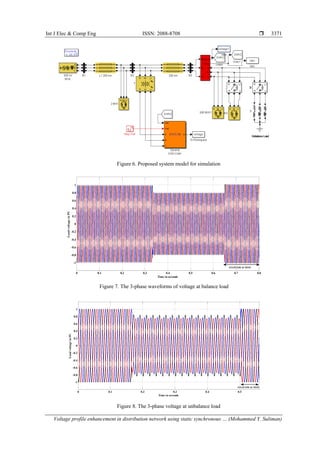
Study model contain feeder and changeable load of 2- load branches for balance condition and
additional load for unbalance condition as shown in Figure 6. The STATCOM in load side for compensating
the load voltage. Test the model start by load changing and continues measure the voltage at load bus
the compensation done at t=0.65 seconds for balance load as shown in Figure 7. The result shows the load
voltage drop increased proportionally as load increase, drop was maximum (0.8 pu) occur between 0.33 and
0.65 sec respectivily. Figure 8 shows the results for unbalance load action to compensate the load voltage for
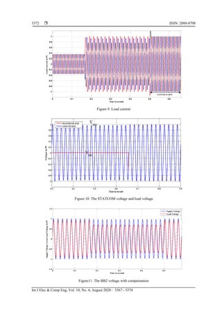
unbalance condition the STATCOM mitigate and restored the load voltage drop at 0.5 seconds. Figure 9
shows the load current before and after compensation, this compensation process done by injecting voltage
VSTATCOM where phase voltage as a reference as shown in Figures 10 and 11 respectively. The FFT analysis
of the voltage of bus BB3 is shown in Figure 12, the total harmonic distorsion THD was 0.22% after injects
VSTATCOM. The power-voltage characteristic at load bus shown in Figure 13, from results can note that
the load voltage enhanced the amplitude with STATCOM and also stability margin increased.](https://image.slidesharecdn.com/v05191331feb23jan30mar19u-201211024115/85/Voltage-profile-enhancement-in-distribution-network-using-static-synchronous-compensator-STATCOM-4-320.jpg)
![Int J Elec & Comp Eng ISSN: 2088-8708
Voltage profile enhancement in distribution network using static synchronous … (Mohammed Y. Suliman)
3373
Figure 12. The FFT analysis of the voltage of BB3
Figure 13. P-V curve
7. CONCLUSION
In this study, a STATCOM based Fuzzy logic control has been installed in load side, two cases of
disturbance conditions have been studied using MATLAB simulation the increase in load in balance and
unbalance. Results shown the compensation system with Fuzzy controller enhance the load voltage also
increase the stability margin about 20%. The simulation compared before and after inject compensation
voltage was studied for two types of load balance and unbalance condition. In two conditions the STATCOM
ability to restore the voltage of the load to the nominal value (within 97%). The use of STATCOM in
compensation more flexible and simple in design the controller and also not affect to the netwok parameters
as in [7], [8] respectively. Also fast response of design compensation system due to small computation time
compared with and [9], this important for implementation in real time.
REFERENCES
[1] E. Acha, C. Fuerte, H. Ambriz and C. Angeles-Camacho, "FACTS Modeling and Simulation in Power Networks",
John Wiley & Sons Ltd, pp 21-23, 2004.
[2] P. Kumar, “Enhancement of power quality by an application FACTS devices,” International Journal of Power
Electronics and Drive Systems (IJPEDS), vol.6, no. 1, pp. 10-17, 2015.
[3] A. Oukennou, et al., “Coordinated Placement and Setting of FACTS in Electrical Networks based on
eqKalai-smorodinsky Bargaining Solution and Voltage Deviation Index,” International Journal of Electrical
andomputer Engineering (IJECE), vol. 6, no. 6, pp 4079-4088, 2018.
[4] R. Mathur and R. Varma, "Thyristor-based FACTS Controllers for Electrical Transmission Systems," Wiley-IEEE
Press Power engineering, Piscataway, NJ, Mar, pp 34-36, 2002.
1 1.5 2 2.5 3 3.5
0
0.2
0.4
0.6
0.8
1
1.2
Load Power in PU
LoadvoltageinPU
With Statcom
Without Statcom](https://image.slidesharecdn.com/v05191331feb23jan30mar19u-201211024115/85/Voltage-profile-enhancement-in-distribution-network-using-static-synchronous-compensator-STATCOM-7-320.jpg)
![ ISSN: 2088-8708
Int J Elec & Comp Eng, Vol. 10, No. 4, August 2020 : 3367 - 3374
3374
[5] Hingorani and L. Gyugyi, "Understanding FACTS, Concepts and technology of flexible AC transmission systems,"
IEEE Press, pp 172-174, 2000.
[6] B. Yang, G. Zeng,Y. Zhong and Z. Su, "Cascade STATCOM step wave optimization based on PSO," IEEE
International Power Electronics and Application Conference and Exposition, pp1445-1450, shanghai, china, 2014.
[7] S. H. Qazi and M. W. Mustafa, "Improving Voltage Profile of Islanded Microgrid using PI Controller,"
International Journal of Electrical and Computer Engineering (IJECE), vol. 8, no. 3, pp 1383-1388, 2018.
[8] S. Hocine and L. Djamel, "Optimal number and location of UPFC devices to enhence voltage profile and
minimizing losses in electrical power systems", International Journal of Electrical and Computer Engineering
(IJECE), vol.9, no.5, pp 3981-3992, 2019.
[9] B. Singh and G. Agrawal, "Enhancement of voltage profile by incorporation of SVC in power system networks by
using optimal load flow method in MATLAB/Simulink environments", Energy Reports, Elseier, vol 4,
pp 528-535, 2018.
[10] Anulal A.M, A. Mohan and Lathika B.S, "Reactive power compensation of wind-diesel hybrid system using
STATCOM with Fuzzy tuned and ANFIS tuned PID controllers", International Conference on Control
Communication & Computing India (ICCC), pp. 325-330, Trivandrum, 2015.
[11] Hailian Xie, Angquist Lennart, and Hans Peter Nee, "Investigation of Statcoms with Capacitive Energy Storage for
Reduction of Voltage Phase Jumps in Weak Networks,", IEEE trans. on power systems, Vol. 24, No. 1, FEB. 2009.
[12] R. Vanitilaand M. Sudhakaran, "Differential Evolution algorithm based Weighted Additive FGA approach for
optimal power flow using muti-type FACTS devices", Emerging Trends in Electrical Engineering and Energy
Management Conference(ICETEEEM), Chennai, pp. 198-204, 2012.
[13] Liu Qing and Wang Zengzing, "Coordinated design of multiple FACTS controllers based on fuzzy immune co-
evolutionary Algorithm", IEEE Power & Energy Society General Meeting ,Calgary, AB, pp. 1-6, 2009.
[14] H. B. Tolabi, M. H. Ali, and M. Rizwan, “Simultaneous reconfiguration, optimal placement of DSTATCOM and
photovoltaic array in distribution system based on fuzzy ACO approach,” IEEE Trans. Sustain. Energy, vol. 6, no.
1, pp. 210–218, Jan. 2015.
[15] C. Kumar and M. Mishra, “A Multifunctional DSTATCOM Operating Under Stiff Source,” IEEE Trans. Ind.
Electron., vol. 61, no. 7, pp 3131-3136, 2014.
[16] Ghias Farivar, Branislav Hredzak and Vassilios G. Agelidis, "Decoupled Control System for Cascaded H-Bridge
Multilevel Converter Based STATCOM," IEEE Transactions on Industrial Electronics, vol. 63, no. 1,
pp. 322-331, 2016.
[17] S. Vashishtha and K. Rekha, "Space Vector PWM in Three-phase Voltage Source Inverter: A Survey,"
International Journal of Electrical and Computer Engineering (IJECE), vol. 8, no. 1, 2017.
[18] N. Cherkaoui et al,"A Comparison Study of Reactive Power Control Strategies in Wind Farms with SVC and
STATCOM," International Journal of Electrical and Computer Engineering (IJECE), vol. 8, no. 6,
pp. 4836-4846, 2018.
[19] V. Ponananthi and B. R. Kumar, "Three-phase statcom controller using D-Q frame theory for a three-phase SEIG
feeding single phase loads," 2015 2nd International Conference on Electronics and Communication Systems
(ICECS), pp. 926-931, Coimbatore, 2015.
[20] M. Y. Suliman and S. S. Al-Juboori, "Design of Fast Real Time Controller for the Dynamic Voltage Restorer Based
on Instantaneous Power Theory," International Journal of Energy and Power Engineering, vol. 5, no. 2-1,
pp. 1-6, 2016.
[21] M. M. Almelian et al,"Enhancing the performance of cascaded three-level VSC STATCOM by ANN controller
with SVPWM integegration," International Journal of Electrical and Computer Engineering (IJECE), vol. 9, no.5,
pp. 3880-3890, 2019.
[22] M. Y. Suliman and R. K. Antar, "Power Flow Controller Based on A New Proposed STATCOM Controller",
International Journal of Applied Science and Engineering, vol. 7, no. 4, 2018.
[23] Ogunboyo P. Taiwo, Remy T and Innocent E. Davidson, "Voltage profile enhancement in low voltage 11/0.4 kV
electric power distribution network using dynamic voltage restorer under three phase balance load," IEEE
AFRICON conference, pp 991-996, 2017.
[24] P. T Ogunboyo, R. Tiako, I. E. Davidson,” Application of Dynamic Voltage Restorer for Power Quality
Improvement in Low Voltage Electrical Power Distribution Network,”An Overview, International Journal of
Engineering Research in Africa, vol. 28, pp.143-156, 2017.
[25] M. Y. Suliman, M. E. Farrag and S. Bashi, "Design of Fast Real Time Controller for the SSSC Based on
Takagi-Sugeno (TS) Adaptive Neuro-Fuzzy Control System, ”International Conference on Renewable Energies
and Power Quality (ICREPQ’14), vol. 1, no. 12, pp 1025-1030, 2014.
BIOGRAPHY OF AUTHORS
Mohammed Y. Suliman received his BSc, M.Sc. and Ph. D. degrees from University of Mosul, Iraq
in 1995, 1998 and 2014 respectively.Currently, he is a assistance professor, in the Technical College,
Northern Technical University.His research interests, include power system assessment, Power
Electronics, FACTS, Renewable energy.](https://image.slidesharecdn.com/v05191331feb23jan30mar19u-201211024115/85/Voltage-profile-enhancement-in-distribution-network-using-static-synchronous-compensator-STATCOM-8-320.jpg)