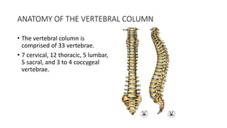
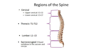
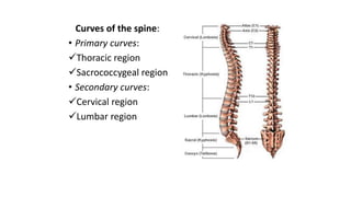
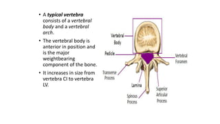
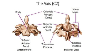
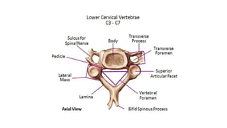
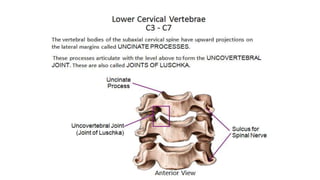
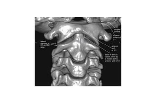
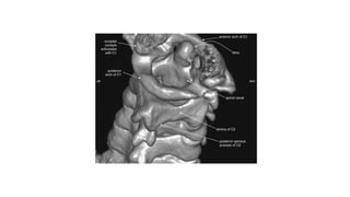
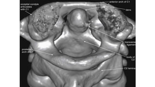
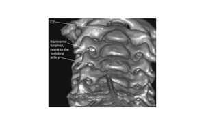
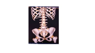
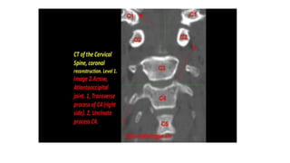
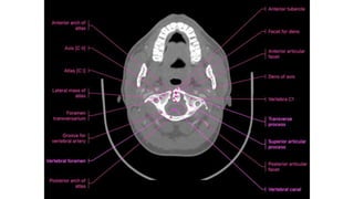
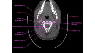
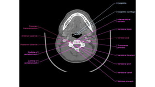
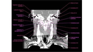
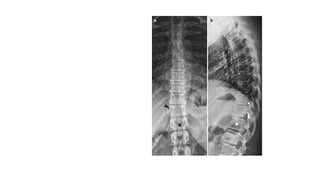
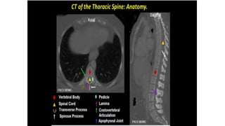
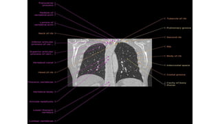
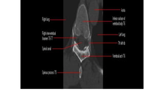
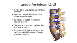
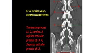
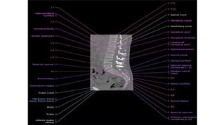
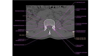
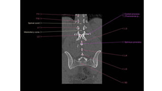
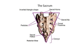
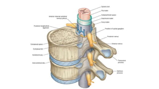
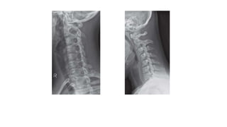
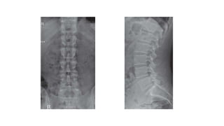
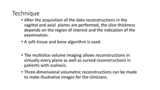
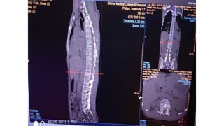
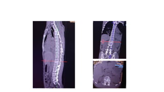
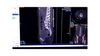
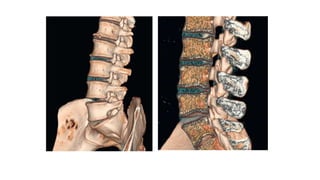
This document provides an overview of CT imaging of the cervical spine. It discusses the anatomy of the cervical spine including the typical vertebrae and curves. It describes the techniques used in CT imaging, including positioning the patient and acquiring scans to allow reconstruction in multiple planes. CT is useful for trauma evaluation and detecting fractures. Example images show normal anatomy on CT as well as a burst fracture. The document also provides some basics on lumbar spine and pelvis anatomy.
2. ANATOMY OF THE VERTEBRAL COLUMN
ā¢ The vertebral column is
comprised of 33 vertebrae.
ā¢ 7 cervical, 12 thoracic, 5 lumbar,
5 sacral, and 3 to 4 coccygeal
vertebrae.
3.
4. Curves of the spine:
ā¢ Primary curves:
ļ¼Thoracic region
ļ¼Sacrococcygeal region
ā¢ Secondary curves:
ļ¼Cervical region
ļ¼Lumbar region
5. ā¢ A typical vertebra
consists of a vertebral
body and a vertebral
arch.
ā¢ The vertebral body is
anterior in position and
is the major
weightbearing
component of the bone.
ā¢ It increases in size from
vertebra CI to vertebra
LV.
6.
7.
8.
9.
10.
11.
12. This three-dimensional reconstruction from computed tomography (CT) axial images focuses on the occipitalā
cervical junction and the C1-2 (atlantoaxial) junction
13. The skull base has been cut away nearly completely in this
CT model, allowing the ring of C1 and its relationship to the
dens of C2 to be seen in detail.
C1 and C2 view of the normal cervical spine
14.
15. This three-dimensional CT model is oriented with the observer looking cephalad along the anterior
surface of the cervical spine. A series of holes perforating the transverse processes of each vertebra
can be seenāthe transverse foramen.
16.
17.
18.
19. ā¢ Normal cervical spine.
ā¢ Five lines
ā¢ A : the anterior longitudinal
line
ā¢ P: Posterior longitudinal line.
ā¢ These run along the margin of
the anterior and posterior
longitudinal ligament.
ā¢ L is the spinolaminar line,
which runs between the
anterior margin of the dorsal
spines, outlining the posterior
margin of the spinal canal.
ā¢ The asterisks represent the
spinous line, along the
posterior margin of the dorsal
spines.
ā¢ F is the posterior pillar line,
along the posterior margins of
the articular pillars
20.
21.
22.
23.
24.
25.
26.
27.
28.
29. Thoracic spine
X-ray in AP and Lateral
projections.
Vertebral body (star ) of
T12 with rib hypoplasia;
T10āT11 intervertebral
foramina (circle ); T11
right pedicle(arrowhead )
30.
31.
32.
33.
34.
35.
36.
37.
38.
39. VERTEBRAL CANAL
ā¢ The spinal cord lies within a bony canal formed by adjacent vertebrae
and soft tissue elements, the vertebral canal.
ā¢ Anterior wall: the vertebral bodies of the vertebrae, intervertebral
discs, and associated ligaments,
ā¢ Lateral walls and roof: the vertebral arches and ligaments.
42. At the cervical levels C4āC7 the average antero-
posterior diameter is 17 mm and values below 14 mm
are considered critical.
At the lumbar level a classification of spinal stenosis was
suggested by Benoist:
ā¢ Severe stenosis (< 10 mm)
ā¢ Moderate stenosis (10ā12 mm)
ā¢ Mild stenosis (12ā14 mm)
43. PLAIN RADIOGRAPHY
ā¢ Conventional X-ray imaging is a fast, easy and inexpensive
technique which offers a good overview of a large segment
of the spine.
ā¢ Plain radiography still has the advantage over CT and MRI
for the evaluation of structural malformations
ā¢ The main disadvantage of plain radiographs is the
superimposition of soft tissue and bony structures, making
the interpretation difficult.
47. COMPUTED TOMOGRAPHY
ā¢ Computed tomography of the spine is the first choice of
examination in trauma patients with a high sensitivity in
detecting fractures.
ā¢ Although MRI has become more common for the evaluation of
the disc space and the spinal canal, CT is still adequate enough
to---
ā¢ visualize the spinal cord
ā¢ exclude compression (e.g. haematoma or disc herniation)
ā¢ evaluating the posterior elements and bony changes as facet
joint pathology
ā¢ After surgery, CT can visualize the surgical materials and
evaluate possible loosening.
48. Technique
ā¢ The patient is placed in supine position on the CT table
ā¢ Modern spiral CT allows a fast and continuous
acquisition of data to obtain a full data set which makes
reconstructions in all anatomical planes as well as 3D
reconstruction possible
ā¢ A digital radiograph, also known as āTopogramā, of the
region of interest is performed to make a selection of
the volume to be imaged.
49. Technique
ā¢ After the acquisition of the data reconstructions in the
sagittal and axial planes are performed, the slice thickness
depends on the region of interest and the indication of the
examination.
ā¢ A soft-tissue and bone algorithm is used.
ā¢ The multislice volume imaging allows reconstructions in
virtually every plane as well as curved reconstructions in
patients with scoliosis.
ā¢ Three-dimensional volumetric reconstructions can be made
to make illustrative images for the clinicians.
55. ANATOMY OF PELVIS
ā¢ The bony pelvis consists of innominate bones, each
with three parts (ilium, ischium and pubis), sacrum
and coccyx.
ā¢ It protects the pelvic viscera, provides attachment
for the muscles of the trunk and lower limb, and
enables stable transfer of the body weight from the
spine to the femur.
ā¢ Its divided into false (major) and true (minior)
pelvis, by the ileopectineal line: the smaller inferior
part is the true pelvis and the larger superior part is
the false pelvis.
56. ā¢ The false pelvis is formed mainly by the iliac fossae and
is largely filled by the iliopsoas muscles.
ā¢ The true pelvis is bounded posteriorly by the sacrum
and coccyx, laterally by the obturator membranes,
sacrospinous ligaments, and anteriorly by the pubic
bones.