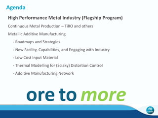
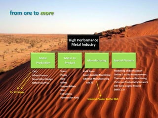
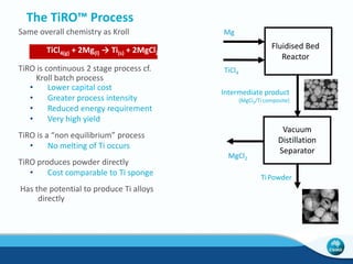
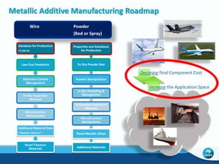
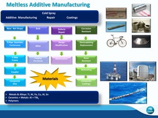
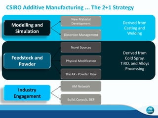
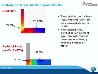
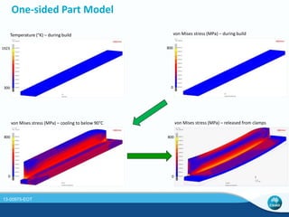
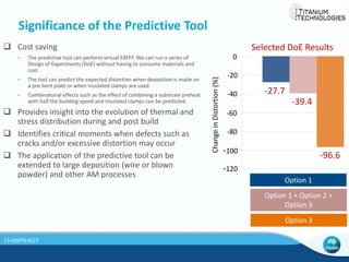
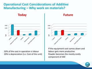
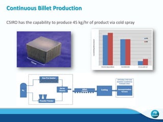
High Performance Metal Industry - 
Metallic Additive Manufacturing 
Comprehensive Overview 
Chad Henry | Additive Manufacturing Operations Manager 
Aug 2014 
MANUFACTURING FLAGSHIP
Agenda 
High Performance Metal Industry (Flagship Program) 
Continuous Metal Production – TiRO and others 
Metallic Additive Manufacturing 
- Roadmaps and Strategies 
- New Facility, Capabilities, and Engaging with Industry 
- Low Cost Input Material 
- Thermal Modelling for (Sciaky) Distortion Control 
- Additive Manufacturing Network 
ore to more
from ore to more 
High Performance 
Metal Industry 
Metal 
Production 
Metal to 
Product 
Manufacturing Special Projects 
TiRO 
Alloys Process 
Novel Alloy Design 
BMG Prod/Proc 
Sheet 
Plates 
Bars 
Billets 
Shaped Billets 
Wire 
Extrusions 
Powder (for AM) 
Cold Spray 
Laser Assisted Machining 
Additive Manufacturing 
Lab 22 
Modelling and Simulation 
Online / In Situ Measurement 
Thermally Assisted Machining 
Victorian Productivity Network 
SIEF Aero-engine Project 
DMTC 1.9 
Ti + XYZ alloys 
Universal Powder Bed for R&D
Additive Manufacturing is... 
layer-by-layer processing to make 3D objects directly from CAD files, as opposed to 
using subtractive methods like traditional CNC machining. 
Resource efficient and Sustainable 
energy efficient 
reduces waste
Lab 22 – Arcam High Speed Video - Contour
Lab 22 – Arcam High Speed Video – Fill Rastering
Metallic Additive Manufacturing Roadmap 
Wire Powder 
Database for Production 
•Ti 6Al 4V 
Low Cost Feedstock 
Distortion Control 
Management 
In Situ Inspection 
Methods 
Microstructure 
Manipulation 
Additional Material Data 
•Titanium, Steel or ? 
Novel Titanium 
Materials 
(Bed or Spray) 
Properties and Databases 
for Production 
Ex Situ Powder Bed 
Powder Manipulation 
In Situ Modelling & 
Management 
In Chamber Inspection 
Methods 
Microstructure 
Manipulation 
Novel Metallic Alloys 
Additional Materials 
Decrease final Component Cost 
Increase the Application Space
Meltless Additive Manufacturing 
Cold Spray 
Additive Manufacturing Repair Coatings 
Near Net Shape 
Ti Pipe Seamless 
Continuous 
Ti Bike 
Frame 
Ti 
Coupler 
Composite 
Dies 
Defects 
Repair 
Corrosion 
Resistant 
Electroplating 
Replacement 
Design 
Modification 
Wear 
Resistant 
Biofowling 
Composite 
Coatings 
Bulk 
Billet 
Forging 
Pre forms 
Reclamation 
Materials 
 Metals & Alloys: Ti, Ni, Fe, Cu, Al, Sn 
 Ceramics + Metals: Al + TiB2 
 Polymers
CSIRO Additive Manufacturing ... The 2+1 Strategy 
Modelling and 
Simulation 
Feedstock and 
Powder 
New Material 
Development 
Distortion Management 
Novel Sources 
Physical Modification 
The AX - Powder Flow 
Industry 
Engagement 
AM Network 
Build, Consult, SIEF 
Derived from 
Casting and 
Welding 
Derived from 
Cold Spray, 
TiRO, and Alloys 
Processing
New and Improved Facilities for Metallic AM 
• CSIRO has an open house policy to Industry and for R&D 
• De-risk to aid in Industry Adoption and Growth 
• Access our capital equipment 
• Access our trained operators 
• Trial and Learn Metallic AM 
• AĐĐess us foƌ assistaŶĐe oŶ DeǀelopiŶg BusiŶess Cases aŶd Positiǀe ROI’s 
• Access us for assistance on design (or re-designing) to take advantage of 3DP 
(d) 
Design Freedoms 
• Access us for assistance on material science solutions 
• Learn first-hand 
• Technologies (next slides) 
• Powder Beds – E-Beam and Laser 
• Powder Spray – 3D Deposition, Cold Spray, and Laser Cladding 
• Sand Printing – For Metallic Castings 
P.S. – It needs a name. Contact me if you have a clever one that you are willing to share.
E-Beam AM Equipment 
Arcam Model A1 
- Electron Beam Melting (EBM) 
- Powder Bed 
- Vacuum 
- Elevated Temp 
- Low Distortion 
- Excellent Properties 
- Model A1 
- 200mm x 200mm x 180mm 
- Materials 
- Ti and Ti Alloys 
- CoCr 
- Nickel Alloys (Inconel) 
- Steel Alloys 
- Others??? 
- CSRIO Level 3 Training
Concept Laser M2 cusing 
• Laser fusion powder bed 
• 250 x 250 x 280 (mm) chamber build volume 
• 400W beam power 
• Very good part roughness Ra 9-12mm, Rz 35- 
40mm (Ti-64) 
• <55cm3/h build rate (Ti-64) 
• Inert gas environment 
• Standard LaserCUSING materials include: 
Stainless steel 1.4404 / CL 20ES 
Aluminium alloy AlSi12 / CL 30AL 
Aluminium alloy AlSi10Mg / CL 31AL 
Titanium alloy Ti6Al4V / CL 40TI 
Titanium alloy Ti6Al4V ELI / CL 41TI ELI 
Hot-forming steel 1.2709 / CL 50WS 
Rust-free hot-forming steel CL 91RW 
Nickel-based alloy Inconel 718 / CL 100NB 
Cobalt/chrome alloy remanium star CL 
• Moderate residual stress 
• Prototyping, design, customising, light-weighting
Optomec LENS MR-7 
• IPG Fiďƌe Laseƌ ͞ďloǁŶ poǁdeƌ͟ 
• 300 x 300 x 300 (mm) chamber build volume 
• 500W beam power 
• Two powder feeder (layered composition profiles) 
• Part roughness Ra 20-50mm (Rz 150-300mm) 
• 22cm3/h build rate (Ti-64) (much higher build rates for 
other LENS variants 
• High purity inert gas (O2 ≤ ϭϬ ppŵ) 
• High residual stress 
• Optomec materials: *Non-standard Materials used in R&D 
Titanium Nickel Tool Steel 
CP Ti, Ti 6-4, Ti 6-2-4-2 
Ti 6-2-4-6*, Ti 48-2-2*, 
Ti 22AI-23Nb* 
IN625,IN718,IN690*, Hastelloy 
X*, Waspalloy, MarM247*, 
Rene 142* 
H13, S7, A-2* 
Stainless Steel Refractories Composites 
13-8, 17-4, 304, 316, 410,420, 
15-5PH*, AM355*, 309*, 416* 
W*, Mo*, N* TiC*, WC, CrC* 
Cobalt Aluminum Copper 
Stellite 21 4047 GRCop-84*, Cu-Ni* 
• Repair, prototyping, design, customising, light-weighting, 
alloy design, composite materials
Cold Spray Technologies 
Plasma Giken PCS-1000 
CGT Kinetiks 4000
Voxeljet
9 
Metal Additive Manufacturing Landscape Today 
National Aeronautics and Space Administration 
Langley Research Center
Must Understand ... One Size Does Not Fit All 
Product Requirements  Manufacturing Processes 
Material 
Build Volume 
Rate 
Design and Unitization 
Unique Shapes/Details (free) 
Surface Finish 
Inspection 
Laser vs. 
E-Beam vs. 
Solid State 
Powder Bed vs. 
Powder Spray vs. 
Wire Fed 
All for ... 
Production 
Prototyping (form, fit, function) 
Tooling 
Rapid Design 
Shop Aids 
Ti 
Ni 
Al
Titanium Technologies and Lab 22 Achievements 
• Since Sept of 2012, Lab 22 has 3D printed over 700 pieces in titanium from over 150 files 
for 52 entities in 130 total Arcam EBM builds. That is an average of 1.5 builds per week. 
Of these, 54% have been for industry, 21% have been for R&D, and 25% have been for 
marketing, media, and education. In 2012 we hosted 134 visitors, in 2013 it was 216, and 
at the end of the first quarter of 2014 it was over 100 (total >450). 
• MPs - Adam Bandt, Julie Bishop, Anna Burke, Greg Combet 
• EVP of the Lockheed Martin F-35 Joint Strike Fighter Program, Tom Burbage 
• Lab 22 Chosen to be a Preferred Service Provider for Arcam EBM 
• AM Fish Anchors Implemented (upcoming slide) 
• AM Bicycle with Flying Machine (upcoming slide) 
• AM Mining Drill Bit Holders 
• AM Bugs (upcoming slide) 
• AM Orthotic Horse Shoes 
• AM Design Optimisation via student projects (upcoming slide) 
• AM of Aero Engine Demonstration with SIEF (upcoming slide) 
• AM Network (upcoming slide)
Rapid Design Iteration 
Manufacture all of the design candidates at once in a single build. 
Inexpensive physical testing was 
employed to make decisions.
Making the Business Case with Flying Machine 
Three Conditions Together Made the Product Marketable 
 Design Change for Every Customer Possible 
 Off-The-Shelf Tubing 
 The Novelty 
http://www.flyingmachine.com.au/2014/01/3d-printed-titanium-bike-of-the-future/ 
http://www.youtube.com/watch?v=_gOd3w69kh4
Topology and Design Optimisation 
Same Performance ... Less Weight 
Iteration 1 Iteration 6 Iteration 9 Iteration 13 
Iteration 16 Iteration 20 Iteration 25 Iteration 29
SIEF Aero-engine AM Project with Monash University
I like big bugs ...
Sciaky DM Process (and CSIRO Modeling and Simulation) 
13-00975-EOT
Sciaky DM Process and CSIRO Modeling and Simulation 
 Electron Beam Freeform Fabrication (EBFFF) is an additive 
manufacturing (AM) process that works efficiently with a variety 
of weldable alloys. 
 Residual stress and shape distortion are inherent features of AM, 
particularly at high deposition rates, as a result of the large 
thermal gradients. 
 Fabricated parts are stress-relief heat treated both during and 
after deposition to help relieve stresses, which adds to cycle time 
and the overall cost. 
 CSIRO has established and implemented modelling techniques 
to predict distortion and stresses during and after deposition by 
EBFFF as a first step towards developing an active distortion 
management system. 
 The model can be employed in a predictive mode to investigate 
the effects of various tool paths and process parameters on the 
(post-manufacturing) part distortion and residual stress. 
13-00975-EOT
FEA Model of a T-shaped part 
- Substrate plate: 600 mm long, 12.5 mm thick, 100 mm wide 
- Deposit: 51 mm tall, 11.8 mm wide, single bead 
- Process parameters: 
• Speed: 12.7 mm/s 
• EB power: 4.3 kW for preheat and 8.6 kW for deposit 
• 18 layers per side; each layer is 2.83 mm high 
• Substrate and wire have initial temperature of 30°C 
Model of the part 
12.5 
T-shaped part built by EBFFF 
13-00975-EOT
Neutron Diffraction Used to Improve Results 
Prediction 
200 MPa 
- 135.2 MPa 
- 94 MPa 
Residual Stress 
by ND (ANSTO) 
235 MPa 
 The predictive tool has been 
recently refined further by 
using an updated material 
model. 
 The predicted stress 
distribution is in excellent 
agreement with residual 
stress measurements by 
neutron diffraction at 
ANSTO. 
13-00975-EOT
One-sided Part Model 
1923 
300 
Temperature (°K) – during build von Mises stress (MPa) – during build 
800 
0 
von Mises stress (MPa) – cooling to below 90°C von Mises stress (MPa) – released from clamps 
800 
0 
800 
0 
13-00975-EOT
Significance of the Predictive Tool 
 Cost saving 
‒ The predictive tool can perform virtual EBFFF. We can run a series of 
Design of Experiments (DoE) without having to consume materials and 
cost 
‒ The tool can predict the expected distortion when deposition is made on 
a pre-bent plate or when insulated clamps are used 
‒ Combinatorial effects such as the effect of combining a substrate preheat 
with half the building speed and insulated clamps can be predicted. 
 Provides insight into the evolution of thermal and 
stress distribution during and post build 
 Identifies critical moments when defects such as 
cracks and/or excessive distortion may occur 
 The application of the predictive tool can be 
extended to large deposition (wire or blown 
powder) and other AM processes 
Selected DoE Results 
-96.6 
-39.4 
-27.7 
0 
-20 
-40 
-60 
-80 
-100 
-120 
Change in Distortion (%) 
Option 1 
Option 1 + Option 2 + 
Option 3 
Option 3 
13-00975-EOT
Operational Cost Considerations of Additive 
Manufacturing – Why work on materials? 
2000 
1500 
1000 
500 
$ $ 
0 
Today Future 
2000 
1500 
1000 
500 
0 
50% of the cost in operation is labour 
20% is depreciation (i.e. Cost of the unit) 
If the equipment cost comes down and 
labour gets more productive 
Powder becomes the mostly costly 
component of AM
Where is ͞Cheap͟ TitaŶiuŵ Powder??? 
Armstrong Process – Cristal 
FFC Process – Metalysis 
TiRO 
Alloys 
CSIR 
New Zealand 
Hydride DeHydride 
ADMA 
China
Powder, Particles and Aggregate 
Size 
Size Range 
Flow 
Density 
Alter Either or Both: 
- Improve the Inexpensive Powder 
- Alter the AM Equipment Operating Parameters
CSIRO Powder Manipulation 
50 
25 
>1000 600 – 
1000 
400 – 
600 
250 – 
400 
150 – 
250 
100 – 
150 
75 – 
100 
45 – 
75 
25 – 
45 
< 25 
E-Beam 
AM 
Laser AM, 
Cold Spray 
Weight 
pct 
Particle Size in mm 
Before 
After
Universal Powder Bed 
External laboratory bench-top unit to allow for studies of how low cost input material actually 
behaves without being encumbered by a full AM system. 
Powder hopper 
25 kg of Ti each 
Powder table 
Rake regulator 
Optical 
Camera 
Heat shield 
Rake 
Build tank
Cold Spray Technology 
CSIRO has developed a new 
solid-state additive 
manufacturing process using 
Cold Spray Technology to 
produce bulk 3D forms and 
coatings from powder feed 
stock that is both metallic 
and non-metallic.
Process and applications 
• During cold spray, powder particles (typically 10 to 50 μm) are 
accelerated to high velocities (200 to 1200 m.s-1) by a 
supersonic compressed gas jet at temperatures well below 
their melting point. As the particles impact the surface they 
undergo large plastic deformations, consolidating to produce 
localised forge bonding, at spray rates up to several 100 g/min. 
• The deposition efficiency is also very high, above 95% in most 
cases. 
• The technology is more efficient, cost effective and 
environmentally friendly and can be applied to the aerospace, 
biomedical, oil and gas, power generation, motor sport, 
petrochemical and electronics industries. 
• Our 3D simulation outcomes has proved to be highly cost 
effective for optimization of the cold spray parameters.
Research at CSIRO 
Preforms, Billet and Pipe 
Coatings on polymer and metal 
3D manufacturing of bulk 
billet and preforms 
Repair and modification 
techniques for lightweight 
aerospace alloys 
Improved biocompatible 
coatings for medical implants 
Thick metallic coatings for 
thermally sensitive substrates 
Ballistic protection composite 
coating for defence and space 
application 
Anti-fouling coatings for 
marine application
Advantages of Cold Spray 
 Solid-state deposition - no melting 
therefore no solidification defects 
 No vacuum required for oxygen 
sensitive materials such as Ti 
 Environmentally friendly process 
 Cost effective - capital and 
operation 
Cold Sprayed CP Ti 
Conventional CP Ti
Cold Spray for Pre-forms
Continuous Billet Production 
CSIRO has the capability to produce 45 kg/hr of product via cold spray
The Additive Manufacturing Network 
The hub for all things additive. 
MISSION – Coordinate additive manufacturing for Australia. 
The Additive Manufacturing Network is ... 
- Public with participation from academia, industry, and 
government welcome. 
- To be self governed once established. 
- Well poised to be a self supporting national asset. 
GOAL – Market globally Australian additive manufacturing 
capability, for both technology R&D and production for profit 
in industry. 
- Publish who has what equipment and corresponding capabilities. 
- Create confidence in global customers investigating Australian potential. 
- Collaborate efficiently for new Australian business, creating greater total 
revenues in which to participate. 
- Connect those with a need to those with a solution. 
Per the mission statement: 
co·or·di·nate (verb) - The act of 
harmoniously combining and interacting 
items to function effectively. 
GOAL – Facilitate communication within 
Australia on additive manufacturing. 
- Use a network infrastructure, including focused 
working groups, to conduct regular face-to-face and 
web meetings. 
- UŶdeƌstaŶd otheƌs’ ƌoadŵaps aŶd stƌategies. 
- Coordinate and be efficient on resolving issues. 
- Achieve a comprehensive and non-redundant R&D 
project portfolio within the country. 
- Accelerate the deployment of technologies to 
industry. 
Status 
- A survey of industry was taken and interest existed. 
- Kickoff Meeting 
- Inaugural Committee of 10. 
- Now Partnered with (i.e. handed over) to AMTIL. 
For further information, please contact: 
Chad Henry 
CSIRO 
Additive Manufacturing Operations Manager 
Titanium Technologies Stream Leader 
Gate 7 Normanby Road, Clayton 3168 VIC Australia 
+61 3 9545 7844 (office) 
chad.henry@csiro.au
Thank you 
CSIRO Manufacturing Flagship 
High Performance Metal Industry 
ore to more 
Chad Henry 
Additive Manufacturing Operations Manager 
+61 (03) 9545 7844 
chad.henry@csiro.au 
FUTURE MANUFACTURING FLAGSHIP

CSIRO Additive Manufacturing - Aug 14

  • 1.
    High Performance MetalIndustry - Metallic Additive Manufacturing Comprehensive Overview Chad Henry | Additive Manufacturing Operations Manager Aug 2014 MANUFACTURING FLAGSHIP
  • 2.
    Agenda High PerformanceMetal Industry (Flagship Program) Continuous Metal Production – TiRO and others Metallic Additive Manufacturing - Roadmaps and Strategies - New Facility, Capabilities, and Engaging with Industry - Low Cost Input Material - Thermal Modelling for (Sciaky) Distortion Control - Additive Manufacturing Network ore to more
  • 3.
    from ore tomore High Performance Metal Industry Metal Production Metal to Product Manufacturing Special Projects TiRO Alloys Process Novel Alloy Design BMG Prod/Proc Sheet Plates Bars Billets Shaped Billets Wire Extrusions Powder (for AM) Cold Spray Laser Assisted Machining Additive Manufacturing Lab 22 Modelling and Simulation Online / In Situ Measurement Thermally Assisted Machining Victorian Productivity Network SIEF Aero-engine Project DMTC 1.9 Ti + XYZ alloys Universal Powder Bed for R&D
  • 4.
    Additive Manufacturing is... layer-by-layer processing to make 3D objects directly from CAD files, as opposed to using subtractive methods like traditional CNC machining. Resource efficient and Sustainable energy efficient reduces waste
  • 5.
    Lab 22 –Arcam High Speed Video - Contour
  • 6.
    Lab 22 –Arcam High Speed Video – Fill Rastering
  • 7.
    Metallic Additive ManufacturingRoadmap Wire Powder Database for Production •Ti 6Al 4V Low Cost Feedstock Distortion Control Management In Situ Inspection Methods Microstructure Manipulation Additional Material Data •Titanium, Steel or ? Novel Titanium Materials (Bed or Spray) Properties and Databases for Production Ex Situ Powder Bed Powder Manipulation In Situ Modelling & Management In Chamber Inspection Methods Microstructure Manipulation Novel Metallic Alloys Additional Materials Decrease final Component Cost Increase the Application Space
  • 8.
    Meltless Additive Manufacturing Cold Spray Additive Manufacturing Repair Coatings Near Net Shape Ti Pipe Seamless Continuous Ti Bike Frame Ti Coupler Composite Dies Defects Repair Corrosion Resistant Electroplating Replacement Design Modification Wear Resistant Biofowling Composite Coatings Bulk Billet Forging Pre forms Reclamation Materials  Metals & Alloys: Ti, Ni, Fe, Cu, Al, Sn  Ceramics + Metals: Al + TiB2  Polymers
  • 9.
    CSIRO Additive Manufacturing... The 2+1 Strategy Modelling and Simulation Feedstock and Powder New Material Development Distortion Management Novel Sources Physical Modification The AX - Powder Flow Industry Engagement AM Network Build, Consult, SIEF Derived from Casting and Welding Derived from Cold Spray, TiRO, and Alloys Processing
  • 10.
    New and ImprovedFacilities for Metallic AM • CSIRO has an open house policy to Industry and for R&D • De-risk to aid in Industry Adoption and Growth • Access our capital equipment • Access our trained operators • Trial and Learn Metallic AM • AĐĐess us foƌ assistaŶĐe oŶ DeǀelopiŶg BusiŶess Cases aŶd Positiǀe ROI’s • Access us for assistance on design (or re-designing) to take advantage of 3DP (d) Design Freedoms • Access us for assistance on material science solutions • Learn first-hand • Technologies (next slides) • Powder Beds – E-Beam and Laser • Powder Spray – 3D Deposition, Cold Spray, and Laser Cladding • Sand Printing – For Metallic Castings P.S. – It needs a name. Contact me if you have a clever one that you are willing to share.
  • 11.
    E-Beam AM Equipment Arcam Model A1 - Electron Beam Melting (EBM) - Powder Bed - Vacuum - Elevated Temp - Low Distortion - Excellent Properties - Model A1 - 200mm x 200mm x 180mm - Materials - Ti and Ti Alloys - CoCr - Nickel Alloys (Inconel) - Steel Alloys - Others??? - CSRIO Level 3 Training
  • 12.
    Concept Laser M2cusing • Laser fusion powder bed • 250 x 250 x 280 (mm) chamber build volume • 400W beam power • Very good part roughness Ra 9-12mm, Rz 35- 40mm (Ti-64) • <55cm3/h build rate (Ti-64) • Inert gas environment • Standard LaserCUSING materials include: Stainless steel 1.4404 / CL 20ES Aluminium alloy AlSi12 / CL 30AL Aluminium alloy AlSi10Mg / CL 31AL Titanium alloy Ti6Al4V / CL 40TI Titanium alloy Ti6Al4V ELI / CL 41TI ELI Hot-forming steel 1.2709 / CL 50WS Rust-free hot-forming steel CL 91RW Nickel-based alloy Inconel 718 / CL 100NB Cobalt/chrome alloy remanium star CL • Moderate residual stress • Prototyping, design, customising, light-weighting
  • 13.
    Optomec LENS MR-7 • IPG Fiďƌe Laseƌ ͞ďloǁŶ poǁdeƌ͟ • 300 x 300 x 300 (mm) chamber build volume • 500W beam power • Two powder feeder (layered composition profiles) • Part roughness Ra 20-50mm (Rz 150-300mm) • 22cm3/h build rate (Ti-64) (much higher build rates for other LENS variants • High purity inert gas (O2 ≤ ϭϬ ppŵ) • High residual stress • Optomec materials: *Non-standard Materials used in R&D Titanium Nickel Tool Steel CP Ti, Ti 6-4, Ti 6-2-4-2 Ti 6-2-4-6*, Ti 48-2-2*, Ti 22AI-23Nb* IN625,IN718,IN690*, Hastelloy X*, Waspalloy, MarM247*, Rene 142* H13, S7, A-2* Stainless Steel Refractories Composites 13-8, 17-4, 304, 316, 410,420, 15-5PH*, AM355*, 309*, 416* W*, Mo*, N* TiC*, WC, CrC* Cobalt Aluminum Copper Stellite 21 4047 GRCop-84*, Cu-Ni* • Repair, prototyping, design, customising, light-weighting, alloy design, composite materials
  • 14.
    Cold Spray Technologies Plasma Giken PCS-1000 CGT Kinetiks 4000
  • 15.
  • 16.
    9 Metal AdditiveManufacturing Landscape Today National Aeronautics and Space Administration Langley Research Center
  • 17.
    Must Understand ...One Size Does Not Fit All Product Requirements  Manufacturing Processes Material Build Volume Rate Design and Unitization Unique Shapes/Details (free) Surface Finish Inspection Laser vs. E-Beam vs. Solid State Powder Bed vs. Powder Spray vs. Wire Fed All for ... Production Prototyping (form, fit, function) Tooling Rapid Design Shop Aids Ti Ni Al
  • 18.
    Titanium Technologies andLab 22 Achievements • Since Sept of 2012, Lab 22 has 3D printed over 700 pieces in titanium from over 150 files for 52 entities in 130 total Arcam EBM builds. That is an average of 1.5 builds per week. Of these, 54% have been for industry, 21% have been for R&D, and 25% have been for marketing, media, and education. In 2012 we hosted 134 visitors, in 2013 it was 216, and at the end of the first quarter of 2014 it was over 100 (total >450). • MPs - Adam Bandt, Julie Bishop, Anna Burke, Greg Combet • EVP of the Lockheed Martin F-35 Joint Strike Fighter Program, Tom Burbage • Lab 22 Chosen to be a Preferred Service Provider for Arcam EBM • AM Fish Anchors Implemented (upcoming slide) • AM Bicycle with Flying Machine (upcoming slide) • AM Mining Drill Bit Holders • AM Bugs (upcoming slide) • AM Orthotic Horse Shoes • AM Design Optimisation via student projects (upcoming slide) • AM of Aero Engine Demonstration with SIEF (upcoming slide) • AM Network (upcoming slide)
  • 19.
    Rapid Design Iteration Manufacture all of the design candidates at once in a single build. Inexpensive physical testing was employed to make decisions.
  • 20.
    Making the BusinessCase with Flying Machine Three Conditions Together Made the Product Marketable  Design Change for Every Customer Possible  Off-The-Shelf Tubing  The Novelty http://www.flyingmachine.com.au/2014/01/3d-printed-titanium-bike-of-the-future/ http://www.youtube.com/watch?v=_gOd3w69kh4
  • 21.
    Topology and DesignOptimisation Same Performance ... Less Weight Iteration 1 Iteration 6 Iteration 9 Iteration 13 Iteration 16 Iteration 20 Iteration 25 Iteration 29
  • 22.
    SIEF Aero-engine AMProject with Monash University
  • 23.
    I like bigbugs ...
  • 24.
    Sciaky DM Process(and CSIRO Modeling and Simulation) 13-00975-EOT
  • 25.
    Sciaky DM Processand CSIRO Modeling and Simulation  Electron Beam Freeform Fabrication (EBFFF) is an additive manufacturing (AM) process that works efficiently with a variety of weldable alloys.  Residual stress and shape distortion are inherent features of AM, particularly at high deposition rates, as a result of the large thermal gradients.  Fabricated parts are stress-relief heat treated both during and after deposition to help relieve stresses, which adds to cycle time and the overall cost.  CSIRO has established and implemented modelling techniques to predict distortion and stresses during and after deposition by EBFFF as a first step towards developing an active distortion management system.  The model can be employed in a predictive mode to investigate the effects of various tool paths and process parameters on the (post-manufacturing) part distortion and residual stress. 13-00975-EOT
  • 26.
    FEA Model ofa T-shaped part - Substrate plate: 600 mm long, 12.5 mm thick, 100 mm wide - Deposit: 51 mm tall, 11.8 mm wide, single bead - Process parameters: • Speed: 12.7 mm/s • EB power: 4.3 kW for preheat and 8.6 kW for deposit • 18 layers per side; each layer is 2.83 mm high • Substrate and wire have initial temperature of 30°C Model of the part 12.5 T-shaped part built by EBFFF 13-00975-EOT
  • 27.
    Neutron Diffraction Usedto Improve Results Prediction 200 MPa - 135.2 MPa - 94 MPa Residual Stress by ND (ANSTO) 235 MPa  The predictive tool has been recently refined further by using an updated material model.  The predicted stress distribution is in excellent agreement with residual stress measurements by neutron diffraction at ANSTO. 13-00975-EOT
  • 28.
    One-sided Part Model 1923 300 Temperature (°K) – during build von Mises stress (MPa) – during build 800 0 von Mises stress (MPa) – cooling to below 90°C von Mises stress (MPa) – released from clamps 800 0 800 0 13-00975-EOT
  • 29.
    Significance of thePredictive Tool  Cost saving ‒ The predictive tool can perform virtual EBFFF. We can run a series of Design of Experiments (DoE) without having to consume materials and cost ‒ The tool can predict the expected distortion when deposition is made on a pre-bent plate or when insulated clamps are used ‒ Combinatorial effects such as the effect of combining a substrate preheat with half the building speed and insulated clamps can be predicted.  Provides insight into the evolution of thermal and stress distribution during and post build  Identifies critical moments when defects such as cracks and/or excessive distortion may occur  The application of the predictive tool can be extended to large deposition (wire or blown powder) and other AM processes Selected DoE Results -96.6 -39.4 -27.7 0 -20 -40 -60 -80 -100 -120 Change in Distortion (%) Option 1 Option 1 + Option 2 + Option 3 Option 3 13-00975-EOT
  • 30.
    Operational Cost Considerationsof Additive Manufacturing – Why work on materials? 2000 1500 1000 500 $ $ 0 Today Future 2000 1500 1000 500 0 50% of the cost in operation is labour 20% is depreciation (i.e. Cost of the unit) If the equipment cost comes down and labour gets more productive Powder becomes the mostly costly component of AM
  • 31.
    Where is ͞Cheap͟TitaŶiuŵ Powder??? Armstrong Process – Cristal FFC Process – Metalysis TiRO Alloys CSIR New Zealand Hydride DeHydride ADMA China
  • 32.
    Powder, Particles andAggregate Size Size Range Flow Density Alter Either or Both: - Improve the Inexpensive Powder - Alter the AM Equipment Operating Parameters
  • 33.
    CSIRO Powder Manipulation 50 25 >1000 600 – 1000 400 – 600 250 – 400 150 – 250 100 – 150 75 – 100 45 – 75 25 – 45 < 25 E-Beam AM Laser AM, Cold Spray Weight pct Particle Size in mm Before After
  • 34.
    Universal Powder Bed External laboratory bench-top unit to allow for studies of how low cost input material actually behaves without being encumbered by a full AM system. Powder hopper 25 kg of Ti each Powder table Rake regulator Optical Camera Heat shield Rake Build tank
  • 35.
    Cold Spray Technology CSIRO has developed a new solid-state additive manufacturing process using Cold Spray Technology to produce bulk 3D forms and coatings from powder feed stock that is both metallic and non-metallic.
  • 36.
    Process and applications • During cold spray, powder particles (typically 10 to 50 μm) are accelerated to high velocities (200 to 1200 m.s-1) by a supersonic compressed gas jet at temperatures well below their melting point. As the particles impact the surface they undergo large plastic deformations, consolidating to produce localised forge bonding, at spray rates up to several 100 g/min. • The deposition efficiency is also very high, above 95% in most cases. • The technology is more efficient, cost effective and environmentally friendly and can be applied to the aerospace, biomedical, oil and gas, power generation, motor sport, petrochemical and electronics industries. • Our 3D simulation outcomes has proved to be highly cost effective for optimization of the cold spray parameters.
  • 37.
    Research at CSIRO Preforms, Billet and Pipe Coatings on polymer and metal 3D manufacturing of bulk billet and preforms Repair and modification techniques for lightweight aerospace alloys Improved biocompatible coatings for medical implants Thick metallic coatings for thermally sensitive substrates Ballistic protection composite coating for defence and space application Anti-fouling coatings for marine application
  • 38.
    Advantages of ColdSpray  Solid-state deposition - no melting therefore no solidification defects  No vacuum required for oxygen sensitive materials such as Ti  Environmentally friendly process  Cost effective - capital and operation Cold Sprayed CP Ti Conventional CP Ti
  • 39.
    Cold Spray forPre-forms
  • 40.
    Continuous Billet Production CSIRO has the capability to produce 45 kg/hr of product via cold spray
  • 41.
    The Additive ManufacturingNetwork The hub for all things additive. MISSION – Coordinate additive manufacturing for Australia. The Additive Manufacturing Network is ... - Public with participation from academia, industry, and government welcome. - To be self governed once established. - Well poised to be a self supporting national asset. GOAL – Market globally Australian additive manufacturing capability, for both technology R&D and production for profit in industry. - Publish who has what equipment and corresponding capabilities. - Create confidence in global customers investigating Australian potential. - Collaborate efficiently for new Australian business, creating greater total revenues in which to participate. - Connect those with a need to those with a solution. Per the mission statement: co·or·di·nate (verb) - The act of harmoniously combining and interacting items to function effectively. GOAL – Facilitate communication within Australia on additive manufacturing. - Use a network infrastructure, including focused working groups, to conduct regular face-to-face and web meetings. - UŶdeƌstaŶd otheƌs’ ƌoadŵaps aŶd stƌategies. - Coordinate and be efficient on resolving issues. - Achieve a comprehensive and non-redundant R&D project portfolio within the country. - Accelerate the deployment of technologies to industry. Status - A survey of industry was taken and interest existed. - Kickoff Meeting - Inaugural Committee of 10. - Now Partnered with (i.e. handed over) to AMTIL. For further information, please contact: Chad Henry CSIRO Additive Manufacturing Operations Manager Titanium Technologies Stream Leader Gate 7 Normanby Road, Clayton 3168 VIC Australia +61 3 9545 7844 (office) chad.henry@csiro.au
  • 42.
    Thank you CSIROManufacturing Flagship High Performance Metal Industry ore to more Chad Henry Additive Manufacturing Operations Manager +61 (03) 9545 7844 chad.henry@csiro.au FUTURE MANUFACTURING FLAGSHIP