Downloaded 161 times
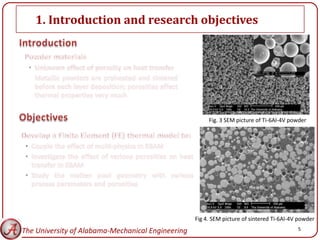
![1. Introduction and research objectives
Fig. 1 Melt ball formation [2]
Fig. 2 Delamination [2] 4
The University of Alabama-Mechanical Engineering](https://image.slidesharecdn.com/msec2012-130214121537-phpapp01/85/Thermal-Modeling-of-Electron-Beam-Additive-Manufacturing-Process-Powder-Sintering-Effects-4-320.jpg)
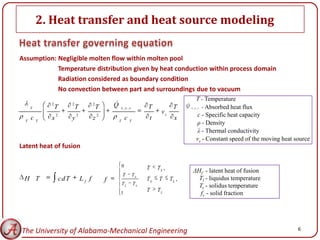
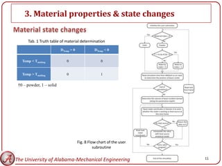
![2. Heat transfer and heat source modeling
• The cross sectional geometry of keyhole is usually idealized as a cone
• The intensity distribution is considered as a conical source:
Horizontal – Gaussian distribution
Vertical – Decaying with increasing of penetration depth
Fig. 5 Actual keyhole example and idealization [3]
The University of Alabama-Mechanical Engineering 7](https://image.slidesharecdn.com/msec2012-130214121537-phpapp01/85/Thermal-Modeling-of-Electron-Beam-Additive-Manufacturing-Process-Powder-Sintering-Effects-7-320.jpg)
![2. Heat transfer and heat source modeling
Heat source equation used in our study [4]:
2 2
8 UIb 8 x xs y ys
2 z
S x, y, z f z 2
exp 2 with f z 1
E E
h h
Max. density = 306 W/mm2
U 6 0 kV
Ib 2mA
If E
2mm
1
h 2mm
z 0
Fig. 6 Horizontal intensity distribution @ z = 0
The University of Alabama-Mechanical Engineering 8](https://image.slidesharecdn.com/msec2012-130214121537-phpapp01/85/Thermal-Modeling-of-Electron-Beam-Additive-Manufacturing-Process-Powder-Sintering-Effects-8-320.jpg)
![3. Material properties & state changes
Fig. 7 Temperature dependent material properties of Ti-6Al-4V [5]
The University of Alabama-Mechanical Engineering 9](https://image.slidesharecdn.com/msec2012-130214121537-phpapp01/85/Thermal-Modeling-of-Electron-Beam-Additive-Manufacturing-Process-Powder-Sintering-Effects-9-320.jpg)
![3. Material properties & state changes
Emissivity [6]: Thermal Conductivity [7]:
AH H
1 AH S
2 k kr kc
1
S
2 3 .0 8 2
2
0.908 16
AH 2 H 2 kc l T
3 kr k b u lk x
1.908 2 1 1
1 3 .0 8 2 1 3
S
εS – Emissivity of solid material
εH – Emissivity of the hole among adjacent powder particles
f – Fraction of total cavity surface
AH – The area fraction of the surface that is occupied by the radiation emitting holes
d – Mean pore diameter
D – Particle size
φ – Fractional porosity of the bed
l – Mean photon free path between scattering events, the particle diameter in this study
σ – Stefan-Boltzmann constant,
T – Temperature
x = b/R – Ratio of neck radius to particle radius
Λ – Normalized contact conductivity for the three packing structures.
The University of Alabama-Mechanical Engineering 10](https://image.slidesharecdn.com/msec2012-130214121537-phpapp01/85/Thermal-Modeling-of-Electron-Beam-Additive-Manufacturing-Process-Powder-Sintering-Effects-10-320.jpg)
![4. FE model configuration
Tab. 2 Parameters in the simulation
Parameters Values
Solidus temperature, TS ( C) 1605 [8]
Liquidus temperature, TL ( C) 1665 [8]
Latent heat of fusion, Lf (kJ/Kg) 440 [8]
Electron beam diameter, Φ (mm) 0.2, 0.4, 0.7, 1.0
Absorption efficiency, η 0.9 [2]
Scan speed, v (mm/sec) 400 [2]
Acceleration voltage, U (kV) 60 [2]
Beam current, Ib (mA) 0.002 [2]
Powder layer thickness, t-layer (mm) 0.1 [2]
Porosity, φ 0, 0.3, 0.45,0.6
Beam penetration depth, dP (mm) 0.1[2]
Fig. 9 New FE model configuration
Preheat temperature, Tpreheat ( C) 760 [2]
The University of Alabama-Mechanical Engineering 12](https://image.slidesharecdn.com/msec2012-130214121537-phpapp01/85/Thermal-Modeling-of-Electron-Beam-Additive-Manufacturing-Process-Powder-Sintering-Effects-12-320.jpg)
![5. Model validation
Fig. 10 Model geometry, ICs and BCs [9]
Fig. 11 Simulation results comparison with Wang et al [9]:
a) Temperature contour; b) Temperature distribution along beam center scan pass
The University of Alabama-Mechanical Engineering 13](https://image.slidesharecdn.com/msec2012-130214121537-phpapp01/85/Thermal-Modeling-of-Electron-Beam-Additive-Manufacturing-Process-Powder-Sintering-Effects-13-320.jpg)
![Reference
[1] Available from: http://www.arcam.com/.
[2] Zaeh, M. F., and Lutzmann, S., 2010, "Modelling and simulation of electron beam melting," Production
Engeering. Research and Development, 4, pp. 15-23.
[3] Lampa, C., Kaplan, A. F. H., Powell, J., and Magnusson, C., 1997, "An analytical thermodynamic model of laser
welding," Journal of Physics D: Applied Physics, 30(9), p. 1293.
[4] Rouquette, S., Guo, J., and Le Masson, P., 2007, "Estimation of the parameters of a Gaussian heat source by
the Levenberg-Marquardt method: Application to the electron beam welding," International Journal of
Thermal Sciences, 46(2), pp. 128-138.
[5] Yang, J., Sun, S., Brandt, M., and Yan, W., 2010, "Experimental investigation and 3D finite element prediction
of the heat affected zone during laser assisted machining of Ti6Al4V alloy," Journal of Materials Processing
Technology, 210(15), pp. 2215-2222.
[6] Sih, S. S., and Barlow, J. W., 2004, "The prediction of the emissivity and thermal conductivity of powder beds,"
Particulate Science and Technology, 22, pp. 291-304.
[7] Kolossov, S., Boillat, E., Glardon, R., Fischer, P., and Locher, M., 2004, "3D FE simulation for temperature
evolution in the selective laser sintering process," International Journal of Machine Tools and Manufacture,
44(2-3), pp. 117-123.
[8] Boyer, R., Welsch, G., and Collings, E. W., 1998, "Materials Properties Handbook: Titanium Alloys," ASM
InternationalMaterials Park, OH, USA, pp. 483-636.
[9] Wang, L., Felicelli, S., Gooroochurn, Y., Wang, P. T., and Horstemeyer, M. F., 2008, "Optimization of the LENS
process for steady molten pool size," Materials Science & Engineering A (Structural Materials: Properties,
Microstructure and Processing), 474, pp. 148-156.
[10] Hofmeister, W., Wert, M., Smugeresky, J., Philliber, J. A., Griffith, M., and Ensz, M. T., 1999, "Invesitigation of
solidification in the Laser Engineered Net Shaping (LENS) process," JOM, 51(7).
The University of Alabama-Mechanical Engineering 24](https://image.slidesharecdn.com/msec2012-130214121537-phpapp01/85/Thermal-Modeling-of-Electron-Beam-Additive-Manufacturing-Process-Powder-Sintering-Effects-24-320.jpg)

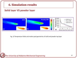
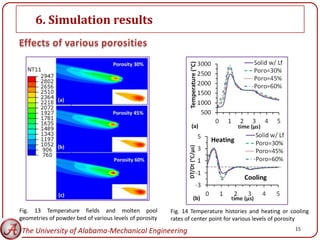
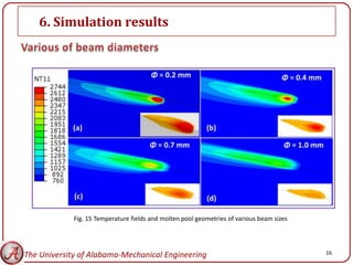
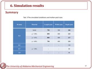
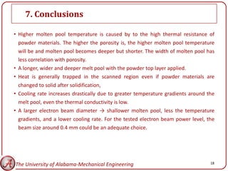
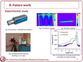
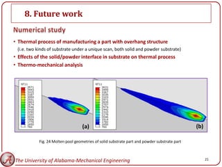
This document summarizes research on modeling the thermal effects of the electron beam additive manufacturing process, specifically how powder sintering affects temperature distribution and melt pool geometry. Key findings from simulations include higher temperatures and deeper melt pools with increasing powder porosity. Larger beam sizes produced shallower melt pools. Future work is proposed on modeling overhang structures, thermal effects at solid/powder interfaces, and thermo-mechanical analysis.


