Downloaded 134 times


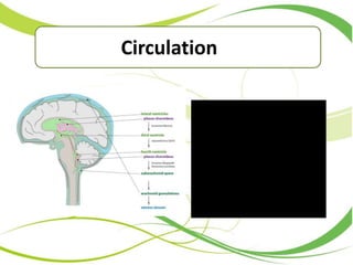

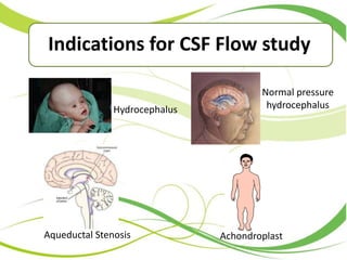


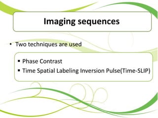


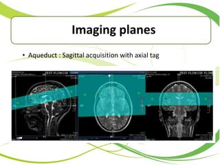


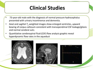


This document discusses cerebrospinal fluid (CSF) flow studies using magnetic resonance imaging (MRI). It describes CSF production, circulation, and functions. It explains phase contrast and Time-SLIP imaging sequences used to visualize CSF flow. Parameters measured from flow quantification curves are outlined. Examples of CSF flow studies in normal pressure hydrocephalus, Chiari malformation, and pre- and post-shunt placement are provided. The conclusion states that Time-SLIP is a new technique that can visualize CSF dynamics for up to 5 seconds.


