The document provides instructions for configuring Ethernet interfaces and link aggregation on Huawei switches. It includes:
1) Manually setting the line rate and duplex mode of Ethernet interfaces on switches S1 and S2 to 100Mbps full duplex.
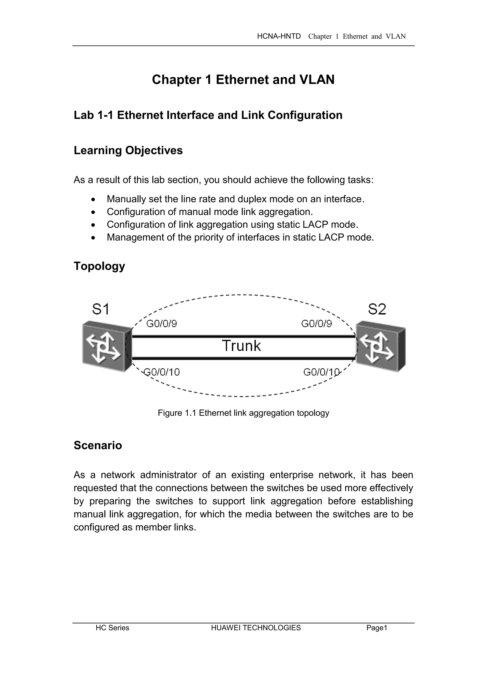
2) Creating an Ethernet trunk (Eth-Trunk 1) on S1 and S2 and adding interfaces G0/0/9 and G0/0/10 to configure manual link aggregation between the switches.
3) Deleting the manual link aggregation configurations in preparation for configuring static LACP mode aggregation on the same interfaces.


![HCNA-HNTD Chapter 1 Ethernet and VLAN
Page2 HUAWEI TECHNOLOGIES HC Series
Tasks
Step 1 Perform basic configuration on the Ethernet switches.
Auto-negotiation is enabled on Huawei switch interfaces by default. The rate
and duplex mode of G0/0/9 and G0/0/10 on S1 and S2 are to be set manually.
Change the system name and view detailed information for G0/0/9 and
G0/0/10 on S1.
<Quidway>system-view
[Quidway]sysname S1
[S1]display interface GigabitEthernet 0/0/9
GigabitEthernet0/0/9 current state : UP
Line protocol current state : UP
Description:HUAWEI, Quidway Series, GigabitEthernet0/0/9 Interface
Switch Port,PVID : 1,The Maximum Frame Length is 1600
IP Sending Frames' Format is PKTFMT_ETHNT_2, Hardware address is 0018-82e1-aea6
Port Mode: COMMON COPPER
Speed : 1000, Loopback: NONE
Duplex: FULL, Negotiation: ENABLE
Mdi : AUTO
Last 300 seconds input rate 752 bits/sec, 0 packets/sec
Last 300 seconds output rate 720 bits/sec, 0 packets/sec
Input peak rate 1057259144 bits/sec,Record time: 2008-10-01 00:08:58
Output peak rate 1057267232 bits/sec,Record time: 2008-10-01 00:08:58
Input: 11655141 packets, 960068100 bytes
Unicast : 70,Multicast : 5011357
Broadcast : 6643714,Jumbo : 0
CRC : 0,Giants : 0
Jabbers : 0,Throttles : 0
Runts : 0,DropEvents : 0
Alignments : 0,Symbols : 0
Ignoreds : 0,Frames : 0
Discard : 69,Total Error : 0
Output: 11652169 packets, 959869843 bytes
Unicast : 345,Multicast : 5009016
Broadcast : 6642808,Jumbo : 0
Collisions : 0,Deferreds : 0
Late Collisions : 0,ExcessiveCollisions: 0
Buffers Purged : 0
Discard : 5,Total Error : 0](https://image.slidesharecdn.com/hcnaintermediatelab-190422104356/75/Hcna-intermediate-lab-10-2048.jpg)
![HCNA-HNTD Chapter 1 Ethernet and VLAN
HC Series HUAWEI TECHNOLOGIES Page3
Input bandwidth utilization threshold : 100.00%
Output bandwidth utilization threshold: 100.00%
Input bandwidth utilization : 0.01%
Output bandwidth utilization : 0.00%
[S1]display interface GigabitEthernet 0/0/10
GigabitEthernet0/0/10 current state : UP
Line protocol current state : UP
Description:HUAWEI, Quidway Series, GigabitEthernet0/0/10 Interface
Switch Port,PVID : 1,The Maximum Frame Length is 1600
IP Sending Frames' Format is PKTFMT_ETHNT_2, Hardware address is 0018-82e1-aea6
Port Mode: COMMON COPPER
Speed : 1000, Loopback: NONE
Duplex: FULL, Negotiation: ENABLE
Mdi : AUTO
Last 300 seconds input rate 1312 bits/sec, 0 packets/sec
Last 300 seconds output rate 72 bits/sec, 0 packets/sec
Input peak rate 1057256792 bits/sec,Record time: 2008-10-01 00:08:58
Output peak rate 1057267296 bits/sec,Record time: 2008-10-01 00:08:58
Input: 11651829 packets, 959852817 bytes
Unicast : 115,Multicast : 5009062
Broadcast : 6642648,Jumbo : 0
CRC : 3,Giants : 0
Jabbers : 0,Throttles : 0
Runts : 0,DropEvents : 0
Alignments : 0,Symbols : 4
Ignoreds : 0,Frames : 0
Discard : 218,Total Error : 7
Output: 11655280 packets, 960072712 bytes
Unicast : 245,Multicast : 5011284
Broadcast : 6643751,Jumbo : 0
Collisions : 0,Deferreds : 0
Late Collisions : 0,ExcessiveCollisions: 0
Buffers Purged : 0
Discard : 107,Total Error : 0
Input bandwidth utilization threshold : 100.00%
Output bandwidth utilization threshold: 100.00%
Input bandwidth utilization : 0.01%
Output bandwidth utilization : 0.00%
Set the rate of G0/0/9 and G0/0/10 on S1 to 100 Mbit/s and configure them to
work in full duplex mode. Before changing the interface rate and duplex mode,
disable auto-negotiation.](https://image.slidesharecdn.com/hcnaintermediatelab-190422104356/75/Hcna-intermediate-lab-11-2048.jpg)
![HCNA-HNTD Chapter 1 Ethernet and VLAN
Page4 HUAWEI TECHNOLOGIES HC Series
[S1]interface GigabitEthernet 0/0/9
[S1-GigabitEthernet0/0/9]undo negotiation auto
[S1-GigabitEthernet0/0/9]speed 100
[S1-GigabitEthernet0/0/9]duplex full
[S1-GigabitEthernet0/0/9]quit
[S1]interface GigabitEthernet 0/0/10
[S1-GigabitEthernet0/0/10]undo negotiation auto
[S1-GigabitEthernet0/0/10]speed 100
[S1-GigabitEthernet0/0/10]duplex full
Set the rate of G0/0/9 and G0/0/10 on S2 to 100 Mbit/s and configure them to
work in full duplex mode.
<Quidway>system-view
[Quidway]sysname S2
[S2]interface GigabitEthernet 0/0/9
[S2-GigabitEthernet0/0/9]undo negotiation auto
[S2-GigabitEthernet0/0/9]speed 100
[S2-GigabitEthernet0/0/9]duplex full
[S2-GigabitEthernet0/0/9]quit
[S2]interface GigabitEthernet 0/0/10
[S2-GigabitEthernet0/0/10]undo negotiation auto
[S2-GigabitEthernet0/0/10]speed 100
[S2-GigabitEthernet0/0/10]duplex full
Confirm that the rate and duplex mode of G0/0/9 and G0/0/10 have been set
on S1.
[S1]display interface GigabitEthernet 0/0/9
GigabitEthernet0/0/9 current state : UP
Line protocol current state : UP
Description:HUAWEI, Quidway Series, GigabitEthernet0/0/9 Interface
Switch Port,PVID : 1,The Maximum Frame Length is 1600
IP Sending Frames' Format is PKTFMT_ETHNT_2, Hardware address is 0018-82e1-aea6
Port Mode: COMMON COPPER
Speed : 100, Loopback: NONE
Duplex: FULL, Negotiation: DISABLE
Mdi : AUTO
……output omitted……](https://image.slidesharecdn.com/hcnaintermediatelab-190422104356/75/Hcna-intermediate-lab-12-2048.jpg)
![HCNA-HNTD Chapter 1 Ethernet and VLAN
HC Series HUAWEI TECHNOLOGIES Page5
[S1]display interface GigabitEthernet 0/0/10
GigabitEthernet0/0/10 current state : UP
Line protocol current state : UP
Description:HUAWEI, Quidway Series, GigabitEthernet0/0/10 Interface
Switch Port,PVID : 1,The Maximum Frame Length is 1600
IP Sending Frames' Format is PKTFMT_ETHNT_2, Hardware address is 0018-82e1-aea6
Port Mode: COMMON COPPER
Speed : 100, Loopback: NONE
Duplex: FULL, Negotiation: DISABLE
Mdi : AUTO
……output omitted……
Step 2 Configure manual link aggregation.
Create Eth-Trunk 1 on S1 and S2. Delete the default configuration from G0/0/9
and G0/0/10 on S1 and S2, and then add G0/0/9 and G0/0/10 to Eth-Trunk 1.
[S1]interface Eth-Trunk 1
[S1-Eth-Trunk1]quit
[S1]interface GigabitEthernet 0/0/9
[S1-GigabitEthernet0/0/9]eth-trunk 1
[S1-GigabitEthernet0/0/9]quit
[S1-GigabitEthernet0/0/9]interface GigabitEthernet 0/0/10
[S1-GigabitEthernet0/0/10]eth-trunk 1
[S2]interface Eth-Trunk 1
[S2-Eth-Trunk1]quit
[S2]interface GigabitEthernet 0/0/9
[S2-GigabitEthernet0/0/9]eth-trunk 1
[S2-GigabitEthernet0/0/9]quit
[S2-GigabitEthernet0/0/9]interface GigabitEthernet 0/0/10
[S2-GigabitEthernet0/0/10]eth-trunk 1
Verify the Eth-Trunk configuration.
[S1]display eth-trunk 1
Eth-Trunk1's state information is:
WorkingMode: NORMAL Hash arithmetic: According to SA-XOR-DA
Least Active-linknumber: 1 Max Bandwidth-affected-linknumber: 8
Operate status: up Number Of Up Port In Trunk: 2
----------------------------------------------------------------------------
PortName Status Weight
GigabitEthernet0/0/9 Up 1](https://image.slidesharecdn.com/hcnaintermediatelab-190422104356/75/Hcna-intermediate-lab-13-2048.jpg)
![HCNA-HNTD Chapter 1 Ethernet and VLAN
Page6 HUAWEI TECHNOLOGIES HC Series
GigabitEthernet0/0/10 Up 1
[S2]display eth-trunk 1
Eth-Trunk1's state information is:
WorkingMode: NORMAL Hash arithmetic: According to SA-XOR-DA
Least Active-linknumber: 1 Max Bandwidth-affected-linknumber: 8
Operate status: up Number Of Up Port In Trunk: 2
----------------------------------------------------------------------------
PortName Status Weight
GigabitEthernet0/0/9 Up 1
GigabitEthernet0/0/10 Up 1
The greyed lines in the preceding information indicate that the Eth-Trunk works
properly.
Step 3 Configuring Link Aggregation in Static LACP Mode
Delete the configurations from G0/0/9 and G0/0/10 on S1 and S2.
[S1]interface GigabitEthernet 0/0/9
[S1-GigabitEthernet0/0/9]undo eth-trunk
[S1-GigabitEthernet0/0/9]quit
[S1]interface GigabitEthernet 0/0/10
[S1-GigabitEthernet0/0/10]undo eth-trunk
[S2]interface GigabitEthernet 0/0/9
[S2-GigabitEthernet0/0/9]undo eth-trunk
[S2-GigabitEthernet0/0/9]quit
[S2]interface GigabitEthernet 0/0/10
[S2-GigabitEthernet0/0/10]undo eth-trunk
Create Eth-Trunk 1 and set the load balancing mode of the Eth-Trunk to static
LACP mode.
[S1]interface Eth-Trunk 1
[S1-Eth-Trunk1]mode lacp-static
[S1-Eth-Trunk1]quit
[S1]interface GigabitEthernet 0/0/9
[S1-GigabitEthernet0/0/9]eth-trunk 1
[S1-GigabitEthernet0/0/9]quit
[S1]interface GigabitEthernet 0/0/10
[S1-GigabitEthernet0/0/10]eth-trunk 1](https://image.slidesharecdn.com/hcnaintermediatelab-190422104356/75/Hcna-intermediate-lab-14-2048.jpg)
![HCNA-HNTD Chapter 1 Ethernet and VLAN
HC Series HUAWEI TECHNOLOGIES Page7
[S2]interface Eth-Trunk 1
[S2-Eth-Trunk1]mode lacp-static
[S2-Eth-Trunk1]quit
[S2]interface GigabitEthernet 0/0/9
[S2-GigabitEthernet0/0/9]eth-trunk 1
[S2-GigabitEthernet0/0/9]interface GigabitEthernet 0/0/10
[S2-GigabitEthernet0/0/10]eth-trunk 1
Verify that the LACP-static mode has been enabled on the two links.
[S1]display eth-trunk
Eth-Trunk1's state information is:
Local:
LAG ID: 1 WorkingMode: STATIC
Preempt Delay: Disabled Hash arithmetic: According to SA-XOR-DA
System Priority: 32768 System ID: 4c1f-cc45-aace
Least Active-linknumber: 1 Max Active-linknumber: 8
Operate status: up Number Of Up Port In Trunk: 2
----------------------------------------------------------------------------
ActorPortName Status PortType PortPri PortNo PortKey PortState Weight
GigabitEthernet0/0/9 Selected 100M 32768 9 289 10111100 1
GigabitEthernet0/0/10 Selected 100M 32768 10 289 10111100 1
Partner:
----------------------------------------------------------------------------
ActorPortName SysPri SystemID PortPri PortNo PortKey PortState
GigabitEthernet0/0/9 32768 4c1f-cc45-aacc 32768 9 289 10111100
GigabitEthernet0/0/10 32768 4c1f-cc45-aacc 32768 10 289 10111100
Set the system priority on S1 to 100 to ensure S1 remains the Actor.
[S1]lacp priority 100
Set the priority of the interface and determine active links on S1.
[S1]interface GigabitEthernet 0/0/9
[S1-GigabitEthernet0/0/9]lacp priority 100
[S1-GigabitEthernet0/0/9]quit
[S1]interface GigabitEthernet 0/0/10
[S1-GigabitEthernet0/0/10]lacp priority 100](https://image.slidesharecdn.com/hcnaintermediatelab-190422104356/75/Hcna-intermediate-lab-15-2048.jpg)
![HCNA-HNTD Chapter 1 Ethernet and VLAN
Page8 HUAWEI TECHNOLOGIES HC Series
Verify the Eth-Trunk configuration.
[S1]display eth-trunk 1
Eth-Trunk1's state information is:
Local:
LAG ID: 1 WorkingMode: STATIC
Preempt Delay: Disabled Hash arithmetic: According to SA-XOR-DA
System Priority: 100 System ID: 4c1f-cc45-aace
Least Active-linknumber: 1 Max Active-linknumber: 8
Operate status: up Number Of Up Port In Trunk: 2
----------------------------------------------------------------------------
ActorPortName Status PortType PortPri PortNo PortKey PortState Weight
GigabitEthernet0/0/9 Selected 100M 100 9 289 10111100 1
GigabitEthernet0/0/10 Selected 100M 100 10 289 10111100 1
Partner:
---------------------------------------------------------------------------
ActorPortName SysPri SystemID PortPri PortNo PortKey PortState
GigabitEthernet0/0/9 32768 4c1f-cc45-aacc 32768 9 289 10111100
GigabitEthernet0/0/10 32768 4c1f-cc45-aacc 32768 10 289 10111100
[S2]display eth-trunk 1
Eth-Trunk1's state information is:
Local:
LAG ID: 1 WorkingMode: STATIC
Preempt Delay: Disabled Hash arithmetic: According to SA-XOR-DA
System Priority: 32768 System ID: 4c1f-cc45-aacc
Least Active-linknumber: 1 Max Active-linknumber: 8
Operate status: up Number Of Up Port In Trunk: 2
----------------------------------------------------------------------------
ActorPortName Status PortType PortPri PortNo PortKey PortState Weight
GigabitEthernet0/0/9 Selected 100M 32768 9 289 10111100 1
GigabitEthernet0/0/10 Selected 100M 32768 10 289 10111100 1
Partner:
----------------------------------------------------------------------------
ActorPortName SysPri SystemID PortPri PortNo PortKey PortState
GigabitEthernet0/0/9 100 4c1f-cc45-aace 100 9 289 10111100
GigabitEthernet0/0/10 100 4c1f-cc45-aace 100 10 289 10111100
Final Configuration
[S1]display current-configuration
#
!Software Version V100R006C00SPC800](https://image.slidesharecdn.com/hcnaintermediatelab-190422104356/75/Hcna-intermediate-lab-16-2048.jpg)
![HCNA-HNTD Chapter 1 Ethernet and VLAN
HC Series HUAWEI TECHNOLOGIES Page9
sysname S1
#
lacp priority 100
#
interface Eth-Trunk1
mode lacp-static
#
interface GigabitEthernet0/0/9
eth-trunk 1
lacp priority 100
undo negotiation auto
speed 100
#
interface GigabitEthernet0/0/10
eth-trunk 1
lacp priority 100
undo negotiation auto
speed 100
#
return
[S2]display current-configuration
#
!Software Version V100R006C00SPC800
sysname S2
#
interface Eth-Trunk1
mode lacp-static
#
interface GigabitEthernet0/0/9
eth-trunk 1
undo negotiation auto
speed 100
#
interface GigabitEthernet0/0/10
eth-trunk 1
undo negotiation auto
speed 100
#
return](https://image.slidesharecdn.com/hcnaintermediatelab-190422104356/75/Hcna-intermediate-lab-17-2048.jpg)

![HCNA-HNTD Chapter 1 Ethernet and VLAN
HC Series HUAWEI TECHNOLOGIES Page11
Tasks
Step 1 Preparing the environment.
If you are starting this section with a non-configured device, begin here and
then move to step 2. For those continuing from previous labs, begin at step 2.
Establish an Eth-trunk link between S1 and S2.
<Quidway>system-view
[Quidway]sysname S1
[S1]interface Eth-trunk 1
[S1-Eth-Trunk1]mode lacp-static
[S1-Eth-Trunk1]quit
[S1]interface GigabitEthernet0/0/9
[S1-Gigabitethernet0/0/9]eth-trunk 1
[S1-Gigabitethernet0/0/9]interface GigabitEthernet0/0/10
[S1-Gigabitethernet0/0/10]eth-trunk 1
On S2, add interfaces to an Eth-Trunk using the Eth-Trunk view.
<Quidway>system-view
[Quidway]sysname S2
[S2]interface eth-trunk 1
[S2-Eth-Trunk1]mode lacp-static
[S2-Eth-Trunk1]trunkport GigabitEthernet 0/0/9
[S2-Eth-Trunk1]trunkport GigabitEthernet 0/0/10
Step 2 Disable unused interfaces and establish a VLAN trunk.
Unused interfaces must be disabled to ensure test result accuracy. In this lab,
interfaces Ethernet 0/0/1 and Ethernet 0/0/23 on S3 and Ethernet0/0/14 on S4
need to be shut down.
<Quidway>system-view
Enter system view, return user view with Ctrl+Z.
[Quidway]sysname S3
[S3]interface Ethernet 0/0/1
[S3-Ethernet0/0/1]shutdown
[S3-Ethernet0/0/1]quit
[S3]interface Ethernet 0/0/23
[S3-Ethernet0/0/23]shutdown](https://image.slidesharecdn.com/hcnaintermediatelab-190422104356/75/Hcna-intermediate-lab-19-2048.jpg)
![HCNA-HNTD Chapter 1 Ethernet and VLAN
Page12 HUAWEI TECHNOLOGIES HC Series
<Quidway>system-view
Enter system view, return user view with Ctrl+Z.
[Quidway]sysname S4
[S4]interface Ethernet 0/0/14
[S4-Ethernet0/0/14]shutdown
The link type of a switch port interface is hybrid by default. Configure the port
link-type for Eth-Trunk 1 to become a trunk port. Additionally, allow all VLANS
to be permitted over the trunk port.
[S1]interface Eth-Trunk 1
[S1-Eth-Trunk1]port link-type trunk
[S1-Eth-Trunk1]port trunk allow-pass vlan all
[S2]interface Eth-Trunk 1
[S2-Eth-Trunk1]port link-type trunk
[S2-Eth-Trunk1]port trunk allow-pass vlan all
Step 3 Configure VLANs.
Use S3, R1, R3, and S4 as non-VLAN aware hosts. There are two methods to
create VLANs, and two methods to bind interfaces to the created VLANs, S1
and S2 are used to demonstrate the two methods. All interfaces associated
with hosts should be configured as access ports.
On S1, associate interface Gigabit Ethernet 0/0/13 with VLAN 3, and interface
Gigabit Ethernet 0/0/1 with VLAN 4.
On S2, associate interface Gigabit Ethernet 0/0/2 with VLAN4, and Gigabit
Ethernet 0/0/24 with VLAN 2.
[S1]interface GigabitEthernet0/0/13
[S1-GigabitEthernet0/0/13]port link-type access
[S1-GigabitEthernet0/0/13]quit
[S1]interface GigabitEthernet0/0/1
[S1-GigabitEthernet0/0/1]port link-type access
[S1-GigabitEthernet0/0/1]quit
[S1]vlan 2
[S1-vlan2]vlan 3
[S1-vlan3]port GigabitEthernet0/0/13
[S1-vlan3]vlan 4
[S1-vlan4]port GigabitEthernet0/0/1](https://image.slidesharecdn.com/hcnaintermediatelab-190422104356/75/Hcna-intermediate-lab-20-2048.jpg)
![HCNA-HNTD Chapter 1 Ethernet and VLAN
HC Series HUAWEI TECHNOLOGIES Page13
[S2]vlan batch 2 to 4
[S2]interface GigabitEthernet 0/0/3
[S2-GigabitEthernet0/0/3]port link-type access
[S2-GigabitEthernet0/0/3]port default vlan 4
[S2-GigabitEthernet0/0/3]quit
[S2]interface GigabitEthernet 0/0/24
[S2-GigabitEthernet0/0/24]port link-type access
[S2-GigabitEthernet0/0/24]port default vlan 2
Verify that the VLAN configuration has been correctly applied to S1 and S2.
<S1>display vlan
The total number of vlans is : 4
----------------------------------------------------------------------------
U: Up; D: Down; TG: Tagged; UT: Untagged;
MP: Vlan-mapping; ST: Vlan-stacking;
#: ProtocolTransparent-vlan; *: Management-vlan;
----------------------------------------------------------------------------
VID Type Ports
----------------------------------------------------------------------------
1 common UT:GE0/0/2(U) GE0/0/3(U) GE0/0/4(U) GE0/0/5(U)
GE0/0/6(D) GE0/0/7(D) GE0/0/8(D) GE0/0/11(D)
GE0/0/12(D) GE0/0/14(D) GE0/0/15(D) GE0/0/16(D)
GE0/0/17(D) GE0/0/18(D) GE0/0/19(D) GE0/0/20(D)
GE0/0/21(U) GE0/0/22(U) GE0/0/23(U) GE0/0/24(D)
Eth-Trunk1(U)
2 common TG:Eth-Trunk1(U)
3 common UT:GE0/0/13(U)
TG:Eth-Trunk1(U)
4 common UT:GE0/0/1(U)
TG:Eth-Trunk1(U)
…output omitted…](https://image.slidesharecdn.com/hcnaintermediatelab-190422104356/75/Hcna-intermediate-lab-21-2048.jpg)
![HCNA-HNTD Chapter 1 Ethernet and VLAN
Page14 HUAWEI TECHNOLOGIES HC Series
<S2>display vlan
The total number of vlans is : 4
----------------------------------------------------------------------------
U: Up; D: Down; TG: Tagged; UT: Untagged;
MP: Vlan-mapping; ST: Vlan-stacking;
#: ProtocolTransparent-vlan; *: Management-vlan;
----------------------------------------------------------------------------
VID Type Ports
----------------------------------------------------------------------------
1 common UT:GE0/0/1(U) GE0/0/2(U) GE0/0/4(U) GE0/0/5(U)
GE0/0/6(D) GE0/0/7(D) GE0/0/8(D) GE0/0/11(U)
GE0/0/12(U) GE0/0/13(U) GE0/0/14(D) GE0/0/15(D)
GE0/0/16(D) GE0/0/17(D) GE0/0/18(D) GE0/0/19(D)
GE0/0/20(D) GE0/0/21(D) GE0/0/22(D) GE0/0/23(D)
Eth-Trunk1(U)
2 common UT:GE0/0/24(U)
TG:Eth-Trunk1(U)
3 common TG:Eth-Trunk1(U)
4 common UT:GE0/0/3(U)
TG:Eth-Trunk1(U)
…output omitted…
The highlighted entries confirm the binding of the interfaces to each created
VLAN. All VLANs are permitted over the trunk (TG) port Eth-Trunk 1.
Step 4 Configure IP addressing for each VLAN.
Configure IP addresses on hosts, R1, S3, R3, and S4 as part of the respective
VLANs. Physical port interfaces on switches cannot be configured with IP
addresses, therefore configure the native management interface Vlanif1 with
the IP address for the switch.
<Huawei>system-view
[Huawei]sysname R1
[R1]interface GigabitEthernet0/0/1
[R1-GigabitEthernet0/0/1]ip address 10.0.4.1 24
[S3]interface vlanif 1
[S3-vlanif1]ip address 10.0.4.2 24](https://image.slidesharecdn.com/hcnaintermediatelab-190422104356/75/Hcna-intermediate-lab-22-2048.jpg)
![HCNA-HNTD Chapter 1 Ethernet and VLAN
HC Series HUAWEI TECHNOLOGIES Page15
<Huawei>system-view
[Huawei]sysname R3
[R3]interface GigabitEthernet0/0/2
[R3-GigabitEthernet0/0/2]ip address 10.0.4.3 24
[S4]interface vlanif 1
[S4-vlanif1]ip address 10.0.4.4 24
Step 5 Verify the configuration, by checking the connectivity.
Use the ping command. R1 and R3 in VLAN 4 should be able to communicate
with one another. Devices in other VLANs should be unable to communicate.
[R1]ping 10.0.4.3
PING 10.0.4.3: 56 data bytes, press CTRL_C to break
Reply from 10.0.4.3: bytes=56 Sequence=1 ttl=255 time=6 ms
Reply from 10.0.4.3: bytes=56 Sequence=2 ttl=255 time=2 ms
Reply from 10.0.4.3: bytes=56 Sequence=3 ttl=255 time=2 ms
Reply from 10.0.4.3: bytes=56 Sequence=4 ttl=255 time=2 ms
Reply from 10.0.4.3: bytes=56 Sequence=5 ttl=255 time=2 ms
--- 10.0.4.3 ping statistics ---
5 packet(s) transmitted
5 packet(s) received
0.00% packet loss
round-trip min/avg/max = 2/2/6 ms
[R1]ping 10.0.4.4
PING 10.0.4.4: 56 data bytes, press CTRL_C to break
Request time out
Request time out
Request time out
Request time out
Request time out
--- 10.0.4.4 ping statistics ---
5 packet(s) transmitted
0 packet(s) received
100.00% packet loss
You may wish to also try between R1 and S3, and between R3 and S4.](https://image.slidesharecdn.com/hcnaintermediatelab-190422104356/75/Hcna-intermediate-lab-23-2048.jpg)
![HCNA-HNTD Chapter 1 Ethernet and VLAN
Page16 HUAWEI TECHNOLOGIES HC Series
Step 6 Configure a hybrid interface.
Use the hybrid port link type to allow VLAN tagging to be closely managed at a
port interface level. We shall use hybrid ports to allow tagged frames from
VLAN 4 to be received by VLAN 2 and vice versa.
Set the port link type of port interface Gigabit Ethernet 0/0/1 of port S1 and the
interfaces Gigabit Ethernet 0/0/3 and 0/0/24 of S2 as hybrid ports. Additionally
set the hybrid ports to untag all frames associated with VLAN 2 and 4.
[S1]interface GigabitEthernet 0/0/1
[S1-GigabitEthernet0/0/1]undo port default vlan
[S1-GigabitEthernet0/0/1]port link-type hybrid
[S1-GigabitEthernet0/0/1]port hybrid untagged vlan 2 4
[S1-GigabitEthernet0/0/1]port hybrid pvid vlan 4
[S2]interface GigabitEthernet 0/0/3
[S2-GigabitEthernet0/0/3]undo port default vlan
[S2-GigabitEthernet0/0/3]port link-type hybrid
[S2-GigabitEthernet0/0/3]port hybrid untagged vlan 2 4
[S2-GigabitEthernet0/0/3]port hybrid pvid vlan 4
[S2-GigabitEthernet0/0/3]quit
[S2]interface GigabitEthernet 0/0/24
[S2-GigabitEthernet0/0/24]undo port default vlan
[S2-GigabitEthernet0/0/24]port link-type hybrid
[S2-GigabitEthernet0/0/24]port hybrid untagged vlan 2 4
[S2-GigabitEthernet0/0/24]port hybrid pvid vlan 2
The port hybrid pvid vlan command will ensure frames received from the
host are tagged with the appropriate VLAN tag. Frames received from VLAN 2
or 4 will be untagged at the interface before being forwarded to the host.
Use the ping command to verify that R3 in VLAN 4 is still reachable.
<R1>ping 10.0.4.3
PING 10.0.4.3: 56 data bytes, press CTRL_C to break
Reply from 10.0.4.3: bytes=56 Sequence=1 ttl=255 time=1 ms
Reply from 10.0.4.3: bytes=56 Sequence=2 ttl=255 time=1 ms
Reply from 10.0.4.3: bytes=56 Sequence=3 ttl=255 time=1 ms
Reply from 10.0.4.3: bytes=56 Sequence=4 ttl=255 time=10 ms
Reply from 10.0.4.3: bytes=56 Sequence=5 ttl=255 time=1 ms](https://image.slidesharecdn.com/hcnaintermediatelab-190422104356/75/Hcna-intermediate-lab-24-2048.jpg)
![HCNA-HNTD Chapter 1 Ethernet and VLAN
HC Series HUAWEI TECHNOLOGIES Page17
--- 10.0.4.3 ping statistics ---
5 packet(s) transmitted
5 packet(s) received
0.00% packet loss
round-trip min/avg/max = 1/2/10 ms
Use the ping command to test whether S4 in VLAN 2 is now reachable from R1
in VLAN 4.
<R1>ping 10.0.4.4
PING 10.0.4.4: 56 data bytes, press CTRL_C to break
Reply from 10.0.4.4: bytes=56 Sequence=1 ttl=255 time=41 ms
Reply from 10.0.4.4: bytes=56 Sequence=2 ttl=254 time=2 ms
Reply from 10.0.4.4: bytes=56 Sequence=3 ttl=254 time=3 ms
Reply from 10.0.4.4: bytes=56 Sequence=4 ttl=254 time=2 ms
Reply from 10.0.4.4: bytes=56 Sequence=5 ttl=254 time=2 ms
--- 10.0.4.4 ping statistics ---
5 packet(s) transmitted
5 packet(s) received
0.00% packet loss
round-trip min/avg/max = 2/10/41 ms
In using the hybrid port link type, frames originating from VLAN 4 are now able
to be received by VLAN 2 and vice versa, whilst still being unable to reach the
host address of 10.0.4.2 in VLAN 3.
Final Configuration
[R1]display current-configuration
[V200R003C00SPC200]
#
sysname R1
#
interface GigabitEthernet0/0/1
ip address 10.0.4.1 255.255.255.0
#
return
[S3]display current-configuration
#](https://image.slidesharecdn.com/hcnaintermediatelab-190422104356/75/Hcna-intermediate-lab-25-2048.jpg)
![HCNA-HNTD Chapter 1 Ethernet and VLAN
Page18 HUAWEI TECHNOLOGIES HC Series
!Software Version V100R006C00SPC800
sysname S3
#
interface Vlanif1
ip address 10.0.4.2 255.255.255.0
#
interface Ethernet0/0/1
shutdown
#
interface Ethernet0/0/23
shutdown
#
return
[S1]display current-configuration
#
!Software Version V100R006C00SPC800
sysname S1
#
vlan batch 2 to 4
#
lacp priority 100
#
interface Eth-Trunk1
port link-type trunk
port trunk allow-pass vlan 2 to 4094
mode lacp-static
#
interface GigabitEthernet0/0/1
port hybrid pvid vlan 4
port hybrid untagged vlan 2 4
#
interface GigabitEthernet0/0/9
eth-trunk 1
lacp priority 100
undo negotiation auto
speed 100
#
interface GigabitEthernet0/0/10
eth-trunk 1
lacp priority 100
undo negotiation auto
speed 100](https://image.slidesharecdn.com/hcnaintermediatelab-190422104356/75/Hcna-intermediate-lab-26-2048.jpg)
![HCNA-HNTD Chapter 1 Ethernet and VLAN
HC Series HUAWEI TECHNOLOGIES Page19
#
interface GigabitEthernet0/0/13
port link-type access
port default vlan 3
#
return
[S2]display current-configuration
#
!Software Version V100R006C00SPC800
sysname S2
#
vlan batch 2 4
#
interface Eth-Trunk1
port link-type trunk
port trunk allow-pass vlan 2 to 4094
mode lacp-static
#
interface GigabitEthernet0/0/3
port hybrid pvid vlan 4
port hybrid untagged vlan 2 4
#
interface GigabitEthernet0/0/9
eth-trunk 1
undo negotiation auto
speed 100
#
interface GigabitEthernet0/0/10
eth-trunk 1
undo negotiation auto
speed 100
#
interface GigabitEthernet0/0/24
port hybrid pvid vlan 2
port hybrid untagged vlan 2 4
#
interface NULL0
#
user-interface con 0
user-interface vty 0 4
#
return](https://image.slidesharecdn.com/hcnaintermediatelab-190422104356/75/Hcna-intermediate-lab-27-2048.jpg)
![HCNA-HNTD Chapter 1 Ethernet and VLAN
Page20 HUAWEI TECHNOLOGIES HC Series
[R3]display current-configuration
[V200R003C00SPC200]
#
sysname R3
#
interface GigabitEthernet0/0/2
ip address 10.0.4.3 255.255.255.0
#
return
[S4]display current-configuration
#
!Software Version V100R006C00SPC800
sysname S4
#
interface Vlanif1
ip address 10.0.4.4 255.255.255.0
#
interface Ethernet0/0/14
shutdown
#
return](https://image.slidesharecdn.com/hcnaintermediatelab-190422104356/75/Hcna-intermediate-lab-28-2048.jpg)

![HCNA-HNTD Chapter 1 Ethernet and VLAN
Page22 HUAWEI TECHNOLOGIES HC Series
Tasks
Step 1 Preparing the environment
If you are starting this section with a non-configured device, begin here and
then move to step 3. For those continuing from previous labs, begin at step 2.
<Quidway>system-view
[Quidway]sysname S1
[S1]interface GigabitEthernet 0/0/9
[S1-GigabitEthernet0/0/9]shutdown
[S1-GigabitEthernet0/0/9]quit
[S1]interface GigabitEthernet 0/0/10
[S1-GigabitEthernet0/0/10]shutdown
<Quidway>system-view
[Quidway]sysname S2
[S2]interface GigabitEthernet 0/0/9
[S2-GigabitEthernet0/0/9]shutdown
[S2-GigabitEthernet0/0/9]quit
[S2]interface GigabitEthernet 0/0/10
[S2-GigabitEthernet0/0/10]shutdown
<Quidway>system-view
[Quidway]sysname S3
[S3-Ethernet0/0/23]shutdown
<Quidway>system-view
[Quidway]sysname S4
[S4-Ethernet0/0/14]shutdown
Step 2 Clean up the previous configuration
Remove the unsed VLANs and disable the Eth-Trunk interface on S1 and S2.
Remove Vlanif1 on S3 and S4 and bring up interface Ethernet 0/0/1 on S3.
[S1]undo vlan batch 2 to 4
Warning: The configurations of the VLAN will be deleted. Continue?[Y/N]:y
Info: This operation may take a few seconds. Please wait for a moment...done.
[S1]interface Eth-Trunk 1
[S1-Eth-Trunk1]shutdown](https://image.slidesharecdn.com/hcnaintermediatelab-190422104356/75/Hcna-intermediate-lab-30-2048.jpg)
![HCNA-HNTD Chapter 1 Ethernet and VLAN
HC Series HUAWEI TECHNOLOGIES Page23
[S2]undo vlan batch 2 to 4
Warning: The configurations of the VLAN will be deleted. Continue?[Y/N]:y
Info: This operation may take a few seconds. Please wait for a moment...done.
[S2]interface Eth-Trunk 1
[S2-Eth-Trunk1]shutdown
[S2-Eth-Trunk1]quit
[S2]interface GigabitEthernet 0/0/24
[S2-GigabitEthernet0/0/24]undo port hybrid vlan 2 4
[S3]interface Ethernet 0/0/1
[S3-Ethernet0/0/1]undo shutdown
[S3-Ethernet0/0/1]quit
[S3]undo interface Vlanif 1
Info: This operation may take a few seconds. Please wait for a moment...succeeded.
[S4]undo interface Vlanif 1
Info: This operation may take a few seconds. Please wait for a moment...succeeded.
Step 3 Configure trunk links between the switches.
[S1]interface GigabitEthernet 0/0/13
[S1-Gigabitethernet0/0/13]port link-type trunk
[S1-Gigabitethernet0/0/13]port trunk allow-pass vlan all
[S3]interface Ethernet 0/0/13
[S3-Ethernet0/0/13]port link-type trunk
[S3-Ethernet0/0/13]port trunk allow-pass vlan all
[S3-Ethernet0/0/13]quit
[S3]interface Ethernet 0/0/1
[S3-Ethernet0/0/1]port link-type trunk
[S3-Ethernet0/0/1]port trunk allow-pass vlan all
[S2]interface GigabitEthernet 0/0/24
[S2-Gigabitethernet0/0/24]port link-type trunk
[S2-Gigabitethernet0/0/24]port trunk allow-pass vlan all
[S4]interface Ethernet 0/0/24
[S4-Ethernet0/0/24]port link-type trunk
[S4-Ethernet0/0/24]port trunk allow-pass vlan all
[S4-Ethernet0/0/24]quit
[S4]interface Ethernet 0/0/1
[S4-Ethernet0/0/1]port link-type trunk
[S4-Ethernet0/0/1]port trunk allow-pass vlan all](https://image.slidesharecdn.com/hcnaintermediatelab-190422104356/75/Hcna-intermediate-lab-31-2048.jpg)
![HCNA-HNTD Chapter 1 Ethernet and VLAN
Page24 HUAWEI TECHNOLOGIES HC Series
Step 1 Enable GVRP globally, and on all relevant interfaces.
[S1]gvrp
[S1]interface GigabitEthernet 0/0/13
[S1-GigabitEthernet0/0/13]gvrp
[S3]gvrp
[S3]interface Ethernet 0/0/13
[S3-Ethernet0/0/13]gvrp
[S3-Ethernet0/0/13]quit
[S3]interface Ethernet 0/0/1
[S3-Ethernet0/0/1]gvrp
[S2]gvrp
[S2]interface GigabitEthernet 0/0/24
[S2-Gigabitethernet0/0/24]gvrp
[S4]gvrp
[S4]interface Ethernet0/0/24
[S4-Ethernet0/0/24]gvrp
[S4-Ethernet0/0/24]quit
[S4]interface Ethernet 0/0/1
[S4-Ethernet0/0/1]gvrp
Create VLAN 100 on S1, VLAN 200 on S2 and VLAN 2 on S1, S2, S3 and S4.
[S1]vlan batch 2 100
[S2]vlan batch 2 200
[S3]vlan 2
[S4]vlan 2
Run the display gvrp statistics command on S3 and S4 to view the GVRP
statistics.
[S3]display gvrp statistics
GVRP statistics on port Ethernet0/0/1
GVRP status : Enabled
GVRP registrations failed : 0
GVRP last PDU origin : 5489-98ec-f012
GVRP registration type : Normal
GVRP statistics on port Ethernet0/0/13
GVRP status : Enabled](https://image.slidesharecdn.com/hcnaintermediatelab-190422104356/75/Hcna-intermediate-lab-32-2048.jpg)
![HCNA-HNTD Chapter 1 Ethernet and VLAN
HC Series HUAWEI TECHNOLOGIES Page25
GVRP registrations failed : 0
GVRP last PDU origin : 4c1f-cc45-aace
GVRP registration type : Normal
[S4]display gvrp statistics
GVRP statistics on port Ethernet0/0/1
GVRP status : Enabled
GVRP registrations failed : 0
GVRP last PDU origin : 781d-ba99-d977
GVRP registration type : Normal
GVRP statistics on port Ethernet0/0/24
GVRP status : Enabled
GVRP registrations failed : 0
GVRP last PDU origin : 4c1f-cc45-aacc
GVRP registration type : Normal
The registration type is set as normal by default. Use the display vlan
command to verify the VLAN configuration on S3 and S4.
[S3]display vlan
The total number of vlans is : 4
----------------------------------------------------------------------------
U: Up; D: Down; TG: Tagged; UT: Untagged;
MP: Vlan-mapping; ST: Vlan-stacking;
#: ProtocolTransparent-vlan; *: Management-vlan;
----------------------------------------------------------------------------
VID Type Ports
----------------------------------------------------------------------------
1 common UT:Eth0/0/1(U) Eth0/0/2(D) Eth0/0/3(D) Eth0/0/4(D)
Eth0/0/5(D) Eth0/0/6(D) Eth0/0/7(D) Eth0/0/8(D)
Eth0/0/9(D) Eth0/0/10(D) Eth0/0/11(D) Eth0/0/12(D)
Eth0/0/13(U) Eth0/0/14(D) Eth0/0/15(D) Eth0/0/16(D)
Eth0/0/17(D) Eth0/0/18(D) Eth0/0/19(D) Eth0/0/20(D)
Eth0/0/21(D) Eth0/0/22(D) Eth0/0/23(D) Eth0/0/24(D)
GE0/0/1(D) GE0/0/2(D) GE0/0/3(D) GE0/0/4(D)
2 common TG:Eth0/0/1(U) Eth0/0/13(U)
100 dynamic TG:Eth0/0/13(U)
200 dynamic TG:Eth0/0/1(U)
…output omitted…](https://image.slidesharecdn.com/hcnaintermediatelab-190422104356/75/Hcna-intermediate-lab-33-2048.jpg)
![HCNA-HNTD Chapter 1 Ethernet and VLAN
Page26 HUAWEI TECHNOLOGIES HC Series
[S4]display vlan
The total number of vlans is : 4
----------------------------------------------------------------------------
U: Up; D: Down; TG: Tagged; UT: Untagged;
MP: Vlan-mapping; ST: Vlan-stacking;
#: ProtocolTransparent-vlan; *: Management-vlan;
----------------------------------------------------------------------------
VID Type Ports
----------------------------------------------------------------------------
1 common UT:Eth0/0/1(U) Eth0/0/2(D) Eth0/0/3(D) Eth0/0/4(D)
Eth0/0/5(D) Eth0/0/6(D) Eth0/0/7(D) Eth0/0/8(D)
Eth0/0/9(D) Eth0/0/10(D) Eth0/0/11(D) Eth0/0/12(D)
Eth0/0/13(D) Eth0/0/14(D) Eth0/0/15(D) Eth0/0/16(D)
Eth0/0/17(D) Eth0/0/18(D) Eth0/0/19(D) Eth0/0/20(D)
Eth0/0/21(D) Eth0/0/22(D) Eth0/0/23(D) Eth0/0/24(U)
GE0/0/1(D) GE0/0/2(D) GE0/0/3(D) GE0/0/4(D)
2 common TG:Eth0/0/1(U) Eth0/0/24(U)
100 dynamic TG:Eth0/0/1(U)
200 dynamic TG:Eth0/0/24(U)
…output omitted…
S3 and S4 are learning VLAN 100 and VLAN 200 dynamically, but only in one
direction. VLAN 2 has been statically defined. Create VLAN 200 on S1 and
VLAN 100 on S2 to enable 2-way propagation.
[S1]vlan 200
[S2]vlan 100
Run the display vlan command to verify the configuration.
[S3]display vlan
…output omitted…
VID Type Ports
----------------------------------------------------------------------------
1 common UT:Eth0/0/1(U) Eth0/0/2(D) Eth0/0/3(D) Eth0/0/4(D)
Eth0/0/5(D) Eth0/0/6(D) Eth0/0/7(D) Eth0/0/8(D)
Eth0/0/9(D) Eth0/0/10(D) Eth0/0/11(D) Eth0/0/12(D)
Eth0/0/13(U) Eth0/0/14(D) Eth0/0/15(D) Eth0/0/16(D)
Eth0/0/17(D) Eth0/0/18(D) Eth0/0/19(D) Eth0/0/20(D)
Eth0/0/21(D) Eth0/0/22(D) Eth0/0/23(D) Eth0/0/24(D)
GE0/0/1(D) GE0/0/2(D) GE0/0/3(D) GE0/0/4(D)
2 common TG:Eth0/0/1(U) Eth0/0/13(U)
100 dynamic TG:Eth0/0/1(U) Eth0/0/13(U)
200 dynamic TG:Eth0/0/1(U) Eth0/0/13(U)
…output omitted…](https://image.slidesharecdn.com/hcnaintermediatelab-190422104356/75/Hcna-intermediate-lab-34-2048.jpg)
![HCNA-HNTD Chapter 1 Ethernet and VLAN
HC Series HUAWEI TECHNOLOGIES Page27
[S4]display vlan
…output omitted…
VID Type Ports
----------------------------------------------------------------------------
1 common UT:Eth0/0/1(U) Eth0/0/2(D) Eth0/0/3(D) Eth0/0/4(D)
Eth0/0/5(D) Eth0/0/6(D) Eth0/0/7(D) Eth0/0/8(D)
Eth0/0/9(D) Eth0/0/10(D) Eth0/0/11(D) Eth0/0/12(D)
Eth0/0/13(D) Eth0/0/14(D) Eth0/0/15(D) Eth0/0/16(D)
Eth0/0/17(D) Eth0/0/18(D) Eth0/0/19(D) Eth0/0/20(D)
Eth0/0/21(D) Eth0/0/22(D) Eth0/0/23(D) Eth0/0/24(U)
GE0/0/1(D) GE0/0/2(D) GE0/0/3(D) GE0/0/4(D)
2 common TG:Eth0/0/1(U) Eth0/0/24(U)
100 dynamic TG:Eth0/0/1(U) Eth0/0/24(U)
200 dynamic TG:Eth0/0/1(U) Eth0/0/24(U)
…output omitted…
The highlighted entries indicate the interfaces that have been added to
VLAN100 and VLAN200 on both S3 and S4.
Step 2 Change the registration type for the interfaces
Change the registration type of Ethernet 0/0/1 on S3 to fixed. The same steps
can be performed on Ethernet 0/0/1 of S4.
[S3]interface Ethernet 0/0/1
[S3-Ethernet0/0/1]gvrp registration fixed
Run the display gvrp statistics command on S3 and S4 to view the changes.
[S3]display gvrp statistics interface Ethernet 0/0/1
GVRP statistics on port Ethernet0/0/1
GVRP status : Enabled
GVRP registrations failed : 12
GVRP last PDU origin : 5489-98ec-f012
GVRP registration type : Fixed
The GVRP registration type is verified as fixed on Ethernet 0/0/1 interface.
Dynamic VLANs are not allowed to register on this interface.](https://image.slidesharecdn.com/hcnaintermediatelab-190422104356/75/Hcna-intermediate-lab-35-2048.jpg)
![HCNA-HNTD Chapter 1 Ethernet and VLAN
Page28 HUAWEI TECHNOLOGIES HC Series
Run the display vlan command to view the effect of the fixed registration type.
[S3]display vlan
…output omitted…
VID Type Ports
----------------------------------------------------------------------------
1 common UT:Eth0/0/1(U) Eth0/0/2(D) Eth0/0/3(D) Eth0/0/4(D)
Eth0/0/5(D) Eth0/0/6(D) Eth0/0/7(D) Eth0/0/8(D)
Eth0/0/9(D) Eth0/0/10(D) Eth0/0/11(D) Eth0/0/12(D)
Eth0/0/13(U) Eth0/0/14(D) Eth0/0/15(D) Eth0/0/16(D)
Eth0/0/17(D) Eth0/0/18(D) Eth0/0/19(D) Eth0/0/20(D)
Eth0/0/21(D) Eth0/0/22(D) Eth0/0/23(D) Eth0/0/24(D)
GE0/0/1(D) GE0/0/2(D) GE0/0/3(D) GE0/0/4(D)
2 common TG:Eth0/0/1(U) Eth0/0/13(U)
100 dynamic TG:Eth0/0/13(U)
200 dynamic TG:Eth0/0/13(U)
The highlighted entries show that interface Ethernet 0/0/1 is not in registering
dynamic VLANs 100 and 200.
Configure interface Ethernet 0/0/1 of S3 to use the forbidden registration type.
The same steps can be performed on Ethernet 0/0/1 of S4.
[S3]interface Ethernet 0/0/1
[S3-Ethernet0/0/1]gvrp registration forbidden
Run the display gvrp statistics command to view the changes to GVRP.
[S3]display gvrp statistics interface Ethernet 0/0/1
GVRP statistics on port Ethernet0/0/1
GVRP status : Enabled
GVRP registrations failed : 18
GVRP last PDU origin : 5489-98ec-f012
GVRP registration type : Forbidden
The GVRP registration type is set to forbidden on the Ethernet 0/0/1 interface.](https://image.slidesharecdn.com/hcnaintermediatelab-190422104356/75/Hcna-intermediate-lab-36-2048.jpg)
![HCNA-HNTD Chapter 1 Ethernet and VLAN
HC Series HUAWEI TECHNOLOGIES Page29
Run the display vlan command to view the effect of the forbidden registration.
[S3]display vlan
The total number of vlans is : 4
…output omitted…
VID Type Ports
----------------------------------------------------------------------------
1 common UT:Eth0/0/1(U) Eth0/0/2(D) Eth0/0/3(D) Eth0/0/4(D)
Eth0/0/5(D) Eth0/0/6(D) Eth0/0/7(D) Eth0/0/8(D)
Eth0/0/9(D) Eth0/0/10(D) Eth0/0/11(D) Eth0/0/12(D)
Eth0/0/13(U) Eth0/0/14(D) Eth0/0/15(D) Eth0/0/16(D)
Eth0/0/17(D) Eth0/0/18(D) Eth0/0/19(D) Eth0/0/20(D)
Eth0/0/21(D) Eth0/0/22(D) Eth0/0/23(D) Eth0/0/24(D)
GE0/0/1(D) GE0/0/2(D) GE0/0/3(D) GE0/0/4(D)
2 common TG:Eth0/0/13(U)
100 dynamic TG:Eth0/0/13(U)
200 dynamic TG:Eth0/0/13(U)
Forbidden mode only allows VLAN1 pass over interface Ethernet 0/0/1, all
other VLANS are restricted.
Final Configuration
[S1]dis current-configuration
#
!Software Version V100R006C00SPC800
sysname S1
#
vlan batch 2 100 200
#
gvrp
#
interface Eth-Trunk1
shutdown
port link-type trunk
port trunk allow-pass vlan 2 to 4094
mode lacp-static
#
interface GigabitEthernet0/0/1
port hybrid untagged vlan 2 4
#
interface GigabitEthernet0/0/9
shutdown](https://image.slidesharecdn.com/hcnaintermediatelab-190422104356/75/Hcna-intermediate-lab-37-2048.jpg)
![HCNA-HNTD Chapter 1 Ethernet and VLAN
Page30 HUAWEI TECHNOLOGIES HC Series
eth-trunk 1
lacp priority 100
undo negotiation auto
speed 100
#
interface GigabitEthernet0/0/10
shutdown
eth-trunk 1
lacp priority 100
undo negotiation auto
speed 100
#
interface GigabitEthernet0/0/13
port link-type trunk
port trunk allow-pass vlan 2 to 4094
gvrp
#
return
[S2]dis current-configuration
#
!Software Version V100R006C00SPC800
sysname S2
#
vlan batch 2 100 200
#
gvrp
#
interface Eth-Trunk1
shutdown
port link-type trunk
port trunk allow-pass vlan 2 to 4094
mode lacp-static
#
interface GigabitEthernet0/0/3
port hybrid untagged vlan 2 4
#
interface GigabitEthernet0/0/9
shutdown
eth-trunk 1
undo negotiation auto
speed 100
#](https://image.slidesharecdn.com/hcnaintermediatelab-190422104356/75/Hcna-intermediate-lab-38-2048.jpg)
![HCNA-HNTD Chapter 1 Ethernet and VLAN
HC Series HUAWEI TECHNOLOGIES Page31
interface GigabitEthernet0/0/10
shutdown
eth-trunk 1
undo negotiation auto
speed 100
#
interface GigabitEthernet0/0/24
port link-type trunk
port trunk allow-pass vlan 2 to 4094
gvrp
#
return
[S3]display current-configuration
#
!Software Version V100R006C00SPC800
sysname S3
#
vlan batch 2
#
gvrp
#
interface Ethernet0/0/1
port link-type trunk
port trunk allow-pass vlan 2 to 4094
gvrp
gvrp registration forbidden
#
interface Ethernet0/0/13
port link-type trunk
port trunk allow-pass vlan 2 to 4094
gvrp
#
interface Ethernet0/0/23
shutdown
#
return
[S4]display current-configuration
#
!Software Version V100R006C00SPC800
sysname S4
#](https://image.slidesharecdn.com/hcnaintermediatelab-190422104356/75/Hcna-intermediate-lab-39-2048.jpg)


![HCNA-HNTD Chapter 1 Ethernet and VLAN
Page34 HUAWEI TECHNOLOGIES HC Series
Tasks
Step 1 Preparing the environment.
If you are starting this section with a non-configured device, begin here and
then move to step 3. For those continuing from previous labs, begin at step 2.
Configure the system name for R1, R3 and S1. Configure the IP address
10.0.4.1/24 on interface Gigabit Ethernet 0/0/1.
<Huawei>system-view
Enter system view, return user view with Ctrl+Z.
[Huawei]sysname R1
[R1]interface GigabitEthernet 0/0/1
[R1-GigabitEthernet0/0/1]ip address 10.0.4.1 24
<Huawei>system-view
Enter system view, return user view with Ctrl+Z.
[Huawei]sysname R3
<Quidway>system-view
[Quidway]sysname S1
Step 2 Clean up the previous configuration
Remove the IP address 10.0.4.3 from R3, and disable the swich interfaces
between S1 and S3 and S2 and S4 respectively.
[R3]interface GigabitEthernet 0/0/2
[R3-GigabitEthernet0/0/2]undo ip address
[S1]undo gvrp
Warning: All information about the GVRP will be deleted . Continue?[Y/N]:y
Info: This operation may take a few seconds. Please wait for a moment...done.
[S1]interface GigabitEthernet 0/0/13
[S1-GigabitEthernet0/0/13]undo port trunk allow-pass vlan 2 to 4094
[S1-GigabitEthernet0/0/13]shutdown
[S1-GigabitEthernet0/0/13]quit
[S1]interface GigabitEthernet 0/0/1](https://image.slidesharecdn.com/hcnaintermediatelab-190422104356/75/Hcna-intermediate-lab-42-2048.jpg)
![HCNA-HNTD Chapter 1 Ethernet and VLAN
HC Series HUAWEI TECHNOLOGIES Page35
[S1-GigabitEthernet0/0/1]undo port hybrid vlan 2 4
[S1-GigabitEthernet0/0/1]quit
[S1]undo vlan batch 2 100 200
Warning: The configurations of the VLAN will be deleted. Continue?[Y/N]:y
Info: This operation may take a few seconds. Please wait for a moment...done.
[S2]undo gvrp
Warning: All information about the GVRP will be deleted . Continue?[Y/N]:y
Info: This operation may take a few seconds. Please wait for a moment...done.
[S2]interface GigabitEthernet 0/0/24
[S2-GigabitEthernet0/0/24]undo port trunk allow-pass vlan 2 to 4094
[S2-GigabitEthernet0/0/24]shutdown
[S2-GigabitEthernet0/0/24]quit
[S2]interface GigabitEthernet 0/0/3
[S2-GigabitEthernet0/0/3]undo port hybrid vlan 2 4
[S2-GigabitEthernet0/0/3]quit
[S2]undo vlan batch 2 100 200
Warning: The configurations of the VLAN will be deleted. Continue?[Y/N]:y
Info: This operation may take a few seconds. Please wait for a moment...done.
[S3]undo gvrp
Warning: All information about the GVRP will be deleted . Continue?[Y/N]:y
Info: This operation may take a few seconds. Please wait for a moment...done.
[S3]interface Ethernet 0/0/13
[S3-Ethernet0/0/13]undo port trunk allow-pass vlan 2 to 4094
[S3-Ethernet0/0/13]port link-type hybrid
[S3-Ethernet0/0/13]quit
[S3]interface Ethernet 0/0/1
[S3-Ethernet0/0/1]undo port trunk allow-pass vlan 2 to 4094
[S3-Ethernet0/0/1]quit
[S3]undo vlan 2
[S4]undo gvrp
Warning: All information about the GVRP will be deleted . Continue?[Y/N]:y
Info: This operation may take a few seconds. Please wait for a moment...done.
[S4]interface Ethernet 0/0/24
[S4-Ethernet0/0/24]undo port trunk allow-pass vlan 2 to 4094
[S4-Ethernet0/0/24]port link-type hybrid
[S4-Ethernet0/0/24]quit
[S4]interface Ethernet 0/0/1
[S4-Ethernet0/0/1]undo port trunk allow-pass vlan 2 to 4094
[S4-Ethernet0/0/1]quit
[S4]undo vlan 2](https://image.slidesharecdn.com/hcnaintermediatelab-190422104356/75/Hcna-intermediate-lab-43-2048.jpg)
![HCNA-HNTD Chapter 1 Ethernet and VLAN
Page36 HUAWEI TECHNOLOGIES HC Series
Step 3 Configure an IP address for R3
Configure an IP address in the 10.0.8.0/24 network range on R1 interface
Gigabit Ethetnet 0/0/1
[R3]interface GigabitEthernet 0/0/1
[R3-GigabitEthernet0/0/1]ip address 10.0.8.1 24
Step 4 Establish two VLANs
Create VLANs 4 and 8 on S1, configure interface Gigabit Ethernet 0/0/1 to
belong to VLAN 4, and interface Gigabit Ethernet 0/0/3 to belong to VLAN 8.
[S1]vlan batch 4 8
Info: This operation may take a few seconds. Please wait for a moment...done.
[S1]interface GigabitEthernet 0/0/1
[S1-GigabitEthernet0/0/1]port link-type access
[S1-GigabitEthernet0/0/1]port default vlan 4
[S1-GigabitEthernet0/0/1]quit
[S1]interface GigabitEthernet0/0/3
[S1-GigabitEthernet0/0/3]port link-type access
[S1-GigabitEthernet0/0/3]port default vlan 8
[S1-GigabitEthernet0/0/3]quit
Set interface Gigabit Ethernet 0/0/2 as a trunk link for VLANs 4 and 8.
[S1]interface GigabitEthernet0/0/2
[S1-GigabitEthernet0/0/2]port link-type trunk
[S1-GigabitEthernet0/0/2]port trunk allow-pass vlan 4 8
Step 5 Configure VLAN routing through the sub-interface of R2
Configure sub-interfaces GigabitEthernet0/0/1.1 and GigabitEthernet0/0/1.3,
to act as the gateway of VLAN 4, and act as the gateway of VLAN 8.
<Huawei>system-view
Enter system view, return user view with Ctrl+Z.
[Huawei]sysname R2
[R2]interface GigabitEthernet0/0/1.1
[R2-GigabitEthernet0/0/1.1]ip address 10.0.4.254 24
[R2-GigabitEthernet0/0/1.1]dot1q termination vid 4](https://image.slidesharecdn.com/hcnaintermediatelab-190422104356/75/Hcna-intermediate-lab-44-2048.jpg)
![HCNA-HNTD Chapter 1 Ethernet and VLAN
HC Series HUAWEI TECHNOLOGIES Page37
[R2-GigabitEthernet0/0/1.1]arp broadcast enable
[R2-GigabitEthernet0/0/1.1]quit
[R2]interface GigabitEthernet0/0/1.3
[R2-GigabitEthernet0/0/1.3]ip address 10.0.8.254 24
[R2-GigabitEthernet0/0/1.3]dot1q termination vid 8
[R2-GigabitEthernet0/0/1.3]arp broadcast enable
Test connectivity between R1 and R3.
<R1>ping 10.0.8.1
PING 10.0.8.1: 56 data bytes, press CTRL_C to break
Request time out
Request time out
Request time out
Request time out
Request time out
--- 10.0.8.1 ping statistics ---
5 packet(s) transmitted
0 packet(s) received
100.00% packet loss
Configure a default route on R1 and R3.
[R1]ip route-static 0.0.0.0 0.0.0.0 10.0.4.254
[R3]ip route-static 0.0.0.0 0.0.0.0 10.0.8.254
Test connectivity between R1 and R3 again.
<R1>ping 10.0.8.1
PING 10.0.8.1: 56 data bytes, press CTRL_C to break
Reply from 10.0.8.1: bytes=56 Sequence=1 ttl=254 time=10 ms
Reply from 10.0.8.1: bytes=56 Sequence=2 ttl=254 time=1 ms
Reply from 10.0.8.1: bytes=56 Sequence=3 ttl=254 time=1 ms
Reply from 10.0.8.1: bytes=56 Sequence=4 ttl=254 time=10 ms
Reply from 10.0.8.1: bytes=56 Sequence=5 ttl=254 time=1 ms
--- 10.0.8.1 ping statistics ---
5 packet(s) transmitted
5 packet(s) received
0.00% packet loss
round-trip min/avg/max = 1/4/10 ms](https://image.slidesharecdn.com/hcnaintermediatelab-190422104356/75/Hcna-intermediate-lab-45-2048.jpg)
![HCNA-HNTD Chapter 1 Ethernet and VLAN
Page38 HUAWEI TECHNOLOGIES HC Series
[R2]display ip routing-table
Route Flags: R - relay, D - download to fib
-------------------------------------------------------------------------
Routing Tables: Public
Destinations : 10 Routes : 10
Destination/Mask Proto Pre Cost Flags NextHop Interface
10.0.4.0/24 Direct 0 0 D 10.0.4.254 GigabitEthernet0/0/1.1
10.0.4.254/32 Direct 0 0 D 127.0.0.1 GigabitEthernet0/0/1.1
10.0.4.255/32 Direct 0 0 D 127.0.0.1 GigabitEthernet0/0/1.1
10.0.8.0/24 Direct 0 0 D 10.0.8.254 GigabitEthernet0/0/1.3
10.0.8.254/32 Direct 0 0 D 127.0.0.1 GigabitEthernet0/0/1.3
10.0.8.255/32 Direct 0 0 D 127.0.0.1 GigabitEthernet0/0/1.3
127.0.0.0/8 Direct 0 0 D 127.0.0.1 InLoopBack0
127.0.0.1/32 Direct 0 0 D 127.0.0.1 InLoopBack0
127.255.255.255/32 Direct 0 0 D 127.0.0.1 InLoopBack0
255.255.255.255/32 Direct 0 0 D 127.0.0.1 InLoopBack0
Final Configuration
[R1]display current-configuration
[V200R003C00SPC200]
#
sysname R1
#
interface GigabitEthernet0/0/1
ip address 10.0.4.1 255.255.255.0
#
ip route-static 0.0.0.0 0.0.0.0 10.0.4.254
#
user-interface con 0
authentication-mode password
set authentication password
cipher %$%$dD#}P<HzJ;Xs%X>hOkm!,.+Iq61QK`K6tI}cc-;k_o`C.+L,%$%$
user-interface vty 0 4
#
return](https://image.slidesharecdn.com/hcnaintermediatelab-190422104356/75/Hcna-intermediate-lab-46-2048.jpg)
![HCNA-HNTD Chapter 1 Ethernet and VLAN
HC Series HUAWEI TECHNOLOGIES Page39
[R2]display current-configuration
[V200R003C00SPC200]
#
sysname R2
#
interface GigabitEthernet0/0/1
#
interface GigabitEthernet0/0/1.1
dot1q termination vid 4
ip address 10.0.4.254 255.255.255.0
arp broadcast enable
#
interface GigabitEthernet0/0/1.3
dot1q termination vid 8
ip address 10.0.8.254 255.255.255.0
arp broadcast enable
#
user-interface con 0
authentication-mode password
set authentication password
cipher %$%$|nRPL^hr2IXi7LHDID!/,.*%.8%h;3:,hXO2dk#ikaWI.*(,%$%$
user-interface vty 0 4
#
return
[R3]dis current-configuration
[V200R003C00SPC200]
#
sysname R3
#
interface GigabitEthernet0/0/1
ip address 10.0.8.1 255.255.255.0
#
ip route-static 0.0.0.0 0.0.0.0 10.0.8.254
#
user-interface con 0
authentication-mode password
set authentication password
cipher %$%$W|$)M5D}v@bY^gK;>QR,.*d;8Mp>|+EU,:~D~8b59~..*g,%$%$
user-interface vty 0 4
#
return](https://image.slidesharecdn.com/hcnaintermediatelab-190422104356/75/Hcna-intermediate-lab-47-2048.jpg)
![HCNA-HNTD Chapter 1 Ethernet and VLAN
Page40 HUAWEI TECHNOLOGIES HC Series
[S1]display current-configuration
#
!Software Version V100R006C00SPC800
sysname S1
#
vlan batch 4 8
#
interface GigabitEthernet0/0/1
port link-type access
port default vlan 4
#
interface GigabitEthernet0/0/2
port link-type trunk
port trunk allow-pass vlan 4 8
#
interface GigabitEthernet0/0/3
port link-type access
port default vlan 8
#
user-interface con 0
user-interface vty 0 4
#
return](https://image.slidesharecdn.com/hcnaintermediatelab-190422104356/75/Hcna-intermediate-lab-48-2048.jpg)
![HCNA-HNTD Chapter 1 Ethernet and VLAN
Page42 HUAWEI TECHNOLOGIES HC Series
Tasks
Step 1 Preparing the environment
If you are starting this section with a non-configured device, begin here and
then move to step 3. For those continuing from previous labs, begin at step 2.
Configure R1 with the address 10.0.4.1/24 on interface Gigabit Ethernet 0/0/1.
Establish an Eth-Trunk beween S1 an S2. Disable any unnecessary interfaces
on S1 and S2 to S3 and S4.
<Huawei>system-view
Enter system view, return user view with Ctrl+Z.
[Huawei]sysname R1
[R1]interface GigabitEthernet 0/0/1
[R1-GigabitEthernet0/0/1]ip address 10.0.4.1 24
<Huawei>system-view
Enter system view, return user view with Ctrl+Z.
[Huawei]sysname R3
<Quidway>system-view
[Quidway]sysname S1
[S1]interface Eth-Trunk 1
[S1-Eth-Trunk1]mode lacp-static
[S1-Eth-Trunk1]port link-type trunk
[S1-Eth-Trunk1]port trunk allow-pass vlan all
[S1-Eth-Trunk1]quit
[S1]interface GigabitEthernet 0/0/9
[S1-GigabitEthernet0/0/9]eth-trunk 1
[S1-GigabitEthernet0/0/9]interface GigabitEthernet 0/0/10
[S1-GigabitEthernet0/0/10]eth-trunk 1
<Quidway>system-view
[Quidway]sysname S2
[S2]interface Eth-Trunk 1
[S2-Eth-Trunk1]mode lacp-static
[S2-Eth-Trunk1]port link-type trunk
[S2-Eth-Trunk1]port trunk allow-pass vlan all
[S2-Eth-Trunk1]quit
[S2]interface GigabitEthernet 0/0/9
[S2-GigabitEthernet0/0/9]eth-trunk 1](https://image.slidesharecdn.com/hcnaintermediatelab-190422104356/75/Hcna-intermediate-lab-50-2048.jpg)
![HCNA-HNTD Chapter 1 Ethernet and VLAN
HC Series HUAWEI TECHNOLOGIES Page43
[S2-GigabitEthernet0/0/9]interface GigabitEthernet 0/0/10
[S2-GigabitEthernet0/0/10]eth-trunk 1
<Quidway>system-view
[Quidway]sysname S3
[S3]interface Ethernet 0/0/23
[S3-Ethernet0/0/23]shutdown
<Quidway>system-view
[Quidway]sysname S4
[S4]interface Ethernet 0/0/14
[S4-Ethernet0/0/14]shutdown
Step 2 Clean up the previous configuration
Remove the VLAN routing configuration and sub-interfaces on the devices.
[R1]undo ip route-static 0.0.0.0 0
[R2]undo interface GigabitEthernet 0/0/1.1
[R2]undo interface GigabitEthernet 0/0/1.3
[R3]interface GigabitEthernet 0/0/1
[R3-GigabitEthernet0/0/1]undo ip address
[R3-GigabitEthernet0/0/1]quit
[R3]undo ip route-static 0.0.0.0 0
[S1]undo vlan batch 4 8
Warning: The configurations of the VLAN will be deleted. Continue?[Y/N]:y
Info: This operation may take a few seconds. Please wait for a moment...done.
[S1]interface GigabitEthernet 0/0/2
[S1-GigabitEthernet0/0/2]undo port trunk allow-pass vlan 4 8
[S1-GigabitEthernet0/0/2]quit
[S1]interface GigabitEthernet 0/0/13
[S1-GigabitEthernet0/0/13]undo shutdown
[S2]interface GigabitEthernet0/0/24
[S2-GigabitEthernet0/0/24]undo shutdown](https://image.slidesharecdn.com/hcnaintermediatelab-190422104356/75/Hcna-intermediate-lab-51-2048.jpg)
![HCNA-HNTD Chapter 1 Ethernet and VLAN
Page44 HUAWEI TECHNOLOGIES HC Series
Re-enable the Eth-Trunk interface between S1 and S2
[S1]interface Eth-Trunk 1
[S1-Eth-Trunk1]undo shutdown
[S2]interface Eth-Trunk 1
[S2-Eth-Trunk1]undo shutdown
Step 3 Configure VLAN 3 through to VLAN 7 for S1 and S2.
[S1]vlan batch 3 to 7
Info: This operation may take a few seconds. Please wait for a moment...done.
[S2]vlan batch 3 to 7
Info: This operation may take a few seconds. Please wait for a moment...done.
Verify that the VLANs have been created.
[S1]display vlan
The total number of vlans is : 6
…output omitted…
VID Type Ports
----------------------------------------------------------------------------
1 common UT:GE0/0/1(U) GE0/0/2(D) GE0/0/3(U) GE0/0/4(U)
GE0/0/5(U) GE0/0/6(D) GE0/0/7(D) GE0/0/8(D)
GE0/0/11(D) GE0/0/12(D) GE0/0/13(D) GE0/0/14(D)
GE0/0/15(D) GE0/0/16(D) GE0/0/17(D) GE0/0/18(D)
GE0/0/19(D) GE0/0/20(D) GE0/0/21(U) GE0/0/22(U)
GE0/0/23(U) GE0/0/24(D) Eth-Trunk1(U)
3 common TG:Eth-Trunk1(U)
4 common TG:Eth-Trunk1(U)
5 common TG:Eth-Trunk1(U)
6 common TG:Eth-Trunk1(U)
7 common TG:Eth-Trunk1(U)
…output omitted…](https://image.slidesharecdn.com/hcnaintermediatelab-190422104356/75/Hcna-intermediate-lab-52-2048.jpg)
![HCNA-HNTD Chapter 1 Ethernet and VLAN
HC Series HUAWEI TECHNOLOGIES Page45
[S2]display vlan
The total number of vlans is : 6
…output omitted…
VID Type Ports
----------------------------------------------------------------------------
1 common UT:GE0/0/1(U) GE0/0/2(D) GE0/0/3(U) GE0/0/4(U)
GE0/0/5(U) GE0/0/6(D) GE0/0/7(D) GE0/0/8(D)
GE0/0/11(U) GE0/0/12(U) GE0/0/13(U) GE0/0/14(D)
GE0/0/15(D) GE0/0/16(D) GE0/0/17(D) GE0/0/18(D)
GE0/0/19(D) GE0/0/20(D) GE0/0/21(D) GE0/0/22(D)
GE0/0/23(D) GE0/0/24(D) Eth-Trunk1(U)
3 common TG:Eth-Trunk1(U)
4 common TG:Eth-Trunk1(U)
5 common TG:Eth-Trunk1(U)
6 common TG:Eth-Trunk1(U)
7 common TG:Eth-Trunk1(U)
Step 4 Set the Eth-Trunk link between S1 and S2 with PVID 5.
Add interfaces Gigabit Ethernet 0/0/1 and 0/0/13 of S1 to VLAN 4 and VLAN 3
respectively. For S2, add interfaces Gigabit Ethernet 0/0/3 and G0/0/24 to
VLAN 6 and VLAN 7 respectively.
[S1]interface Eth-Trunk 1
[S1-Eth-Trunk1]port trunk pvid vlan 5
[S1-Eth-Trunk1]quit
[S1]interface GigabitEthernet 0/0/1
[S1-GigabitEthernet0/0/1]port link-type access
[S1-GigabitEthernet0/0/1]port default vlan 4
[S1-GigabitEthernet0/0/1]quit
[S1]interface GigabitEthernet 0/0/13
[S1-GigabitEthernet0/0/13]port link-type access
[S1-GigabitEthernet0/0/13]port default vlan 3
[S2]interface Eth-Trunk 1
[S2-Eth-Trunk1]port trunk pvid vlan 5
[S2-Eth-Trunk1]quit
[S2]interface GigabitEthernet 0/0/3
[S2-GigabitEthernet0/0/3]port link-type access
[S2-GigabitEthernet0/0/3]port default vlan 6
[S2-GigabitEthernet0/0/3]quit
[S2]interface GigabitEthernet 0/0/24
[S2-GigabitEthernet0/0/24]port link-type access
[S2-GigabitEthernet0/0/24]port default vlan 7](https://image.slidesharecdn.com/hcnaintermediatelab-190422104356/75/Hcna-intermediate-lab-53-2048.jpg)

![HCNA-HNTD Chapter 1 Ethernet and VLAN
HC Series HUAWEI TECHNOLOGIES Page47
Step 5 Configure gateway addresses for VLANs on S1 and S2.
Configure IP addresses for Vlanif3, Vlanif4, and Vlanif5 on S1, and for Vlanif5,
Vlanif6, and Vlanif7 on S2.
[S1]interface Vlanif 3
[S1-Vlanif3]ip address 10.0.3.254 24
[S1-Vlanif3]interface Vlanif 4
[S1-Vlanif4]ip address 10.0.4.254 24
[S1-Vlanif4]interface Vlanif 5
[S1-Vlanif5]ip address 10.0.5.1 24
[S2]interface Vlanif 5
[S2-Vlanif5]ip address 10.0.5.2 24
[S2-Vlanif5]interface Vlanif 6
[S2-Vlanif6]ip address 10.0.6.254 24
[S2-Vlanif6]interface Vlanif 7
[S2-Vlanif7]ip address 10.0.7.254 24
Step 6 IP addressing and default routes for R1, R3, S3 and S4.
IP addresses on a switch much be assigned to a Vlanif, where Vlanif1 is a
common (untagged) Vlanif. Interfaces Ethernet 0/0/13 of S3 and Ethernet
0/0/24 of S4 should be associated with the common VLAN1. R1 should
already be configured with the address 10.0.4.1/24.
[R1]ip route-static 0.0.0.0 0.0.0.0 10.0.4.254
[S3]interface Vlanif 1
[S3-Vlanif1]ip address 10.0.3.3 24
[S3-Vlanif1]quit
[S3]ip route-static 0.0.0.0 0.0.0.0 10.0.3.254
[R3]interface GigabitEthernet 0/0/2
[R3-GigabitEthernet0/0/2]ip address 10.0.6.3 24
[R3-GigabitEthernet0/0/2]quit
[R3]ip route-static 0.0.0.0 0.0.0.0 10.0.6.254
[S4]interface Vlanif 1
[S4-Vlanif1]ip address 10.0.7.4 24
[S4-Vlanif1]quit
[S4]ip route-static 0.0.0.0 0.0.0.0 10.0.7.254](https://image.slidesharecdn.com/hcnaintermediatelab-190422104356/75/Hcna-intermediate-lab-55-2048.jpg)
![HCNA-HNTD Chapter 1 Ethernet and VLAN
Page48 HUAWEI TECHNOLOGIES HC Series
Step 7 Test connectivity between VLAN 3 and VLAN 4.
Test connectivity between S3 and R1.
<R1>ping 10.0.3.3
PING 10.0.3.3: 56 data bytes, press CTRL_C to break
Reply from 10.0.3.3: bytes=56 Sequence=1 ttl=254 time=37 ms
Reply from 10.0.3.3: bytes=56 Sequence=2 ttl=253 time=2 ms
Reply from 10.0.3.3: bytes=56 Sequence=3 ttl=253 time=10 ms
Reply from 10.0.3.3: bytes=56 Sequence=4 ttl=253 time=3 ms
Reply from 10.0.3.3: bytes=56 Sequence=5 ttl=253 time=2 ms
--- 10.0.3.3 ping statistics ---
5 packet(s) transmitted
5 packet(s) received
0.00% packet loss
round-trip min/avg/max = 2/10/37 ms
Test connectivity between R3 and R1.
<R1>ping 10.0.6.3
PING 10.0.6.3: 56 data bytes, press CTRL_C to break
Request time out
Request time out
Request time out
Request time out
Request time out
--- 10.0.6.3 ping statistics ---
5 packet(s) transmitted
0 packet(s) received
100.00% packet loss
The connectivity between R1 and R3 fails. Use the tracert command to
troubleshoot the fault:
[R1]tracert 10.0.6.3
traceroute to 10.0.6.3(10.0.6.3), max hops: 30 ,packet length: 40,press CTRL_C
to break
1 10.0.4.254 17 ms 4 ms 4 ms
2 * * *](https://image.slidesharecdn.com/hcnaintermediatelab-190422104356/75/Hcna-intermediate-lab-56-2048.jpg)
![HCNA-HNTD Chapter 1 Ethernet and VLAN
HC Series HUAWEI TECHNOLOGIES Page49
According to the command output, R1 has sent data packets to the destination
address 10.0.6.3, but the gateway at 10.0.4.254 responds that the network is
unreachable.
Check whether the network is unreachable on the gateway (S1).
[S1]display ip routing-table
Route Flags: R - relay, D - download to fib
----------------------------------------------------------------------------
Routing Tables: Public
Destinations : 8 Routes : 8
Destination/Mask Proto Pre Cost Flags NextHop Interface
10.0.3.0/24 Direct 0 0 D 10.0.3.254 Vlanif3
10.0.3.254/32 Direct 0 0 D 127.0.0.1 InLoopBack0
10.0.4.0/24 Direct 0 0 D 10.0.4.254 Vlanif4
10.0.4.254/32 Direct 0 0 D 127.0.0.1 InLoopBack0
10.0.5.0/24 Direct 0 0 D 10.0.5.1 Vlanif5
10.0.5.1/32 Direct 0 0 D 127.0.0.1 InLoopBack0
127.0.0.0/8 Direct 0 0 D 127.0.0.1 InLoopBack0
127.0.0.1/32 Direct 0 0 D 127.0.0.1 InLoopBack0
According to the command output, S1 does not have a route to the network
segment 10.0.6.0 because the network segment is not directly connected to
S1. In addition, no static route or dynamic routing protocol has been configured
to advertise the routes.
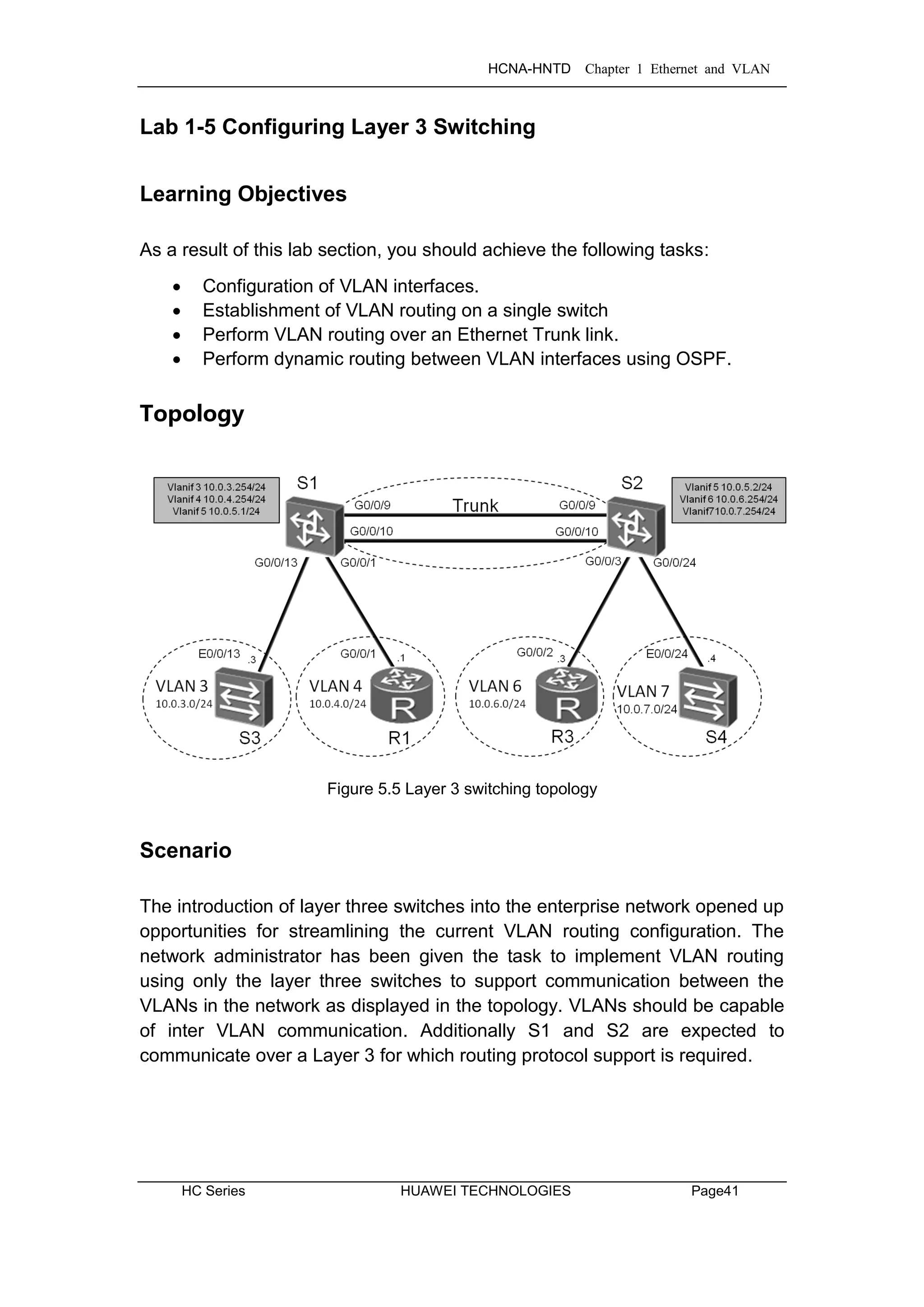
Step 8 Enable OSPF on S1 and S2.
[S1]ospf
[S1-ospf-1]area 0
[S1-ospf-1-area-0.0.0.0]network 10.0.0.0 0.255.255.255
[S2]ospf
[S2-ospf-1]area 0
[S2-ospf-1-area-0.0.0.0]network 10.0.0.0 0.255.255.255](https://image.slidesharecdn.com/hcnaintermediatelab-190422104356/75/Hcna-intermediate-lab-57-2048.jpg)
![HCNA-HNTD Chapter 1 Ethernet and VLAN
Page50 HUAWEI TECHNOLOGIES HC Series
After the configuration, wait until S1 and S2 exchange OSPF routes and
complete the link state database, then view the resulting routing table of S1.
[S1]display ip routing-table
Route Flags: R - relay, D - download to fib
----------------------------------------------------------------------------
Routing Tables: Public
Destinations : 10 Routes : 10
Destination/Mask Proto Pre Cost Flags NextHop Interface
10.0.3.0/24 Direct 0 0 D 10.0.3.254 Vlanif3
10.0.3.254/32 Direct 0 0 D 127.0.0.1 InLoopBack0
10.0.4.0/24 Direct 0 0 D 10.0.4.254 Vlanif4
10.0.4.254/32 Direct 0 0 D 127.0.0.1 InLoopBack0
10.0.5.0/24 Direct 0 0 D 10.0.5.1 Vlanif5
10.0.5.1/32 Direct 0 0 D 127.0.0.1 InLoopBack0
10.0.6.0/24 OSPF 10 2 D 10.0.5.2 Vlanif5
10.0.7.0/24 OSPF 10 2 D 10.0.5.2 Vlanif5
127.0.0.0/8 Direct 0 0 D 127.0.0.1 InLoopBack0
127.0.0.1/32 Direct 0 0 D 127.0.0.1 InLoopBack0
S1 has learned two routes using OSPF. Test connectivity between R1 and R3.
[R1]ping 10.0.6.3
PING 10.0.6.3: 56 data bytes, press CTRL_C to break
Reply from 10.0.6.3: bytes=56 Sequence=1 ttl=253 time=11 ms
Reply from 10.0.6.3: bytes=56 Sequence=2 ttl=253 time=1 ms
Reply from 10.0.6.3: bytes=56 Sequence=3 ttl=253 time=10 ms
Reply from 10.0.6.3: bytes=56 Sequence=4 ttl=253 time=1 ms
Reply from 10.0.6.3: bytes=56 Sequence=5 ttl=253 time=1 ms
--- 10.0.6.3 ping statistics ---
5 packet(s) transmitted
5 packet(s) received
0.00% packet loss
round-trip min/avg/max = 1/4/11 ms](https://image.slidesharecdn.com/hcnaintermediatelab-190422104356/75/Hcna-intermediate-lab-58-2048.jpg)
![HCNA-HNTD Chapter 1 Ethernet and VLAN
HC Series HUAWEI TECHNOLOGIES Page51
[R1]ping 10.0.7.4
PING 10.0.7.4: 56 data bytes, press CTRL_C to break
Reply from 10.0.7.4: bytes=56 Sequence=1 ttl=253 time=30 ms
Reply from 10.0.7.4: bytes=56 Sequence=2 ttl=252 time=2 ms
Reply from 10.0.7.4: bytes=56 Sequence=3 ttl=252 time=3 ms
Reply from 10.0.7.4: bytes=56 Sequence=4 ttl=252 time=2 ms
Reply from 10.0.7.4: bytes=56 Sequence=5 ttl=252 time=2 ms
--- 10.0.7.4 ping statistics ---
5 packet(s) transmitted
5 packet(s) received
0.00% packet loss
round-trip min/avg/max = 2/7/30 ms
Final Configuration
[R1]display current-configuration
[V200R003C00SPC200]
#
sysname R1
#
interface GigabitEthernet0/0/1
ip address 10.0.4.1 255.255.255.0
#
ip route-static 0.0.0.0 0.0.0.0 10.0.4.254
#
user-interface con 0
authentication-mode password
set authentication password
cipher %$%$dD#}P<HzJ;Xs%X>hOkm!,.+Iq61QK`K6tI}cc-;k_o`C.+L,%$%$
user-interface vty 0 4
#
return
[S1]display current-configuration
#
!Software Version V100R006C00SPC800
sysname S1
#
vlan batch 3 to 7
#](https://image.slidesharecdn.com/hcnaintermediatelab-190422104356/75/Hcna-intermediate-lab-59-2048.jpg)
![HCNA-HNTD Chapter 1 Ethernet and VLAN
HC Series HUAWEI TECHNOLOGIES Page53
[S2]display current-configuration
#
!Software Version V100R006C00SPC800
sysname S2
#
vlan batch 3 to 7
#
interface Vlanif5
ip address 10.0.5.2 255.255.255.0
#
interface Vlanif6
ip address 10.0.6.254 255.255.255.0
#
interface Vlanif7
ip address 10.0.7.254 255.255.255.0
#
interface Eth-Trunk1
port link-type trunk
port trunk allow-pass vlan 2 to 4094
mode lacp-static
#
interface GigabitEthernet0/0/3
port link-type access
port default vlan 6
#
interface GigabitEthernet0/0/9
eth-trunk 1
undo negotiation auto
speed 100
#
interface GigabitEthernet0/0/10
eth-trunk 1
undo negotiation auto
speed 100
#
interface GigabitEthernet0/0/24
port link-type access
port default vlan 7
#
ospf 1
area 0.0.0.0
network 10.0.0.0 0.255.255.255](https://image.slidesharecdn.com/hcnaintermediatelab-190422104356/75/Hcna-intermediate-lab-61-2048.jpg)
![HCNA-HNTD Chapter 1 Ethernet and VLAN
Page54 HUAWEI TECHNOLOGIES HC Series
#
user-interface con 0
user-interface vty 0 4
#
return
[S3]display current-configuration
#
!Software Version V100R006C00SPC800
sysname S3
#
interface Vlanif1
ip address 10.0.3.3 255.255.255.0
#
interface Ethernet0/0/23
shutdown
#
ip route-static 0.0.0.0 0.0.0.0 10.0.3.254
#
user-interface con 0
user-interface vty 0 4
#
return
[S4]display current-configuration
#
!Software Version V100R006C00SPC800
sysname S4
#
undo http server enable
#
drop illegal-mac alarm
#
aaa
authentication-scheme default
authorization-scheme default
accounting-scheme default
domain default
domain default_admin
local-user admin password simple admin
local-user admin service-type http
#](https://image.slidesharecdn.com/hcnaintermediatelab-190422104356/75/Hcna-intermediate-lab-62-2048.jpg)


![HCNA-HNTD Chapter 2 Enterprise WAN Configuration
HC Series HUAWEI TECHNOLOGIES Page57
Tasks
Step 1 Preparing the environment
If you are starting this section with a non-configured device, begin here and
then move to step 3. For those continuing from previous labs, begin at step 2.
<Huawei>system-view
Enter system view, return user view with Ctrl+Z.
[Huawei]sysname R1
<Huawei>system-view
Enter system view, return user view with Ctrl+Z.
[Huawei]sysname R2
<Huawei>system-view
Enter system view, return user view with Ctrl+Z.
[Huawei]sysname R3
Step 2 Clean up the previous configuration
Remove the static routes to R2 and disable the Ethernet interfaces to avoid
creating alternative routes. Remove any unnecessary VLAN configuration.
[R1]undo ip route-static 0.0.0.0 0
[R1]interface GigabitEthernet 0/0/1
[R1-GigabitEthernet0/0/1]shutdown
[R3]undo ip route-static 0.0.0.0 0
[R3]interface GigabitEthernet 0/0/2
[R3-GigabitEthernet0/0/2]shutdown
[S1]undo interface Vlanif 3
[S1]undo interface Vlanif 5
[S1]undo vlan batch 3 5 to 7
Warning: The configurations of the VLAN will be deleted. Continue?[Y/N]:y
Info: This operation may take a few seconds. Please wait for a moment...done.
[S1]interface GigabitEthernet 0/0/1
[S1-GigabitEthernet0/0/1]undo port default vlan
[S1-GigabitEthernet0/0/1]quit
[S1]undo ospf 1](https://image.slidesharecdn.com/hcnaintermediatelab-190422104356/75/Hcna-intermediate-lab-65-2048.jpg)
![HCNA-HNTD Chapter 2 Enterprise WAN Configuration
Page58 HUAWEI TECHNOLOGIES HC Series
[S2]undo interface Vlanif 5
[S2]undo interface Vlanif 7
[S2]undo vlan batch 3 to 5 7
Warning: The configurations of the VLAN will be deleted. Continue?[Y/N]:y
Info: This operation may take a few seconds. Please wait for a moment...done.
[S2]interface GigabitEthernet 0/0/3
[S2-GigabitEthernet0/0/3]undo port default vlan
[S2-GigabitEthernet0/0/3]quit
[S2]undo ospf 1
[S3]undo interface Vlanif 1
[S4]undo interface Vlanif 1
Step 3 Configure serial interface IP addressing for R1, R2 & R3
[R1]interface Serial 1/0/0
[R1-Serial1/0/0]ip address 10.0.12.1 24
[R2]interface Serial 1/0/0
[R2-Serial1/0/0]ip address 10.0.12.2 24
[R2-Serial1/0/0]quit
[R2]interface Serial 2/0/0
[R2-Serial2/0/0]ip address 10.0.23.2 24
[R3]interface Serial 2/0/0
[R3-Serial2/0/0]ip address 10.0.23.3 24
Step 4 Enable the HDLC protocol on the serial interfaces.
[R1]interface Serial 1/0/0
[R1-Serial1/0/0]link-protocol hdlc
Warning: The encapsulation protocol of the link will be changed. Continue? [Y/N]:y
[R2]interface Serial 1/0/0
[R2-Serial1/0/0]link-protocol hdlc
Warning: The encapsulation protocol of the link will be changed. Continue? [Y/N]:y
[R2-Serial1/0/0]quit
[R2]interface Serial 2/0/0
[R2-Serial2/0/0]link-protocol hdlc
Warning: The encapsulation protocol of the link will be changed. Continue? [Y/N]:y](https://image.slidesharecdn.com/hcnaintermediatelab-190422104356/75/Hcna-intermediate-lab-66-2048.jpg)
![HCNA-HNTD Chapter 2 Enterprise WAN Configuration
HC Series HUAWEI TECHNOLOGIES Page59
[R3]interface Serial 2/0/0
[R3-Serial2/0/0]link-protocol hdlc
Warning: The encapsulation protocol of the link will be changed. Continue? [Y/N]:y
After HDLC is enabled on the serial interfaces, view the serial interface status.
The displayed information for R1 should be used as an example.
[R1]display interface Serial1/0/0
Serial1/0/0 current state : UP
Line protocol current state : UP
Last line protocol up time : 2013-12-10 11:25:08
Description:HUAWEI, AR Series, Serial1/0/0 Interface
Route Port,The Maximum Transmit Unit is 1500, Hold timer is 10(sec)
Internet Address is 10.0.12.1/24
Link layer protocol is nonstandard HDLC
Last physical up time : 2013-12-10 11:23:55
Last physical down time : 2013-12-10 11:23:55
Current system time: 2013-12-10 11:25:46
Physical layer is synchronous, Baudrate is 64000 bps
Interface is DCE, Cable type is V24, Clock mode is DCECLK
Last 300 seconds input rate 3 bytes/sec 24 bits/sec 0 packets/sec
Last 300 seconds output rate 3 bytes/sec 24 bits/sec 0 packets/sec
Input: 100418 packets, 1606804 bytes
Broadcast: 0, Multicast: 0
Errors: 0, Runts: 0
Giants: 0, CRC: 0
Alignments: 0, Overruns: 0
Dribbles: 0, Aborts: 0
No Buffers: 0, Frame Error: 0
Output: 100418 packets, 1606830 bytes
Total Error: 0, Overruns: 0
Collisions: 0, Deferred: 0
No Buffers: 0
DCD=UP DTR=UP DSR=UP RTS=UP CTS=UP
Input bandwidth utilization : 0.06%
Output bandwidth utilization : 0.06%](https://image.slidesharecdn.com/hcnaintermediatelab-190422104356/75/Hcna-intermediate-lab-67-2048.jpg)
![HCNA-HNTD Chapter 2 Enterprise WAN Configuration
Page60 HUAWEI TECHNOLOGIES HC Series
Test connectivity of the directly connected link after verifying that the physical
status and protocol status of the interface are Up.
<R2>ping 10.0.12.1
PING 10.0.12.1: 56 data bytes, press CTRL_C to break
Reply from 10.0.12.1: bytes=56 Sequence=1 ttl=255 time=44 ms
Reply from 10.0.12.1: bytes=56 Sequence=2 ttl=255 time=39 ms
Reply from 10.0.12.1: bytes=56 Sequence=3 ttl=255 time=39 ms
Reply from 10.0.12.1: bytes=56 Sequence=4 ttl=255 time=40 ms
Reply from 10.0.12.1: bytes=56 Sequence=5 ttl=255 time=39 ms
--- 10.0.12.1 ping statistics ---
5 packet(s) transmitted
5 packet(s) received
0.00% packet loss
round-trip min/avg/max = 39/40/44 ms
[R2]ping 10.0.23.3
PING 10.0.23.3: 56 data bytes, press CTRL_C to break
Reply from 10.0.23.3: bytes=56 Sequence=1 ttl=255 time=44 ms
Reply from 10.0.23.3: bytes=56 Sequence=2 ttl=255 time=39 ms
Reply from 10.0.23.3: bytes=56 Sequence=3 ttl=255 time=39 ms
Reply from 10.0.23.3: bytes=56 Sequence=4 ttl=255 time=40 ms
Reply from 10.0.23.3: bytes=56 Sequence=5 ttl=255 time=39 ms
--- 10.0.23.3 ping statistics ---
5 packet(s) transmitted
5 packet(s) received
0.00% packet loss
round-trip min/avg/max = 39/40/44 ms
Step 5 Configure RIPv2.
Enable the RIP routing protocol to advertise the remote networks of R1 & R3
[R1]rip
[R1-rip-1]version 2
[R1-rip-1]network 10.0.0.0
[R2]rip
[R2-rip-1]version 2
[R2-rip-1]network 10.0.0.0](https://image.slidesharecdn.com/hcnaintermediatelab-190422104356/75/Hcna-intermediate-lab-68-2048.jpg)
![HCNA-HNTD Chapter 2 Enterprise WAN Configuration
HC Series HUAWEI TECHNOLOGIES Page61
[R3]rip
[R3-rip-1]version 2
[R3-rip-1]network 10.0.0.0
After the configuration is complete, check that all the routes have been learned.
Verify that corresponding routes are learned by RIP.
<R1>display ip routing-table
Route Flags: R - relay, D - download to fib
----------------------------------------------------------------------------
Routing Tables: Public
Destinations : 8 Routes : 8
Destination/Mask Proto Pre Cost Flags NextHop Interface
10.0.12.0/24 Direct 0 0 D 10.0.12.1 Serial1/0/0
10.0.12.1/32 Direct 0 0 D 127.0.0.1 Serial1/0/0
10.0.12.255/32 Direct 0 0 D 127.0.0.1 Serial1/0/0
10.0.23.0/24 RIP 100 1 D 10.0.12.2 Serial1/0/0
127.0.0.0/8 Direct 0 0 D 127.0.0.1 InLoopBack0
127.0.0.1/32 Direct 0 0 D 127.0.0.1 InLoopBack0
127.255.255.255/32 Direct 0 0 D 127.0.0.1 InLoopBack0
255.255.255.255/32 Direct 0 0 D 127.0.0.1 InLoopBack0
On R1, run the ping command to test connectivity between R1 and R3.
<R1>ping 10.0.23.3
PING 10.0.23.3: 56 data bytes, press CTRL_C to break
Reply from 10.0.23.3: bytes=56 Sequence=1 ttl=254 time=44 ms
Reply from 10.0.23.3: bytes=56 Sequence=2 ttl=254 time=39 ms
Reply from 10.0.23.3: bytes=56 Sequence=3 ttl=254 time=39 ms
Reply from 10.0.23.3: bytes=56 Sequence=4 ttl=254 time=40 ms
Reply from 10.0.23.3: bytes=56 Sequence=5 ttl=254 time=39 ms
--- 10.0.23.3 ping statistics ---
5 packet(s) transmitted
5 packet(s) received
0.00% packet loss
round-trip min/avg/max = 39/40/44 ms](https://image.slidesharecdn.com/hcnaintermediatelab-190422104356/75/Hcna-intermediate-lab-69-2048.jpg)
![HCNA-HNTD Chapter 2 Enterprise WAN Configuration
Page62 HUAWEI TECHNOLOGIES HC Series
Step 6 Manage the serial connection
View the type of the cable connected to the serial interface, interface status,
and clock frequency, and change the clock frequency.
<R1>display interface Serial1/0/0
Serial1/0/0 current state : UP
Line protocol current state : UP
Last line protocol up time : 2013-12-10 11:25:08
Description:HUAWEI, AR Series, Serial1/0/0 Interface
Route Port,The Maximum Transmit Unit is 1500, Hold timer is 10(sec)
Internet Address is 10.0.12.1/24
Link layer protocol is nonstandard HDLC
Last physical up time : 2013-12-10 11:23:55
Last physical down time : 2013-12-10 11:23:55
Current system time: 2013-12-10 11:51:12
Physical layer is synchronous, Baudrate is 64000 bps
Interface is DCE, Cable type is V24, Clock mode is DCECLK
Last 300 seconds input rate 6 bytes/sec 48 bits/sec 0 packets/sec
Last 300 seconds output rate 4 bytes/sec 32 bits/sec 0 packets/sec
…output omitted…
The preceding information shows that S1/0/0 on R1 connects to a DCE cable
and the clock frequency is 64000 bit/s. The DCE controls the clock frequency
and bandwidth.
Change the clock frequency on the link between R1 and R2 to 128000 bit/s.
This operation must be performed on the DCE, R1.
[R1]interface Serial 1/0/0
[R1-Serial1/0/0]baudrate 128000
After the configuration is complete, view the serial interface status.
<R1>display interface Serial1/0/0
Serial1/0/0 current state : UP
Line protocol current state : UP
Last line protocol up time : 2013-12-10 11:25:08
Description:HUAWEI, AR Series, Serial1/0/0 Interface
Route Port,The Maximum Transmit Unit is 1500, Hold timer is 10(sec)
Internet Address is 10.0.12.1/24
Link layer protocol is nonstandard HDLC
Last physical up time : 2013-12-10 11:23:55
Last physical down time : 2013-12-10 11:23:55](https://image.slidesharecdn.com/hcnaintermediatelab-190422104356/75/Hcna-intermediate-lab-70-2048.jpg)
![HCNA-HNTD Chapter 2 Enterprise WAN Configuration
HC Series HUAWEI TECHNOLOGIES Page63
Current system time: 2013-12-10 11:54:19
Physical layer is synchronous, Baudrate is 128000 bps
Interface is DCE, Cable type is V24, Clock mode is DCECLK
Last 300 seconds input rate 6 bytes/sec 48 bits/sec 0 packets/sec
Last 300 seconds output rate 4 bytes/sec 32 bits/sec 0 packets/sec
…output omitted…
Step 7 Configure PPP on the serial interfaces.
Configure PPP between R1 and R2, as well as R2 and R3. Both ends of the
link must use the same encapsulation mode. If different encapsulation modes
are used, interfaces may display as ‘Down’.
[R1]interface Serial 1/0/0
[R1-Serial1/0/0]link-protocol ppp
Warning: The encapsulation protocol of the link will be changed. Continue? [Y/N]:y
[R2]interface Serial 1/0/0
[R2-Serial1/0/0]link-protocol ppp
Warning: The encapsulation protocol of the link will be changed. Continue? [Y/N]:y
[R2-Serial1/0/0]quit
[R2]interface Serial 2/0/0
[R2-Serial2/0/0]link-protocol ppp
Warning: The encapsulation protocol of the link will be changed. Continue? [Y/N]:y
[R3]interface Serial 2/0/0
[R3-Serial2/0/0]link-protocol ppp
Warning: The encapsulation protocol of the link will be changed. Continue? [Y/N]:y
After the configuration is complete, test link connectivity.
<R2>ping 10.0.12.1
PING 10.0.12.1: 56 data bytes, press CTRL_C to break
Reply from 10.0.12.1: bytes=56 Sequence=1 ttl=255 time=22 ms
Reply from 10.0.12.1: bytes=56 Sequence=2 ttl=255 time=27 ms
Reply from 10.0.12.1: bytes=56 Sequence=3 ttl=255 time=27 ms
Reply from 10.0.12.1: bytes=56 Sequence=4 ttl=255 time=27 ms
Reply from 10.0.12.1: bytes=56 Sequence=5 ttl=255 time=27 ms
--- 10.0.12.1 ping statistics ---
5 packet(s) transmitted
5 packet(s) received
0.00% packet loss
round-trip min/avg/max = 22/26/27 ms](https://image.slidesharecdn.com/hcnaintermediatelab-190422104356/75/Hcna-intermediate-lab-71-2048.jpg)

![HCNA-HNTD Chapter 2 Enterprise WAN Configuration
HC Series HUAWEI TECHNOLOGIES Page65
The following information uses R2 as an example, for which the routes to R1
and R3 can be seen.
[R2]display ip routing-table
Route Flags: R - relay, D - download to fib
----------------------------------------------------------------------------
Routing Tables: Public
Destinations : 12 Routes : 12
Destination/Mask Proto Pre Cost Flags NextHop Interface
10.0.12.0/24 Direct 0 0 D 10.0.12.2 Serial1/0/0
10.0.12.1/32 Direct 0 0 D 10.0.12.1 Serial1/0/0
10.0.12.2/32 Direct 0 0 D 127.0.0.1 Serial1/0/0
10.0.12.255/32 Direct 0 0 D 127.0.0.1 Serial1/0/0
10.0.23.0/24 Direct 0 0 D 10.0.23.2 Serial2/0/0
10.0.23.2/32 Direct 0 0 D 127.0.0.1 Serial2/0/0
10.0.23.3/32 Direct 0 0 D 10.0.23.3 Serial2/0/0
10.0.23.255/32 Direct 0 0 D 127.0.0.1 Serial2/0/0
127.0.0.0/8 Direct 0 0 D 127.0.0.1 InLoopBack0
127.0.0.1/32 Direct 0 0 D 127.0.0.1 InLoopBack0
127.255.255.255/32 Direct 0 0 D 127.0.0.1 InLoopBack0
255.255.255.255/32 Direct 0 0 D 127.0.0.1 InLoopBack0
Think about the origin and functions of the two routes. Check the following
items:
If HDLC encapsulation is used, do these two routes exist?
Can R1 and R2 communicate using HDLC or PPP when the IP addresses of
S1/0/0 interfaces on R1 and R2 are located on different network segments?
Step 9 Enable PAP authentication between R1 and R2.
Configure PAP authentication with R1 as the PPP PAP authenticator.
[R1]interface Serial 1/0/0
[R1-Serial1/0/0]ppp authentication-mode pap
[R1-Serial1/0/0]quit
[R1]aaa
[R1-aaa]local-user huawei password cipher huawei
info: A new user added
[R1-aaa]local-user huawei service-type ppp](https://image.slidesharecdn.com/hcnaintermediatelab-190422104356/75/Hcna-intermediate-lab-73-2048.jpg)
![HCNA-HNTD Chapter 2 Enterprise WAN Configuration
Page66 HUAWEI TECHNOLOGIES HC Series
Configure PAP authentication with R2 acting as the PAP authenticated device.
[R2]interface Serial 1/0/0
[R2-Serial1/0/0]ppp pap local-user huawei password cipher huawei
After R2 sends an authentication request to R1, R1 sends a response
message to R2, requesting R2 to use PAP authentication following which R2
will send its password to R1.
After the configuration is complete, test connectivity between R1 and R2.
<R1>debugging ppp pap packet
<R1>terminal debugging
<R1>display debugging
PPP PAP packets debugging switch is on
<R1>system-view
[R1]interface Serial 1/0/0
[R1-Serial1/0/0]shutdown
[R1-Serial1/0/0]undo shutdown
Dec 10 2013 14:44:22.440.1+00:00 R1 PPP/7/debug2:
PPP Packet:
Serial1/0/0 Input PAP(c023) Pkt, Len 22
State ServerListen, code Request(01), id 1, len 18
Host Len: 6 Name:huawei
[R1-Serial1/0/0]
Dec 10 2013 14:44:22.440.2+00:00 R1 PPP/7/debug2:
PPP Packet:
Serial1/0/0 Output PAP(c023) Pkt, Len 52
State WaitAAA, code Ack(02), id 1, len 48
Msg Len: 43 Msg:Welcome to use Quidway ROUTER, Huawei Tech.
[R1-Serial1/0/0]return
<R1>undo debugging all
Info: All possible debugging has been turned off
Step 10 Enable CHAP authentication between R2 and R3.
Configure R3 as the authenticator. After R2 sends an authentication request to
R3, R3 sends a response message to R2, requesting R2 to use CHAP
authentication following which a challenge is sent to R3.](https://image.slidesharecdn.com/hcnaintermediatelab-190422104356/75/Hcna-intermediate-lab-74-2048.jpg)
![HCNA-HNTD Chapter 2 Enterprise WAN Configuration
HC Series HUAWEI TECHNOLOGIES Page67
[R3]interface Serial 2/0/0
[R3-Serial2/0/0]ppp authentication-mode chap
[R3-Serial2/0/0]quit
[R3]aaa
[R3-aaa]local-user huawei password cipher huawei
info: A new user added
[R3-aaa]local-user huawei service-type ppp
[R3-aaa]quit
[R3]interface Serial 2/0/0
[R3-Serial2/0/0]shutdown
[R3-Serial2/0/0]undo shutdown
On R3, the following information is displayed.
Dec 10 2013 15:06:00+00:00 R3 %%01PPP/4/PEERNOCHAP(l)[5]:On the interface
Serial2/0/0, authentication failed and PPP link was closed because CHAP was
disabled on the peer.
[R3-Serial2/0/0]
Dec 10 2013 15:06:00+00:00 R3 %%01PPP/4/RESULTERR(l)[6]:On the interface
Serial2/0/0, LCP negotiation failed because the result cannot be accepted.
The highlighted output indicates that authentication is unable to initialize.
Configure R2 as the CHAP client.
[R2]interface Serial 2/0/0
[R2-Serial2/0/0]ppp chap user huawei
[R2-Serial2/0/0]ppp chap password cipher huawei
After the configuration is complete, the interface changes to an Up state. The
ping command output is as follows:
<R2>ping 10.0.23.3
PING 10.0.23.3: 56 data bytes, press CTRL_C to break
Reply from 10.0.23.3: bytes=56 Sequence=1 ttl=255 time=35 ms
Reply from 10.0.23.3: bytes=56 Sequence=2 ttl=255 time=41 ms
Reply from 10.0.23.3: bytes=56 Sequence=3 ttl=255 time=41 ms
Reply from 10.0.23.3: bytes=56 Sequence=4 ttl=255 time=41 ms
Reply from 10.0.23.3: bytes=56 Sequence=5 ttl=255 time=41 ms
--- 10.0.23.3 ping statistics ---
5 packet(s) transmitted
5 packet(s) received
0.00% packet loss
round-trip min/avg/max = 35/39/41 ms](https://image.slidesharecdn.com/hcnaintermediatelab-190422104356/75/Hcna-intermediate-lab-75-2048.jpg)
![HCNA-HNTD Chapter 2 Enterprise WAN Configuration
Page68 HUAWEI TECHNOLOGIES HC Series
Step 11 PPP CHAP debugging
Run the debug command to view negotiation of the PPP connection between
R2 and R3. The PPP connection is established using CHAP. Disable interface
Serial 2/0/0 on R2, run the debug command, and enable Serial 2/0/0 on R2.
[R2]interface Serial 2/0/0
[R2-Serial2/0/0]shutdown
Run the debugging ppp chap all and the terminal debugging commands to
display the debugging information.
[R2-Serial2/0/0]return
<R2>debugging ppp chap all
<R2>terminal debugging
Info: Current terminal debugging is on.
<R2>display debugging
PPP CHAP packets debugging switch is on
PPP CHAP events debugging switch is on
PPP CHAP errors debugging switch is on
PPP CHAP state change debugging switch is on
Force CHAP authentication to initialize on S2/0/0 of R2.
<R2>system-view
Enter system view, return user view with Ctrl+Z.
[R2]interface Serial 2/0/0
[R2-Serial2/0/0]undo shutdown
The following debugging information is displayed:
Dec 10 2013 09:10:38.700.1+00:00 R2 PPP/7/debug2:
PPP State Change:
Serial2/0/0 CHAP : Initial --> ListenChallenge
[R2-Serial2/0/0]
Dec 10 2013 09:10:38.710.1+00:00 R2 PPP/7/debug2:
PPP Packet:
Serial2/0/0 Input CHAP(c223) Pkt, Len 25
State ListenChallenge, code Challenge(01), id 1, len 21
Value_Size: 16 Value: fc 9b 56 e1 53 e3 a6 26 1b 54 e5 e2 a1 ed 90 87
Name:
[R2-Serial2/0/0]
Dec 10 2013 09:10:38.710.2+00:00 R2 PPP/7/debug2:
PPP Event:](https://image.slidesharecdn.com/hcnaintermediatelab-190422104356/75/Hcna-intermediate-lab-76-2048.jpg)
![HCNA-HNTD Chapter 2 Enterprise WAN Configuration
HC Series HUAWEI TECHNOLOGIES Page69
Serial2/0/0 CHAP Receive Challenge Event
state ListenChallenge
[R2-Serial2/0/0]
Dec 10 2013 09:10:38.710.3+00:00 R2 PPP/7/debug2:
PPP Packet:
Serial2/0/0 Output CHAP(c223) Pkt, Len 31
State ListenChallenge, code Response(02), id 1, len 27
Value_Size: 16 Value: f9 54 1 69 30 59 a0 af 52 a1 1d de 85 77 27 6b
Name: huawei
[R2-Serial2/0/0]
Dec 10 2013 09:10:38.710.4+00:00 R2 PPP/7/debug2:
PPP State Change:
Serial2/0/0 CHAP : ListenChallenge --> SendResponse
[R2-Serial2/0/0]
Dec 10 2013 09:10:38.720.1+00:00 R2 PPP/7/debug2:
PPP Packet:
Serial2/0/0 Input CHAP(c223) Pkt, Len 20
State SendResponse, code SUCCESS(03), id 1, len 16
Message: Welcome to .
[R2-Serial2/0/0]
Dec 10 2013 09:10:38.720.2+00:00 R2 PPP/7/debug2:
PPP Event:
Serial2/0/0 CHAP Receive Success Event
state SendResponse
[R2-Serial2/0/0]
Dec 10 2013 09:10:38.720.3+00:00 R2 PPP/7/debug2:
PPP State Change:
Serial2/0/0 CHAP : SendResponse --> ClientSuccess
The highlighted debugging information shows the key CHAP behavior. Disable
the debugging process.
[R2-Serial2/0/0]return
<R2>undo debugging all
Info: All possible debugging has been turned off
Additional Exercises: Analyzing and Verifying
Why is the PPP Challenge Handshake Authentication Protocol (CHAP) more
secure than the PPP Password Authentication Protocol (PAP)?](https://image.slidesharecdn.com/hcnaintermediatelab-190422104356/75/Hcna-intermediate-lab-77-2048.jpg)
![HCNA-HNTD Chapter 2 Enterprise WAN Configuration
Page70 HUAWEI TECHNOLOGIES HC Series
Final Configuration
[R1]display current-configuration
[V200R003C00SPC200]
#
sysname R1
#
aaa
authentication-scheme default
authorization-scheme default
accounting-scheme default
domain default
domain default_admin
local-user admin password cipher %$%$=i~>Xp&aY+*2cEVcS-A23Uwe%$%$
local-user admin service-type http
local-user huawei password cipher %$%$B:%I)Io0H8)[%SB[idM3C/!#%$%$
local-user huawei service-type ppp
#
interface Serial1/0/0
link-protocol ppp
ppp authentication-mode pap
ip address 10.0.12.1 255.255.255.0
baudrate 128000
#
rip 1
version 2
network 10.0.0.0
#
user-interface con 0
authentication-mode password
set authentication password
cipher %$%$dD#}P<HzJ;Xs%X>hOkm!,.+Iq61QK`K6tI}cc-;k_o`C.+L,%$%$
user-interface vty 0 4
#
return
[R2]display current-configuration
[V200R003C00SPC200]
#
sysname R2
#](https://image.slidesharecdn.com/hcnaintermediatelab-190422104356/75/Hcna-intermediate-lab-78-2048.jpg)
![HCNA-HNTD Chapter 2 Enterprise WAN Configuration
HC Series HUAWEI TECHNOLOGIES Page71
interface Serial1/0/0
link-protocol ppp
ppp pap local-user huawei password cipher %$%$u[hr6d<JVHR@->T7xr1<$.iv%$%$
ip address 10.0.12.2 255.255.255.0
#
interface Serial2/0/0
link-protocol ppp
ppp chap user huawei
ppp chap password cipher %$%$e{5h)gh"/Uz0mUC%vEx3$4<m%$%$
ip address 10.0.23.2 255.255.255.0
#
rip 1
version 2
network 10.0.0.0
#
user-interface con 0
authentication-mode password
set authentication password
cipher %$%$|nRPL^hr2IXi7LHDID!/,.*%.8%h;3:,hXO2dk#ikaWI.*(,%$%$
user-interface vty 0 4
#
return
[R3]display current-configuration
[V200R003C00SPC200]
#
sysname R3
#
aaa
authentication-scheme default
authorization-scheme default
accounting-scheme default
domain default
domain default_admin
local-user admin password cipher %$%$=i~>Xp&aY+*2cEVcS-A23Uwe%$%$
local-user admin service-type http
local-user huawei password cipher %$%$fZsyUk1=O=>:L4'ytgR~D*Im%$%$
local-user huawei service-type ppp
#
interface Serial2/0/0
link-protocol ppp
ppp authentication-mode chap](https://image.slidesharecdn.com/hcnaintermediatelab-190422104356/75/Hcna-intermediate-lab-79-2048.jpg)
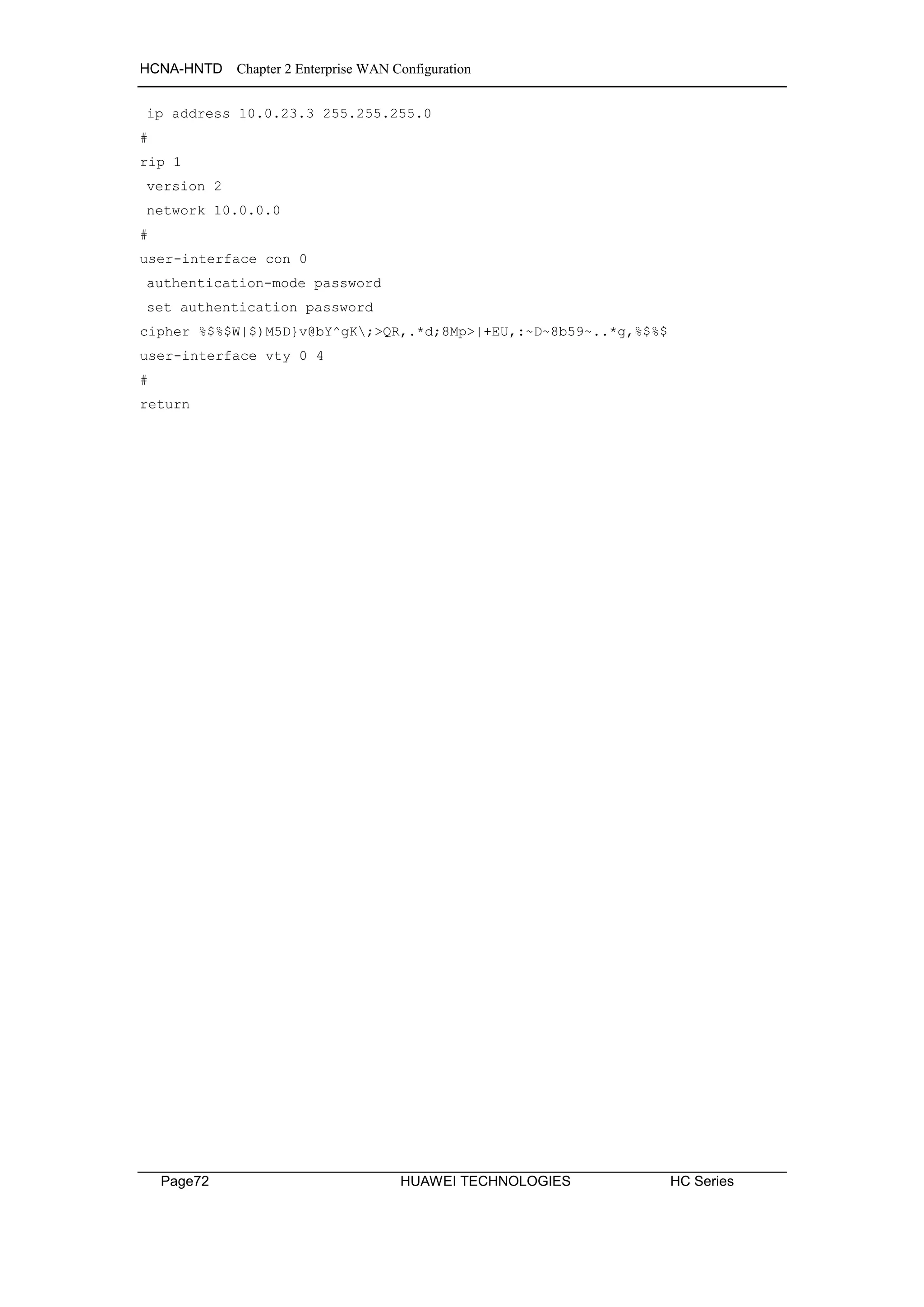
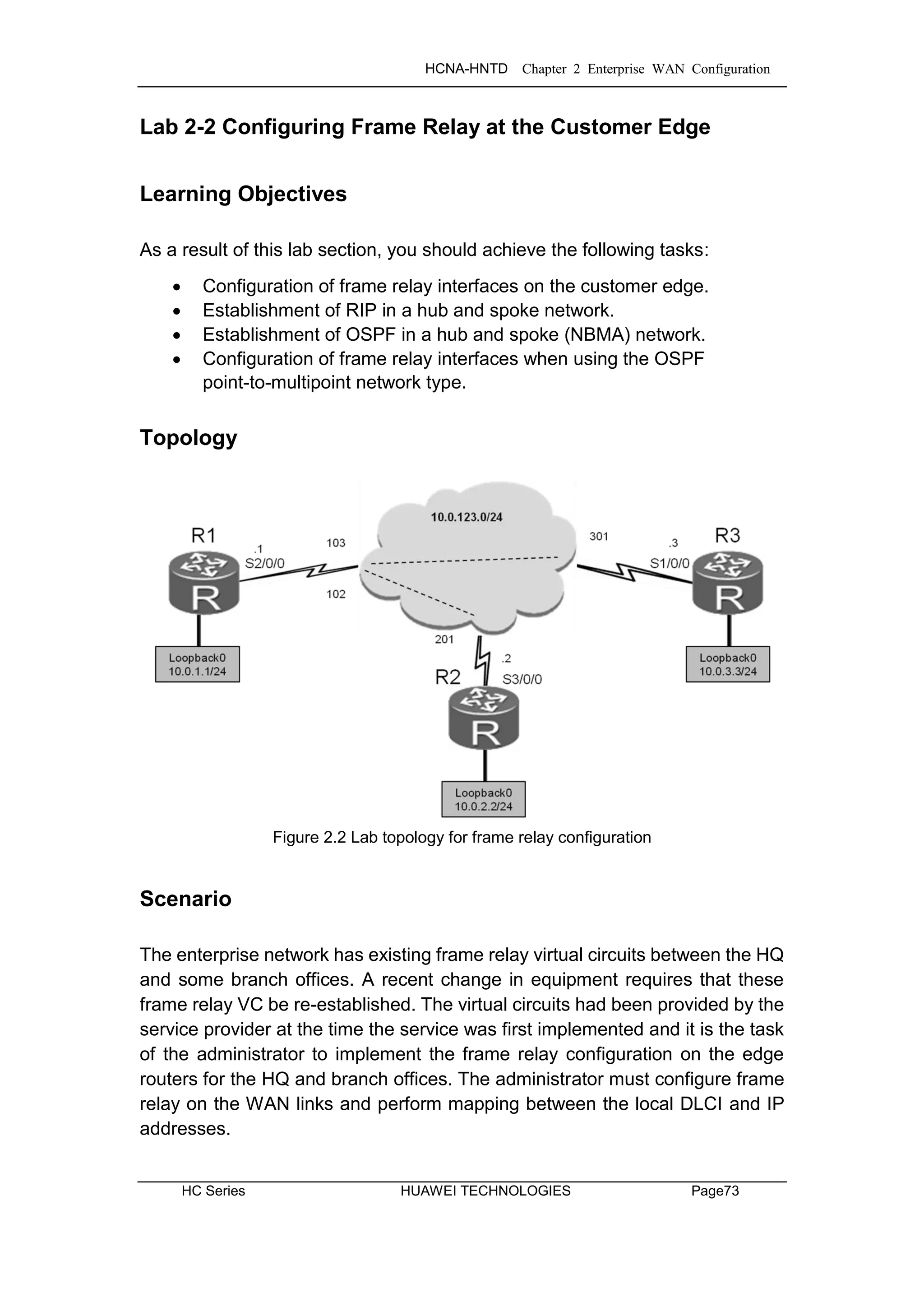
![HCNA-HNTD Chapter 2 Enterprise WAN Configuration
Page74 HUAWEI TECHNOLOGIES HC Series
Tasks
Step 1 Preparing the environment
If you are starting this section with a non-configured device, begin here and
then move to step 3. For those continuing from previous labs, begin at step 2.
<Huawei>system-view
Enter system view, return user view with Ctrl+Z.
[Huawei]sysname R1
<Huawei>system-view
Enter system view, return user view with Ctrl+Z.
[Huawei]sysname R2
<Huawei>system-view
Enter system view, return user view with Ctrl+Z.
[Huawei]sysname R3
Step 2 Clean up the previous configuration.
Disable the serial interfaces used for establishing the HDLC & PPP networks.
[R1]interface Serial 1/0/0
[R1-Serial1/0/0]shutdown
[R2]interface Serial 1/0/0
[R2-Serial1/0/0]shutdown
[R2-Serial1/0/0]interface Serial 2/0/0
[R2-Serial2/0/0]shutdown
[R3]interface Serial 2/0/0
[R3-Serial2/0/0]shutdown
Step 3 Establish frame relay encapsulation.
Set basic parameters, including IP addresses. Manually define the mapping
between the peer and DLCI. The inverse ARP function should be disabled.
Ensure that the broadcast parameter is used in the fr map command to allow
the network on the loopback interface to be advertised using RIP.](https://image.slidesharecdn.com/hcnaintermediatelab-190422104356/75/Hcna-intermediate-lab-82-2048.jpg)
![HCNA-HNTD Chapter 2 Enterprise WAN Configuration
HC Series HUAWEI TECHNOLOGIES Page75
[R1]interface Serial 2/0/0
[R1-Serial2/0/0]link-protocol fr
Warning: The encapsulation protocol of the link will be changed. Continue? [Y/N]:y
[R1-Serial2/0/0]ip address 10.0.123.1 24
[R1-Serial2/0/0]undo fr inarp
[R1-Serial2/0/0]fr map ip 10.0.123.2 102 broadcast
[R1-Serial2/0/0]fr map ip 10.0.123.3 103 broadcast
[R1-Serial2/0/0]interface loopback 0
[R1-LoopBack0]ip address 10.0.1.1 24
[R2]interface Serial 3/0/0
[R2-Serial3/0/0]link-protocol fr
Warning: The encapsulation protocol of the link will be changed. Continue? [Y/N]:y
[R2-Serial3/0/0]ip address 10.0.123.2 24
[R2-Serial3/0/0]undo fr inarp
[R2-Serial3/0/0]fr map ip 10.0.123.1 201 broadcast
[R2-Serial3/0/0]interface loopback 0
[R2-LoopBack0]ip address 10.0.2.2 24
[R3]interface Serial 1/0/0
[R3-Serial1/0/0]link-protocol fr
Warning: The encapsulation protocol of the link will be changed. Continue? [Y/N]:y
[R3-Serial1/0/0]ip address 10.0.123.3 24
[R3-Serial1/0/0]undo fr inarp
[R3-Serial1/0/0]fr map ip 10.0.123.1 301 broadcast
[R3-Serial1/0/0]interface loopback 0
[R3-LoopBack0]ip address 10.0.3.3 24
After the IP addresses are configured, test network connectivity.
<R1>ping 10.0.123.2
PING 10.0.123.2: 56 data bytes, press CTRL_C to break
Reply from 10.0.123.2: bytes=56 Sequence=1 ttl=255 time=64 ms
Reply from 10.0.123.2: bytes=56 Sequence=2 ttl=255 time=59 ms
Reply from 10.0.123.2: bytes=56 Sequence=3 ttl=255 time=59 ms
Reply from 10.0.123.2: bytes=56 Sequence=4 ttl=255 time=59 ms
Reply from 10.0.123.2: bytes=56 Sequence=5 ttl=255 time=59 ms
--- 10.0.123.2 ping statistics ---
5 packet(s) transmitted
5 packet(s) received
0.00% packet loss
round-trip min/avg/max = 59/60/64 ms](https://image.slidesharecdn.com/hcnaintermediatelab-190422104356/75/Hcna-intermediate-lab-83-2048.jpg)
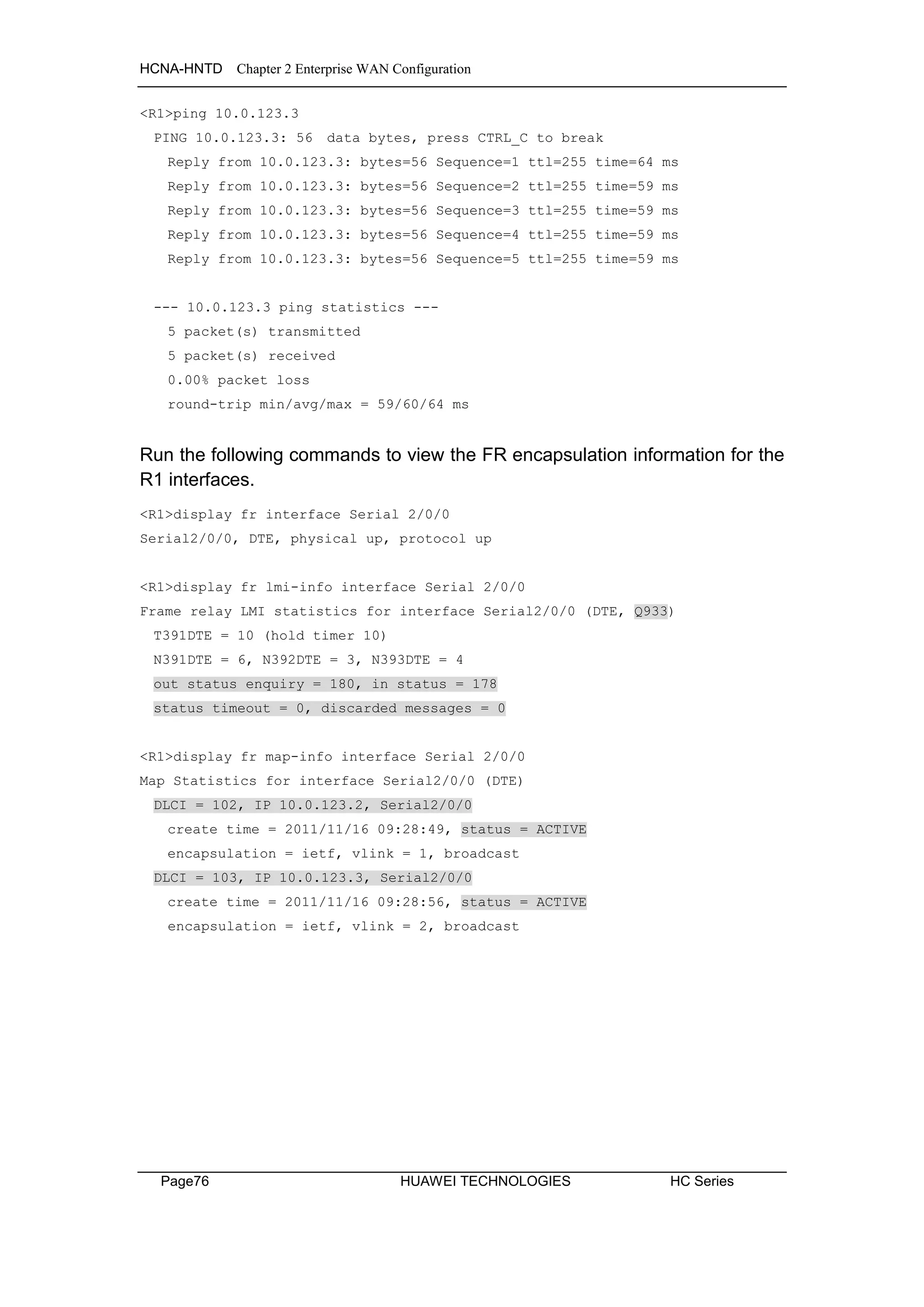
![HCNA-HNTD Chapter 2 Enterprise WAN Configuration
HC Series HUAWEI TECHNOLOGIES Page77
Step 4 Configure RIPv2 between R1, R2, and R3.
Configure RIPv2 on R1, R2 and R3. If you are continuing from the previous
HDLC/PPP lab, the RIP routes for network 10.0.0.0 may have already been
configured, however the automatic summary must still be disabled to uniquely
identify the routes of the peers.
In addition, split horizon is disabled by default on frame relay networks, and so
It is not necessary for the split horizon parameters to be modified in this
exercise.
[R1]rip 1
[R1-rip-1]version 2
[R1-rip-1]network 10.0.0.0
[R1-rip-1]undo summary
[R2]rip 1
[R2-rip-1]version 2
[R2-rip-1]network 10.0.0.0
[R2-rip-1]undo summary
[R3]rip 1
[R3-rip-1]version 2
[R3-rip-1]network 10.0.0.0
[R3-rip-1]undo summary
View the routing tables on R1, R2, and R3 to check the learned routes.
<R1>display ip routing-table protocol rip
Route Flags: R - relay, D - download to fib
----------------------------------------------------------------------------
Public routing table : RIP
Destinations : 2 Routes : 2
RIP routing table status : <Active>
Destinations : 2 Routes : 2
Destination/Mask Proto Pre Cost Flags NextHop Interface
10.0.2.0/24 RIP 100 1 D 10.0.123.2 Serial2/0/0
10.0.3.0/24 RIP 100 1 D 10.0.123.3 Serial2/0/0
RIP routing table status : <Inactive>
Destinations : 0 Routes : 0](https://image.slidesharecdn.com/hcnaintermediatelab-190422104356/75/Hcna-intermediate-lab-85-2048.jpg)
![HCNA-HNTD Chapter 2 Enterprise WAN Configuration
Page78 HUAWEI TECHNOLOGIES HC Series
<R2>display ip routing-table protocol rip
Route Flags: R - relay, D - download to fib
----------------------------------------------------------------------------
Public routing table : RIP
Destinations : 2 Routes : 2
RIP routing table status : <Active>
Destinations : 2 Routes : 2
Destination/Mask Proto Pre Cost Flags NextHop Interface
10.0.1.0/24 RIP 100 1 D 10.0.123.1 Serial3/0/0
10.0.3.0/24 RIP 100 2 D 10.0.123.1 Serial3/0/0
RIP routing table status : <Inactive>
Destinations : 0 Routes : 0
[R3]display ip routing-table protocol rip
Route Flags: R - relay, D - download to fib
----------------------------------------------------------------------------
Public routing table : RIP
Destinations : 2 Routes : 2
RIP routing table status : <Active>
Destinations : 2 Routes : 2
Destination/Mask Proto Pre Cost Flags NextHop Interface
10.0.1.0/24 RIP 100 1 D 10.0.123.1 Serial1/0/0
10.0.2.0/24 RIP 100 2 D 10.0.123.1 Serial1/0/0
RIP routing table status : <Inactive>
Destinations : 0 Routes : 0](https://image.slidesharecdn.com/hcnaintermediatelab-190422104356/75/Hcna-intermediate-lab-86-2048.jpg)
![HCNA-HNTD Chapter 2 Enterprise WAN Configuration
HC Series HUAWEI TECHNOLOGIES Page79
Verify that the 10.0.3.0 network of R3 is capable of reaching the 10.0.1.0
network of R1.
[R3]ping –a 10.0.3.3 10.0.1.1
PING 10.0.1.1: 56 data bytes, press CTRL_C to break
Reply from 10.0.1.1: bytes=56 Sequence=1 ttl=255 time=68 ms
Reply from 10.0.1.1: bytes=56 Sequence=2 ttl=255 time=63 ms
Reply from 10.0.1.1: bytes=56 Sequence=3 ttl=255 time=63 ms
Reply from 10.0.1.1: bytes=56 Sequence=4 ttl=255 time=63 ms
Reply from 10.0.1.1: bytes=56 Sequence=5 ttl=255 time=63 ms
--- 10.0.1.1 ping statistics ---
5 packet(s) transmitted
5 packet(s) received
0.00% packet loss
round-trip min/avg/max = 63/64/68 ms
Perform the same test to network 10.0.2.2 of R2 from network 10.0.3.3 of R3.
<R3>ping -a 10.0.3.3 10.0.2.2
PING 10.0.2.2: 56 data bytes, press CTRL_C to break
Reply from 10.0.2.2: bytes=56 Sequence=1 ttl=254 time=101 ms
Reply from 10.0.2.2: bytes=56 Sequence=2 ttl=254 time=110 ms
Reply from 10.0.2.2: bytes=56 Sequence=3 ttl=254 time=101 ms
Reply from 10.0.2.2: bytes=56 Sequence=4 ttl=254 time=101 ms
Reply from 10.0.2.2: bytes=56 Sequence=5 ttl=254 time=101 ms
--- 10.0.2.2 ping statistics ---
5 packet(s) transmitted
5 packet(s) received
0.00% packet loss
round-trip min/avg/max = 101/102/110 ms
The RIP routing protocol has enabled a route between the loopback interfaces
of R2 and R3 to be established via R1.](https://image.slidesharecdn.com/hcnaintermediatelab-190422104356/75/Hcna-intermediate-lab-87-2048.jpg)
![HCNA-HNTD Chapter 2 Enterprise WAN Configuration
Page80 HUAWEI TECHNOLOGIES HC Series
Attempt the same procedure to network 10.0.2.2 of R2 from the S2/0/0
(10.0.123.3) interface of R3.
[R3]ping 10.0.2.2
PING 10.0.2.2: 56 data bytes, press CTRL_C to break
Request time out
Request time out
Request time out
Request time out
Request time out
--- 10.0.2.2 ping statistics ---
5 packet(s) transmitted
0 packet(s) received
100.00% packet loss
The preceding test results indicate that R3 is unable to communicate with R2
(and vice versa) when the serial interface is the source. Check the routes to
find out why R3 and R2 are disconnected. The procedure for diagnosing this
fault is as follows:
View the R3 routing table and check whether any route is destined for the IP
address 10.0.2.2.
If there is such a route, find out the next hop IP address of this route. Then
check whether R3 can reach the next hop and whether there is mapping
between the layer-3 IP addresses and layer-2 PVCs.
If R3 can reach the next hop and there is mapping between Layer-3 IP
addresses and Layer-2 PVCs, check the devices on the route to determine
whether there is any route that can reach IP address 10.0.2.2, whether the
next hop of this route is reachable, and whether there is mapping between
Layer-3 IP addresses and Layer-2 PVCs.
If there is a route that can reach IP address 10.0.2.2 and there is mapping
between Layer-3 IP addresses and Layer-2 PVCs, check R2 to determine
whether there is any route that reaches the destination IP address of the
response packets and whether the next hop of this route is reachable.
If the next hop of this route is unreachable and the destination IP address of
the response packets is 10.0.123.3, R2 has the route that reaches this address
but there is no mapping between Layer-3 IP addresses and Layer-2 PVCs.
The following is the output of the commands used in the preceding fault
diagnosis procedure.](https://image.slidesharecdn.com/hcnaintermediatelab-190422104356/75/Hcna-intermediate-lab-88-2048.jpg)


![HCNA-HNTD Chapter 2 Enterprise WAN Configuration
HC Series HUAWEI TECHNOLOGIES Page83
<R2>display fr map-info interface Serial 3/0/0
Map Statistics for interface Serial3/0/0 (DTE)
DLCI = 201, IP 10.0.123.1, Serial3/0/0
create time = 2011/11/16 09:21:10, status = ACTIVE
encapsulation = ietf, vlink = 1, broadcast
The conclusion is that there is no PVC that allows R2 to reach IP address
10.0.123.3.
Step 5 Modify network parameters to enable the connection
between R2 and R3.
The fault diagnosis results from step 2 indicate that communication fails since
there is no virtual circuit between the frame relay interfaces on R2 and R3. In
order to resolve this, configure a frame relay PVC between the interfaces on
R2 and R3.
[R2]interface Serial 3/0/0
[R2-Serial3/0/0]fr map ip 10.0.123.3 201
[R3]interface Serial 1/0/0
[R3-Serial1/0/0]fr map ip 10.0.123.2 301
After the mapping has been configured between IP addresses and PVCs,
check the IP address-PVC mapping tables on R2 and R3 and detect network
connectivity.
<R3>display fr lmi-info inter Serial 1/0/0
Frame relay LMI statistics for interface Serial1/0/0 (DTE, Q933)
T391DTE = 10 (hold timer 10)
N391DTE = 6, N392DTE = 3, N393DTE = 4
out status enquiry = 326, in status = 324
status timeout = 0, discarded messages = 0
<R3>display fr map-info interface Serial 1/0/0
Map Statistics for interface Serial1/0/0 (DTE)
DLCI = 301, IP 10.0.123.1, Serial1/0/0
create time = 2011/11/16 09:22:30, status = ACTIVE
encapsulation = ietf, vlink = 1, broadcast
DLCI = 301, IP 10.0.123.2, Serial1/0/0
create time = 2011/11/16 09:55:23, status = ACTIVE
encapsulation = ietf, vlink = 2](https://image.slidesharecdn.com/hcnaintermediatelab-190422104356/75/Hcna-intermediate-lab-91-2048.jpg)
![HCNA-HNTD Chapter 2 Enterprise WAN Configuration
Page84 HUAWEI TECHNOLOGIES HC Series
<R3>ping 10.0.2.2
PING 10.0.2.2: 56 data bytes, press CTRL_C to break
Reply from 10.0.2.2: bytes=56 Sequence=1 ttl=254 time=118 ms
Reply from 10.0.2.2: bytes=56 Sequence=2 ttl=254 time=123 ms
Reply from 10.0.2.2: bytes=56 Sequence=3 ttl=254 time=123 ms
Reply from 10.0.2.2: bytes=56 Sequence=4 ttl=254 time=123 ms
Reply from 10.0.2.2: bytes=56 Sequence=5 ttl=254 time=123 ms
--- 10.0.2.2 ping statistics ---
5 packet(s) transmitted
5 packet(s) received
0.00% packet loss
round-trip min/avg/max = 118/122/123 ms
Step 6 Configure OSPF between R1 and R2.
Delete the RIP configurations referenced in step 2 and the frame relay
mapping between R2 and R3 that was established during step 3.
[R1]undo rip 1
Warning: The RIP process will be deleted. Continue?[Y/N]y
[R2]interface Serial 3/0/0
[R2-Serial3/0/0]undo fr map ip 10.0.123.3 201
[R2-Serial3/0/0]quit
[R2]undo rip 1
Warning: The RIP process will be deleted. Continue?[Y/N]y
[R3]interface Serial 1/0/0
[R3-Serial1/0/0]undo fr map ip 10.0.123.2 301
[R3-Serial1/0/0]quit
[R3]undo rip 1
Warning: The RIP process will be deleted. Continue?[Y/N]y
[R3]
Configure single-area OSPF on R1, R2, and R3.
[R1]ospf 1 router-id 10.0.1.1
[R1-ospf-1]area 0
[R1-ospf-1-area-0.0.0.0]network 10.0.0.0 0.255.255.255](https://image.slidesharecdn.com/hcnaintermediatelab-190422104356/75/Hcna-intermediate-lab-92-2048.jpg)
![HCNA-HNTD Chapter 2 Enterprise WAN Configuration
HC Series HUAWEI TECHNOLOGIES Page85
[R2]ospf 1 router-id 10.0.2.2
[R2-ospf-1]area 0
[R2-ospf-1-area-0.0.0.0]network 10.0.0.0 0.255.255.255
[R3]ospf 1 router-id 10.0.3.3
[R3-ospf-1]area 0
[R3-ospf-1-area-0.0.0.0]network 10.0.0.0 0.255.255.255
After the basic parameters are set, OSPF cannot establish neighbor
adjacencies. When using frame relay for data link layer encapsulation, OSPF
will set the network type to NBMA by default. As a result, OSPF does not
support broadcasts, and therefore cannot automatically discover neighbors.
<R3>display ospf interface Serial 1/0/0 verbose
OSPF Process 1 with Router ID 10.0.3.3
Interfaces
Interface: 10.0.123.3 (Serial1/0/0)
Cost: 1562 State: DR Type: NBMA MTU: 1500
Priority: 1
Designated Router: 10.0.123.3
Backup Designated Router: 0.0.0.0
Timers: Hello 30 , Dead 120 , Poll 120 , Retransmit 5 , Transmit Delay 1
IO Statistics
Type Input Output
Hello 0 0
DB Description 0 0
Link-State Req 0 0
Link-State Update 0 0
Link-State Ack 0 0
OpaqueId: 0 PrevState: Waiting
Step 7 Configuring the NBMA environment.
While R3 is the DR, R2 is unable to establish a full adjacency with the DR
since R3 is not reachable via the PVC between R2 and R1. Therefore the DR
must be set on R1. Additionally OSPF hello messages are unicast in an NBMA
network. Peers must be manually specified to allow hello packet forwarding.](https://image.slidesharecdn.com/hcnaintermediatelab-190422104356/75/Hcna-intermediate-lab-93-2048.jpg)
![HCNA-HNTD Chapter 2 Enterprise WAN Configuration
Page86 HUAWEI TECHNOLOGIES HC Series
[R1]ospf
[R1-ospf-1]peer 10.0.123.2
[R1-ospf-1]peer 10.0.123.3
[R1-ospf-1]interface Serial 2/0/0
[R1-Serial2/0/0]ospf dr-priority 255
[R2]ospf
[R2-ospf-1]peer 10.0.123.1
[R3]ospf
[R3-ospf-1]peer 10.0.123.1
Optionally the DR priority for R2 and R3 can be set to 0 to force their
exemption from any DR election.
<R1>display ospf interface Serial 2/0/0 verbose
OSPF Process 1 with Router ID 10.0.1.1
Interfaces
Interface: 10.0.123.1 (Serial2/0/0)
Cost: 1562 State: DR Type: NBMA MTU: 1500
Priority: 255
Designated Router: 10.0.123.1
Backup Designated Router: 10.0.123.3
Timers: Hello 30 , Dead 120 , Poll 120 , Retransmit 5 , Transmit Delay 1
IO Statistics
Type Input Output
Hello 32 32
DB Description 8 29
Link-State Req 3 2
Link-State Update 16 30
Link-State Ack 20 9
OpaqueId: 0 PrevState: BDR
Effective cost: 1562, enabled by OSPF Protocol
If R1 is not the designated router, reset the ospf process on all routers using
the following command and reattempt the above display command
<R1>reset ospf process graceful-restart
Display the routing table to confirm that OSPF has been established over the
frame relay network.](https://image.slidesharecdn.com/hcnaintermediatelab-190422104356/75/Hcna-intermediate-lab-94-2048.jpg)

![HCNA-HNTD Chapter 2 Enterprise WAN Configuration
Page88 HUAWEI TECHNOLOGIES HC Series
Step 8 Setting the OSPF network type to point-to-multipoint.
OSPF configuration can also use the point-to-multipoint OSPF network type
over frame relay networks. First remove the manual peering and change the
network type to point-to-multipoint.
[R1]ospf
[R1-ospf-1]undo peer 10.0.123.2
[R1-ospf-1]undo peer 10.0.123.3
[R2]ospf
[R2-ospf-1]undo peer 10.0.123.1
[R3]ospf
[R3-ospf-1]undo peer 10.0.123.1
Establish the Point-to-multipoint network type.
[R1]interface Serial 2/0/0
[R1-Serial2/0/0]ospf network-type p2mp
[R2]interface Serial 3/0/0
[R2-Serial3/0/0]ospf network-type p2mp
[R3]interface Serial 1/0/0
[R3-Serial1/0/0]ospf network-type p2mp
After setting the OSPF network type, wait until the neighbor relationship is
established, then check the neighbor relationship and route information.
<R1>display ospf peer brief
OSPF Process 1 with Router ID 10.0.1.1
Peer Statistic Information
----------------------------------------------------------------------------
Area Id Interface Neighbor id State
0.0.0.0 Serial2/0/0 10.0.2.2 Full
0.0.0.0 Serial2/0/0 10.0.3.3 Full
----------------------------------------------------------------------------](https://image.slidesharecdn.com/hcnaintermediatelab-190422104356/75/Hcna-intermediate-lab-96-2048.jpg)


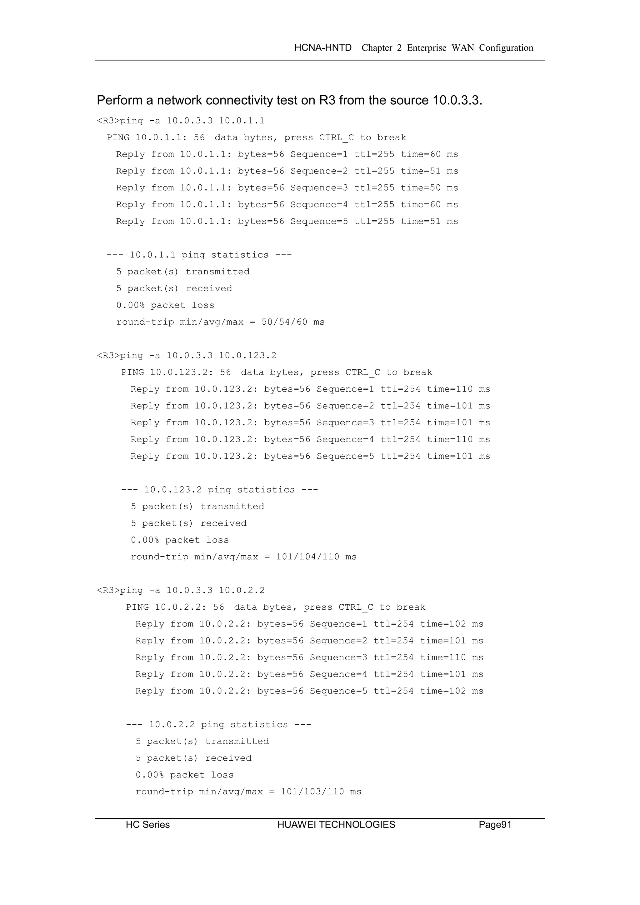
![HCNA-HNTD Chapter 2 Enterprise WAN Configuration
Page92 HUAWEI TECHNOLOGIES HC Series
Final Configuration
[R1]display current-configuration
[V200R003C00SPC200]
#
sysname R1
#
interface Serial2/0/0
link-protocol fr
undo fr inarp
fr map ip 10.0.123.2 102 broadcast
fr map ip 10.0.123.3 103 broadcast
ip address 10.0.123.1 255.255.255.0
ospf network-type p2mp
ospf dr-priority 255
#
interface LoopBack0
ip address 10.0.1.1 255.255.255.0
#
ospf 1 router-id 10.0.1.1
area 0.0.0.0
network 10.0.0.0 0.255.255.255
#
user-interface con 0
authentication-mode password
set authentication password
cipher %$%$dD#}P<HzJ;Xs%X>hOkm!,.+Iq61QK`K6tI}cc-;k_o`C.+L,%$%$
user-interface vty 0 4
#
return
[R2]display current-configuration
[V200R003C00SPC200]
#
sysname R2
#
interface Serial3/0/0
link-protocol fr
undo fr inarp
fr map ip 10.0.123.1 201 broadcast
ip address 10.0.123.2 255.255.255.0
ospf network-type p2mp](https://image.slidesharecdn.com/hcnaintermediatelab-190422104356/75/Hcna-intermediate-lab-100-2048.jpg)
![HCNA-HNTD Chapter 2 Enterprise WAN Configuration
HC Series HUAWEI TECHNOLOGIES Page93
#
interface LoopBack0
ip address 10.0.2.2 255.255.255.0
#
ospf 1 router-id 10.0.2.2
area 0.0.0.0
network 10.0.0.0 0.255.255.255
#
user-interface con 0
authentication-mode password
set authentication password
cipher %$%$|nRPL^hr2IXi7LHDID!/,.*%.8%h;3:,hXO2dk#ikaWI.*(,%$%$
user-interface vty 0 4
#
return
[R3]display current-configuration
[V200R003C00SPC200]
#
sysname R3
#
interface Serial1/0/0
link-protocol fr
undo fr inarp
fr map ip 10.0.123.1 301 broadcast
ip address 10.0.123.3 255.255.255.0
ospf network-type p2mp
#
interface LoopBack0
ip address 10.0.3.3 255.255.255.0
#
ospf 1 router-id 10.0.3.3
area 0.0.0.0
network 10.0.0.0 0.255.255.255
#
user-interface con 0
authentication-mode password
set authentication password
cipher %$%$W|$)M5D}v@bY^gK;>QR,.*d;8Mp>|+EU,:~D~8b59~..*g,%$%$
user-interface vty 0 4
#
return](https://image.slidesharecdn.com/hcnaintermediatelab-190422104356/75/Hcna-intermediate-lab-101-2048.jpg)
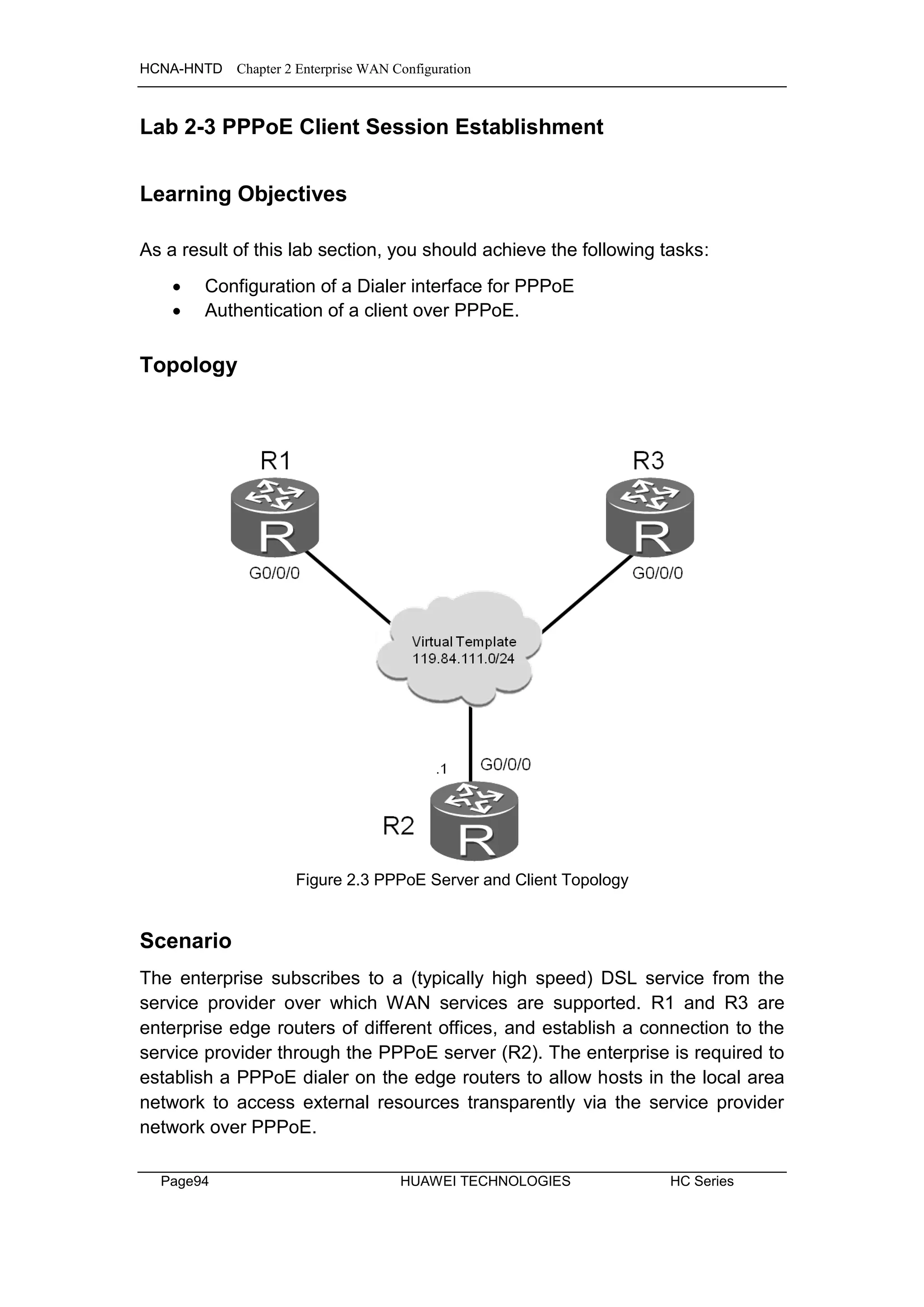
![HCNA-HNTD Chapter 2 Enterprise WAN Configuration
HC Series HUAWEI TECHNOLOGIES Page95
Tasks
Step 1 Preparing the environment.
If you are starting this section with a non-configured device, begin here and
then move to step 3. For those continuing from previous labs, begin at step 2.
<Huawei>system-view
Enter system view, return user view with Ctrl+Z.
[Huawei]sysname R1
<Huawei>system-view
Enter system view, return user view with Ctrl+Z.
[Huawei]sysname R2
<Huawei>system-view
Enter system view, return user view with Ctrl+Z.
[Huawei]sysname R3
Step 2 Clean up the previous configuration
Disable the serial interfaces to avoid routing over the frame relay network.
[R1]interface Serial 2/0/0
[R1-Serial2/0/0]shutdown
[R3]interface Serial 1/0/0
[R3-Serial1/0/0]shutdown
Step 3 Configure PPPoE Server.
The PPPoE server is not part of the enterprise network, however it is required
to allow the enterprise edge routers R1 and R3 to be authenticated.
[R2]ip pool pool1
Info: It's successful to create an IP address pool.
[R2-ip-pool-pool1]network 119.84.111.0 mask 255.255.255.0
[R2-ip-pool-pool1]gateway-list 119.84.111.254
[R2-ip-pool-pool1]quit
[R2]interface Virtual-Template 1
[R2-Virtual-Template1]ppp authentication-mode chap](https://image.slidesharecdn.com/hcnaintermediatelab-190422104356/75/Hcna-intermediate-lab-103-2048.jpg)
![HCNA-HNTD Chapter 2 Enterprise WAN Configuration
Page96 HUAWEI TECHNOLOGIES HC Series
[R2-Virtual-Template1]ip address 119.84.111.254 255.255.255.0
[R2-Virtual-Template1]remote address pool pool1
[R2-Virtual-Template1]quit
Bind the Virtual Template to interface Gigabit Ethernet 0/0/0.
[R2]interface GigabitEthernet 0/0/0
[R2-GigabitEthernet0/0/0]pppoe-server bind virtual-template 1
[R2-GigabitEthernet0/0/0]quit
Configure a PPPoE authenticated user.
[R2]aaa
[R2-aaa]local-user huawei1 password cipher huawei
Info: Add a new user.
[R2-aaa]local-user huawei1 service-type ppp
[R2-aaa]local-user huawei2 password cipher huawei
Info: Add a new user.
[R2-aaa]local-user huawei2 service-type ppp
[R2-aaa]quit
Step 4 Configure PPPoE Client.
Configure R1 as a PPPoE client, for which the dialer interface needs to be
created, and PPP authentication enabled. The PPP authenticated username
and password should match that configured on the PPPoE server.
[R1]dialer-rule
[R1-dialer-rule]dialer-rule 1 ip permit
[R1-dialer-rule]quit
[R1]interface Dialer 1
[R1-Dialer1]dialer user user1
[R1-Dialer1]dialer-group 1
[R1-Dialer1]dialer bundle 1
[R1-Dialer1]ppp chap user huawei1
[R1-Dialer1]ppp chap password cipher huawei
[R1-Dialer1]dialer timer idle 300
[R1-Dialer1]dialer queue-length 8
[R1-Dialer1]ip address ppp-negotiate
[R1-Dialer1]quit](https://image.slidesharecdn.com/hcnaintermediatelab-190422104356/75/Hcna-intermediate-lab-104-2048.jpg)
![HCNA-HNTD Chapter 2 Enterprise WAN Configuration
HC Series HUAWEI TECHNOLOGIES Page97
Bind the PPPoE Dialer to the outbound interface
[R1]interface GigabitEthernet 0/0/0
[R1-GigabitEthernet0/0/0]pppoe-client dial-bundle-number 1
[R1-GigabitEthernet0/0/0]quit
Configure a default static route to the PPPoE server
[R1]ip route-static 0.0.0.0 0.0.0.0 Dialer 1
Configure R3 as a PPPoE client, for which the dialer interface needs to be
created, and PPP authentication enabled. The PPP authenticated username
and password should match that configured on the PPPoE server.
[R3]dialer-rule
[R3-dialer-rule]dialer-rule 1 ip permit
[R3-dialer-rule]quit
[R3]interface Dialer 1
[R3-Dialer1]dialer user user2
[R3-Dialer1]dialer-group 1
[R3-Dialer1]dialer bundle 1
[R3-Dialer1]ppp chap user huawei2
[R3-Dialer1]ppp chap password cipher huawei
[R3-Dialer1]dialer timer idle 300
[R3-Dialer1]dialer queue-length 8
[R3-Dialer1]ip address ppp-negotiate
[R3-Dialer1]quit
Bind the PPPoE Dialer to the outbound interface
[R3]interface GigabitEthernet 0/0/0
[R3-GigabitEthernet0/0/0]pppoe-client dial-bundle-number 1
[R3-GigabitEthernet0/0/0]quit
Configure a default static route to the PPPoE server
[R3]ip route-static 0.0.0.0 0.0.0.0 Dialer 1
Step 5 Verify the configuration results
Execute the command display pppoe-server session all command to view
the status and configuration information.
<R2>display pppoe-server session all
SID Intf State OIntf RemMAC LocMAC
1 Virtual-Template1:0 UP GE0/0/0 00e0.fc03.d0ae 00e0.fc03.7516
2 Virtual-Template1:1 UP GE0/0/0 00e0.fc03.aedd 00e0.fc03.7516
According to displayed information, the session state is normal.](https://image.slidesharecdn.com/hcnaintermediatelab-190422104356/75/Hcna-intermediate-lab-105-2048.jpg)

![HCNA-HNTD Chapter 2 Enterprise WAN Configuration
HC Series HUAWEI TECHNOLOGIES Page99
<R3>display ip interface brief
…output omitted…
Interface IP Address/Mask Physical Protocol
Cellular0/0/0 unassigned down down
Cellular0/0/1 unassigned down down
Dialer1 119.84.111.252/32 up up(s)
GigabitEthernet0/0/0 unassigned up down
…output omitted…
Final Configuration
[R1]display current-configuration
[V200R003C00SPC200]
#
sysname R1
#
aaa
authentication-scheme default
authorization-scheme default
accounting-scheme default
domain default
domain default_admin
local-user admin password cipher %$%$=i~>Xp&aY+*2cEVcS-A23Uwe%$%$
local-user admin service-type http
local-user huawei password cipher %$%$B:%I)Io0H8)[%SB[idM3C/!#%$%$
local-user huawei service-type ppp
#
interface Dialer1
link-protocol ppp
ppp chap user huawei1
ppp chap password cipher %$%$A8E~UjX}@;bhCL*C4w#<%"Ba%$%$
ip address ppp-negotiate
dialer user user1
dialer bundle 1
dialer queue-length 8
dialer timer idle 300
dialer-group 1
#
interface GigabitEthernet0/0/0
pppoe-client dial-bundle-number 1
#
dialer-rule](https://image.slidesharecdn.com/hcnaintermediatelab-190422104356/75/Hcna-intermediate-lab-107-2048.jpg)
![HCNA-HNTD Chapter 2 Enterprise WAN Configuration
Page100 HUAWEI TECHNOLOGIES HC Series
dialer-rule 1 ip permit
#
ip route-static 0.0.0.0 0.0.0.0 Dialer1
#
user-interface con 0
authentication-mode password
set authentication password
cipher %$%$dD#}P<HzJ;Xs%X>hOkm!,.+Iq61QK`K6tI}cc-;k_o`C.+L,%$%$
user-interface vty 0 4
#
return
[R2]dis current-configuration
[V200R003C00SPC200]
#
sysname R2
#
ip pool pool1
gateway-list 119.84.111.254
network 119.84.111.0 mask 255.255.255.0
#
aaa
authentication-scheme default
authorization-scheme default
accounting-scheme default
domain default
domain default_admin
local-user admin password cipher %$%$=i~>Xp&aY+*2cEVcS-A23Uwe%$%$
local-user admin service-type http
local-user huawei1 password cipher %$%$MjCY6,a82N4W`]F]3LMAKG9+%$%$
local-user huawei1 service-type ppp
local-user huawei2 password cipher %$%$Ctq55RX:]R,8Jc13{|,)KH!m%$%$
local-user huawei2 service-type ppp
#
interface Virtual-Template1
ppp authentication-mode chap
remote address pool pool1
ip address 119.84.111.254 255.255.255.0
#
interface GigabitEthernet0/0/0
pppoe-server bind Virtual-Template 1
#](https://image.slidesharecdn.com/hcnaintermediatelab-190422104356/75/Hcna-intermediate-lab-108-2048.jpg)
![HCNA-HNTD Chapter 2 Enterprise WAN Configuration
HC Series HUAWEI TECHNOLOGIES Page101
user-interface con 0
authentication-mode password
set authentication password
cipher %$%$|nRPL^hr2IXi7LHDID!/,.*%.8%h;3:,hXO2dk#ikaWI.*(,%$%$
user-interface vty 0 4
#
return
[R3]display current-configuration
[V200R003C00SPC200]
#
sysname R3
#
aaa
authentication-scheme default
authorization-scheme default
accounting-scheme default
domain default
domain default_admin
local-user admin password cipher %$%$=i~>Xp&aY+*2cEVcS-A23Uwe%$%$
local-user admin service-type http
local-user huawei password cipher %$%$fZsyUk1=O=>:L4'ytgR~D*Im%$%$
local-user huawei service-type ppp
#
interface Dialer1
link-protocol ppp
ppp chap user huawei2
ppp chap password cipher %$%$0f8(;^]1NS:q;SPo8TyP%.Ei%$%$
ip address ppp-negotiate
dialer user user2
dialer bundle 1
dialer queue-length 8
dialer timer idle 300
dialer-group 1
#
interface GigabitEthernet0/0/0
pppoe-client dial-bundle-number 1
#
#
dialer-rule
dialer-rule 1 ip permit
#](https://image.slidesharecdn.com/hcnaintermediatelab-190422104356/75/Hcna-intermediate-lab-109-2048.jpg)
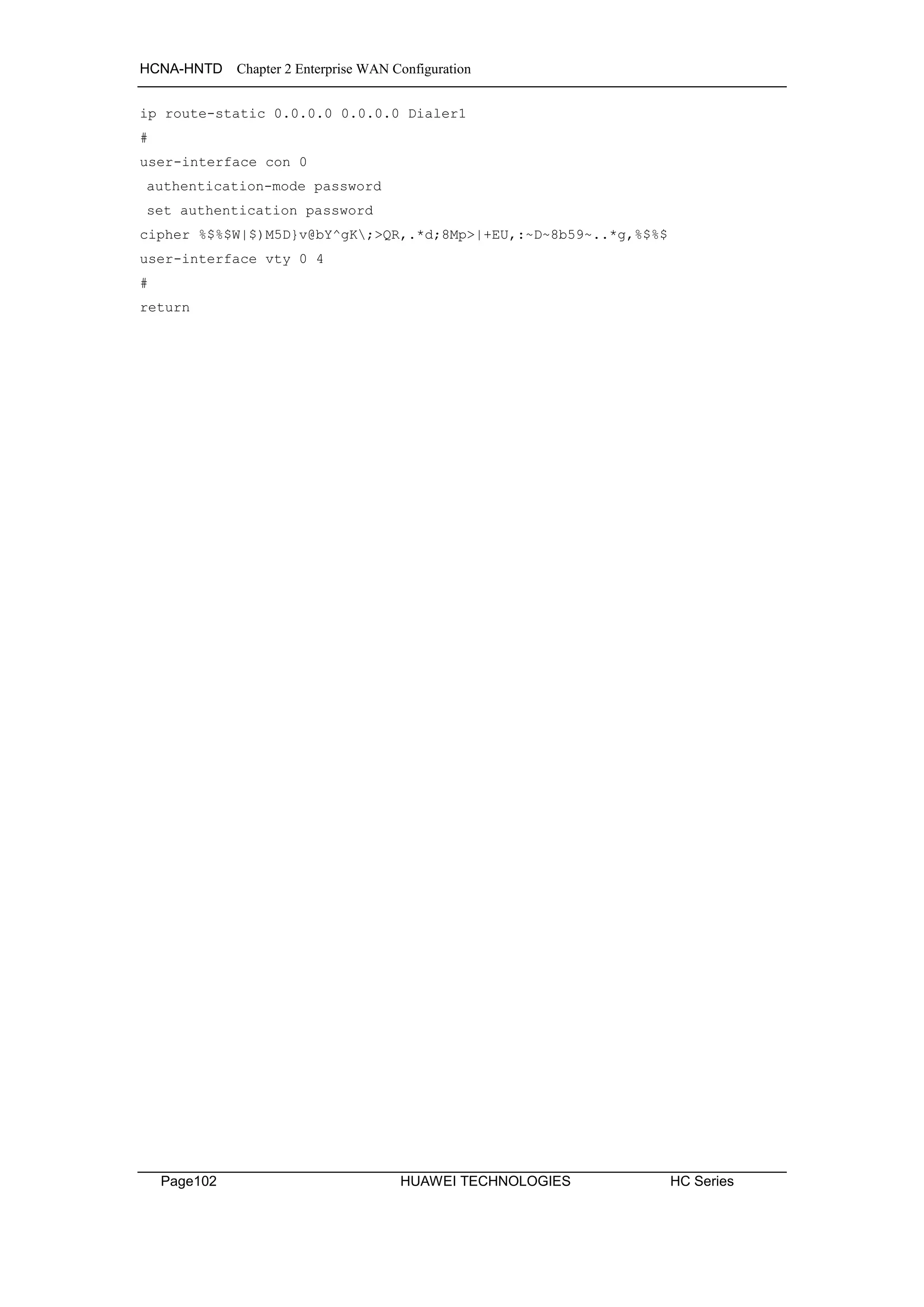

![HCNA-HNTD Chapter 3 Implementing IP Security
Page104 HUAWEI TECHNOLOGIES HC Series
Tasks
Step 1 Preparing the environment
If you are starting this section with a non-configured device, begin here and
then move to step 3. For those continuing from previous labs, begin at step 2.
[Huawei]sysname R1
[Huawei]sysname R2
[Huawei]sysname R3
[Huawei]sysname S1
[S1]vlan 4
[S1-vlan4]quit
[S1]interface vlanif 4
[S1-Vlanif4]ip address 10.0.4.254 24
[Huawei]sysname S2
[S2]vlan 6
[S2-vlan6]quit
[S2]interface vlanif 6
[S2-Vlanif6]ip address 10.0.6.254 24
Step 2 Clean up the previous configuration
Remove the current network being advertised in OSPF, the PPPoE dialer
interfaces, as well as the PPPoE server virtual template configuration from R2.
[R1]ospf
[R1-ospf-1]area 0
[R1-ospf-1-area-0.0.0.0]undo network 10.0.0.0 0.255.255.255
[R1]undo ip route-static 0.0.0.0 0
[R1-GigabitEthernet0/0/0]undo pppoe-client dial-bundle-number 1
[R1]interface Dialer 1
[R1-Dialer1]undo dialer user
[R1]undo interface Dialer 1
[R1]dialer-rule
[R1-dialer-rule]undo dialer-rule 1
[R2]ospf](https://image.slidesharecdn.com/hcnaintermediatelab-190422104356/75/Hcna-intermediate-lab-112-2048.jpg)
![HCNA-HNTD Chapter 3 Implementing IP Security
HC Series HUAWEI TECHNOLOGIES Page105
[R2-ospf-1]area 0
[R2-ospf-1-area-0.0.0.0]undo network 10.0.0.0 0.255.255.255
[R2]interface GigabitEthernet 0/0/0
[R2-GigabitEthernet0/0/0]undo pppoe-server bind
[R2]undo interface Virtual-Template 1
[R2]undo ip pool pool1
[R2]aaa
[R2-aaa]undo local-user huawei1
[R2-aaa]undo local-user huawei2
[R3]ospf
[R3-ospf-1]area 0
[R3-ospf-1-area-0.0.0.0]undo network 10.0.0.0 0.255.255.255
[R3]undo ip route-static 0.0.0.0 0
[R3-GigabitEthernet0/0/0]undo pppoe-client dial-bundle-number 1
[R3]interface Dialer 1
[R3-Dialer1]undo dialer user
[R3]undo interface Dialer 1
[R3]dialer-rule
[R3-dialer-rule]undo dialer-rule 1
Step 3 Configure IP addressing
Configure addressing for the 10.0.13.0/24. 10.0.4.0/24 and 10.0.6.0/24
networks as shown in the topology of figure 7.1.
[R1]interface GigabitEthernet 0/0/0
[R1-GigabitEthernet0/0/0]ip address 10.0.13.1 24
[R2]interface GigabitEthernet 0/0/0
[R2-GigabitEthernet0/0/0]ip address 10.0.13.2 24
[R2-GigabitEthernet0/0/0]interface GigabitEthernet 0/0/1
[R2-GigabitEthernet0/0/1]ip address 10.0.4.2 24
[R2-GigabitEthernet0/0/1]interface GigabitEthernet 0/0/2
[R2-GigabitEthernet0/0/2]ip address 10.0.6.2 24
[R3]interface GigabitEthernet 0/0/0
[R3-GigabitEthernet0/0/0]ip address 10.0.13.3 24
Establish VLAN trunks on S1 and S2. The port link type should already be
configured for interface GigabitEthernet 0/0/2 on S1.](https://image.slidesharecdn.com/hcnaintermediatelab-190422104356/75/Hcna-intermediate-lab-113-2048.jpg)
![HCNA-HNTD Chapter 3 Implementing IP Security
Page106 HUAWEI TECHNOLOGIES HC Series
[S1]interface GigabitEthernet 0/0/2
[S1-GigabitEthernet0/0/2]port link-type trunk
[S1-GigabitEthernet0/0/2]port trunk allow-pass vlan all
[S1-GigabitEthernet0/0/2]port trunk pvid vlan 4
[S1-GigabitEthernet0/0/2]quit
[S2]interface GigabitEthernet 0/0/2
[S2-GigabitEthernet0/0/2]port link-type trunk
[S2-GigabitEthernet0/0/2]port trunk allow-pass vlan all
[S2-GigabitEthernet0/0/2]port trunk pvid vlan 6
[S2-GigabitEthernet0/0/2]quit
Step 4 Configure OSPF to enable internetwork communication
Configure OSPF for R1, R2, and R3. Ensure that all are part of the same
OSPF area and advertise the networks that have been created.
[R1]ospf
[R1-ospf-1]area 0
[R1-ospf-1-area-0.0.0.0]network 10.0.13.0 0.0.0.255
[R2]ospf
[R2-ospf-1]area 0
[R2-ospf-1-area-0.0.0.0]network 10.0.13.0 0.0.0.255
[R2-ospf-1-area-0.0.0.0]network 10.0.4.0 0.0.0.255
[R2-ospf-1-area-0.0.0.0]network 10.0.6.0 0.0.0.255
[R3]ospf
[R3-ospf-1]area 0
[R3-ospf-1-area-0.0.0.0]network 10.0.13.0 0.0.0.255
Configure a static route on S1 and S2, the nexthop as the private network’s
gateway.
[S1]ip route-static 0.0.0.0 0.0.0.0 10.0.4.2
[S2]ip route-static 0.0.0.0 0.0.0.0 10.0.6.2
Verify that a path exists from R1 and R3 to S1 and S2.](https://image.slidesharecdn.com/hcnaintermediatelab-190422104356/75/Hcna-intermediate-lab-114-2048.jpg)

![HCNA-HNTD Chapter 3 Implementing IP Security
Page108 HUAWEI TECHNOLOGIES HC Series
<R3>ping 10.0.6.254
PING 10.0.6.254: 56 data bytes, press CTRL_C to break
Reply from 10.0.6.254: bytes=56 Sequence=1 ttl=253 time=10 ms
Reply from 10.0.6.254: bytes=56 Sequence=2 ttl=253 time=2 ms
Reply from 10.0.6.254: bytes=56 Sequence=3 ttl=253 time=2 ms
Reply from 10.0.6.254: bytes=56 Sequence=4 ttl=253 time=10 ms
Reply from 10.0.6.254: bytes=56 Sequence=5 ttl=253 time=2 ms
--- 10.0.6.254 ping statistics ---
5 packet(s) transmitted
5 packet(s) received
0.00% packet loss
round-trip min/avg/max = 2/5/10 ms
Step 5 Configure Filters using Access Control Lists
Configure S1 as a telnet server.
[S1]user-interface vty 0 4
[S1-ui-vty0-4]authentication-mode password
[S1-ui-vty0-4]set authentication password cipher huawei
Configure S2 as an FTP server.
[S2]ftp server enable
[S2]aaa
[S2-aaa]local-user huawei password cipher huawei
[S2-aaa]local-user huawei service-type ftp
[S2-aaa]local-user huawei ftp-directory flash:
Configure an access control list on R2 to allow R1 to access the telnet server,
and R3 to access the FTP server.
[R2]acl 3000
[R2-acl-adv-3000]rule 5 permit tcp source 10.0.13.1 0.0.0.0 destination
10.0.4.254 0.0.0.0 destination-port eq 23
[R2-acl-adv-3000]rule 10 permit tcp source 10.0.13.3 0.0.0.0 destination
10.0.6.254 0.0.0.0 destination-port range 20 21
[R2-acl-adv-3000]rule 15 deny ip source any
[R2-acl-adv-3000]quit
Apply the ACL to the Gigabit Ethernet 0/0/0 interface of R2.
[R2]interface GigabitEthernet0/0/0
[R2-GigabitEthernet0/0/0]traffic-filter inbound acl 3000](https://image.slidesharecdn.com/hcnaintermediatelab-190422104356/75/Hcna-intermediate-lab-116-2048.jpg)
![HCNA-HNTD Chapter 3 Implementing IP Security
HC Series HUAWEI TECHNOLOGIES Page109
Verify the results of the access control list on the network.
<R1>telnet 10.0.4.254
Press CTRL_] to quit telnet mode
Trying 10.0.4.254 ...
Connected to 10.0.4.254 ...
Login authentication
Password:
Info: The max number of VTY users is 5, and the number
of current VTY users on line is 1.
<S1>
Note: use the quit command to exit the telnet session
<R1>ftp 10.0.6.254
Trying 10.0.6.254 ...
Press CTRL+K to abort
Error: Failed to connect to the remote host.
Note: The FTP connection may take a while to respond (approx 60 seconds).
<R3>telnet 10.0.4.254
Press CTRL_] to quit telnet mode
Trying 10.0.4.254 ...
Error: Can't connect to the remote host
<R3>ftp 10.0.6.254
Trying 10.0.6.254 ...
Press CTRL+K to abort
Connected to 10.0.6.254.
220 FTP service ready.
User(10.0.6.254:(none)):huawei
331 Password required for huawei.
Enter password:
230 User logged in.
[R3-ftp]
Note: The bye command can be used to close the FTP connection](https://image.slidesharecdn.com/hcnaintermediatelab-190422104356/75/Hcna-intermediate-lab-117-2048.jpg)
![HCNA-HNTD Chapter 3 Implementing IP Security
Page110 HUAWEI TECHNOLOGIES HC Series
Additional Exercises: Analyzing and Verifying
FTP requires two ports to be defined in the access control list, why is this?
Should basic ACL and advanced ACL be deployed near the source network or
target network, and why?
Final Configuration
<R1>display current-configuration
[V200R003C00SPC200]
#
sysname R1
#
aaa
authentication-scheme default
authorization-scheme default
accounting-scheme default
domain default
domain default_admin
local-user admin password cipher %$%$=i~>Xp&aY+*2cEVcS-A23Uwe%$%$
local-user admin service-type http
local-user huawei password cipher %$%$B:%I)Io0H8)[%SB[idM3C/!#%$%$
local-user huawei service-type ppp
#
interface GigabitEthernet0/0/0
ip address 10.0.13.1 255.255.255.0
#
ospf 1 router-id 10.0.1.1
area 0.0.0.0
network 10.0.13.0 0.0.0.255
#
user-interface con 0
authentication-mode password
set authentication password
cipher %$%$dD#}P<HzJ;Xs%X>hOkm!,.+Iq61QK`K6tI}cc-;k_o`C.+L,%$%$
user-interface vty 0 4
#
return](https://image.slidesharecdn.com/hcnaintermediatelab-190422104356/75/Hcna-intermediate-lab-118-2048.jpg)
![HCNA-HNTD Chapter 3 Implementing IP Security
HC Series HUAWEI TECHNOLOGIES Page111
<R2>display current-configuration
[V200R003C00SPC200]
#
sysname R2
#
acl number 3000
rule 5 permit tcp source 10.0.13.1 0 destination 10.0.4.254 0 destination-port
eq telnet
rule 10 permit tcp source 10.0.13.3 0 destination 10.0.6.254 0 destination-port
range ftp-data ftp
rule 15 deny ip
#
interface GigabitEthernet0/0/0
ip address 10.0.13.2 255.255.255.0
traffic-filter inbound acl 3000
#
interface GigabitEthernet0/0/1
ip address 10.0.4.2 255.255.255.0
#
interface GigabitEthernet0/0/2
ip address 10.0.6.2 255.255.255.0
#
ospf 1 router-id 10.0.2.2
area 0.0.0.0
network 10.0.4.0 0.0.0.255
network 10.0.6.0 0.0.0.255
network 10.0.13.0 0.0.0.255
#
user-interface con 0
authentication-mode password
set authentication password
cipher %$%$|nRPL^hr2IXi7LHDID!/,.*%.8%h;3:,hXO2dk#ikaWI.*(,%$%$
user-interface vty 0 4
#
return
<R3>display current-configuration
[V200R003C00SPC200]
#
sysname R3
#
interface GigabitEthernet0/0/0](https://image.slidesharecdn.com/hcnaintermediatelab-190422104356/75/Hcna-intermediate-lab-119-2048.jpg)
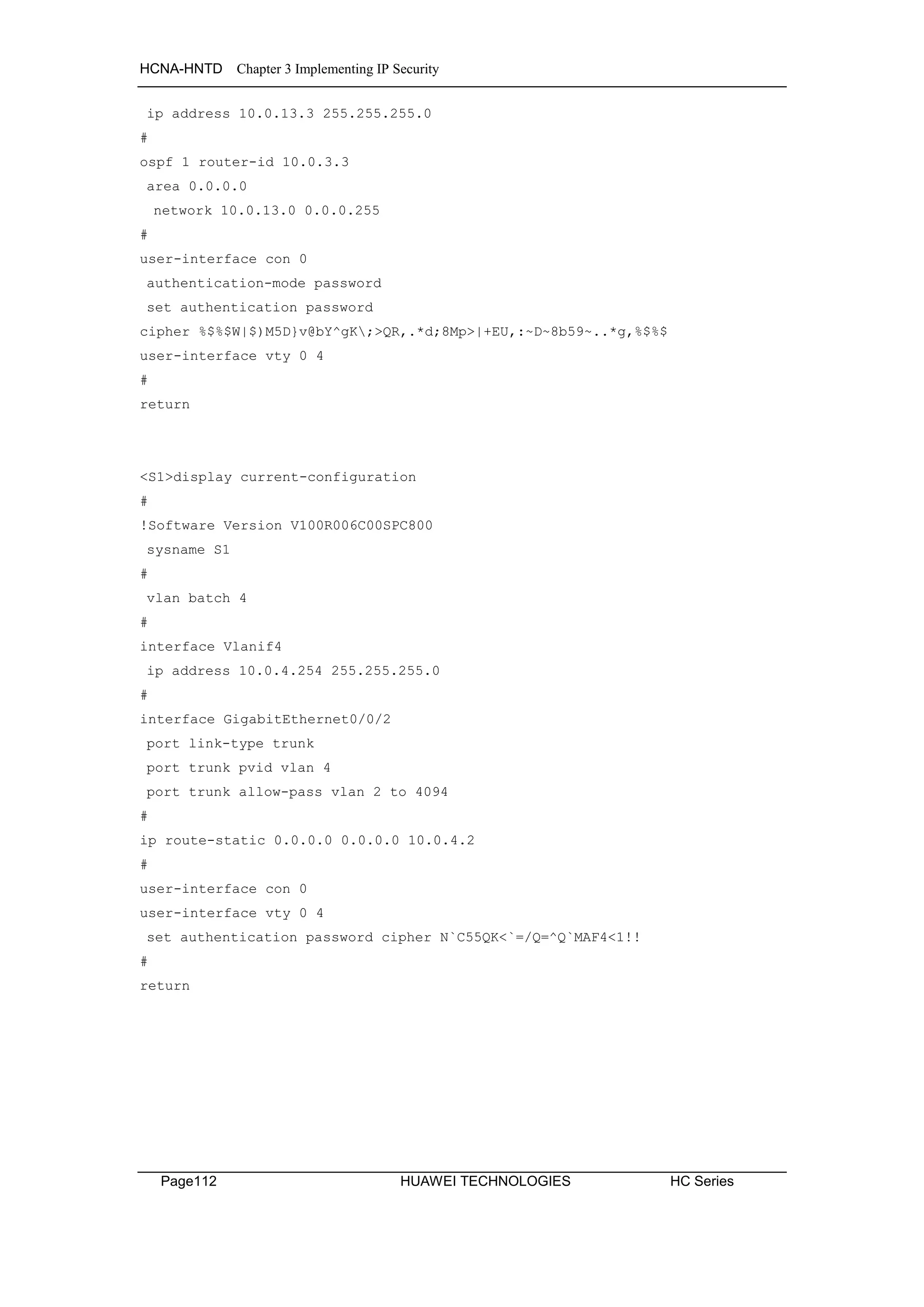


![HCNA-HNTD Chapter 3 Implementing IP Security
HC Series HUAWEI TECHNOLOGIES Page115
Tasks
Step 1 Preparing the environment
If you are starting this section with a non-configured device, begin here and
then move to step 3. For those continuing from previous labs, begin at step 2.
[Huawei]sysname R1
[R1]inter GigabitEthernet0/0/1
[R1-GigabitEthernet0/0/1]ip address 10.0.4.1 24
[Huawei]sysname R3
[R3]interface GigabitEthernet0/0/2
[R3-GigabitEthernet0/0/2]ip address 10.0.6.3 24
[Huawei]sysname S1
[S1]vlan 4
[S1-vlan3]quit
[S1]interface vlanif 4
[S1-Vlanif4]ip address 10.0.4.254 24
[S1-Vlanif4]quit
[Huawei]sysname S2
[S2]vlan 6
[S2-vlan6]quit
[S2]interface vlanif 6
[S2-Vlanif6]ip address 10.0.6.254 24
[S2-Vlanif6]quit
Step 2 Clean up the previous configuration
Re-establish the connection to S1 and S2 via Gigabit Ethernet 0/0/1 on R1 and
Gigabit Ethernet 0/0/2 on R3. Remove OSPF from all routers.
[R1]interface GigabitEthernet 0/0/0
[R1-GigabitEthernet0/0/0]undo ip address
[R1]interface GigabitEthernet 0/0/1
[R1-GigabitEthernet0/0/1]undo shutdown
[R1]undo ospf 1
Warning: The OSPF process will be deleted. Continue? [Y/N]:y](https://image.slidesharecdn.com/hcnaintermediatelab-190422104356/75/Hcna-intermediate-lab-123-2048.jpg)
![HCNA-HNTD Chapter 3 Implementing IP Security
Page116 HUAWEI TECHNOLOGIES HC Series
[R2]undo ospf 1
Warning: The OSPF process will be deleted. Continue? [Y/N]:y
[R3-GigabitEthernet0/0/0]undo ip address
[R3]interface GigabitEthernet 0/0/2
[R3-GigabitEthernet0/0/2]undo shutdown
[R3]undo ospf 1
Warning: The OSPF process will be deleted. Continue? [Y/N]:y
Remove the static routes pointing to R2 on S1 and S2.
[S1]undo ip route-static 0.0.0.0 0.0.0.0
[S2]undo ip route-static 0.0.0.0 0.0.0.0
Step 3 Implement VLAN configuration for S1 and S2
[S1]interface GigabitEthernet 0/0/1
[S1-GigabitEthernet0/0/1]port link-type trunk
[S1-GigabitEthernet0/0/1]port trunk pvid vlan 4
[S1-GigabitEthernet0/0/1]port trunk allow-pass vlan all
[S1-GigabitEthernet0/0/1]quit
[S2]interface GigabitEthernet 0/0/3
[S2-GigabitEthernet0/0/3]port link-type trunk
[S2-GigabitEthernet0/0/3]port trunk pvid vlan 6
[S2-GigabitEthernet0/0/3]port trunk allow-pass vlan all
[R1]interface GigabitEthernet0/0/0
[R1-GigabitEthernet0/0/0]ip address 119.84.111.1 24
[R3]interface GigabitEthernet0/0/0
[R3-GigabitEthernet0/0/0]ip address 119.84.111.3 24](https://image.slidesharecdn.com/hcnaintermediatelab-190422104356/75/Hcna-intermediate-lab-124-2048.jpg)
![HCNA-HNTD Chapter 3 Implementing IP Security
HC Series HUAWEI TECHNOLOGIES Page117
Verify that R1 is able to reach both S1 and R3.
<R1>ping 10.0.4.254
PING 10.0.4.254: 56 data bytes, press CTRL_C to break
Reply from 10.0.4.254: bytes=56 Sequence=1 ttl=255 time=23 ms
Reply from 10.0.4.254: bytes=56 Sequence=2 ttl=254 time=1 ms
Reply from 10.0.4.254: bytes=56 Sequence=3 ttl=254 time=1 ms
Reply from 10.0.4.254: bytes=56 Sequence=4 ttl=254 time=10 ms
Reply from 10.0.4.254: bytes=56 Sequence=5 ttl=254 time=1 ms
--- 10.0.4.254 ping statistics ---
5 packet(s) transmitted
5 packet(s) received
0.00% packet loss
round-trip min/avg/max = 1/7/23 ms
<R1>ping 119.84.111.3
PING 119.84.111.3: 56 data bytes, press CTRL_C to break
Reply from 119.84.111.3: bytes=56 Sequence=1 ttl=255 time=1 ms
Reply from 119.84.111.3: bytes=56 Sequence=2 ttl=255 time=10 ms
Reply from 119.84.111.3: bytes=56 Sequence=3 ttl=255 time=1 ms
Reply from 119.84.111.3: bytes=56 Sequence=4 ttl=255 time=1 ms
Reply from 119.84.111.3: bytes=56 Sequence=5 ttl=255 time=10 ms
--- 119.84.111.3 ping statistics ---
5 packet(s) transmitted
5 packet(s) received
0.00% packet loss
round-trip min/avg/max = 1/4/10 ms
Step 4 Configure Access Control Lists for R1 and R3
Configure an advanced ACL on R1 and select the data flow with the source of
S1, the destination of R3, and destined for the telnet service port.
[R1]acl 3000
[R1-acl-adv-3000]rule 5 permit tcp source 10.0.4.254 0.0.0.0 destination
119.84.111.3 0.0.0.0 destination-port eq 23
[R1-acl-adv-3000]rule 10 permit ip source 10.0.4.0 0.0.0.255 destination any
[R1-acl-adv-3000]rule 15 deny ip
Configure a basic ACL on R3 and select the data flow whose source IP
address is 10.0.6.0/24.
[R3]acl 2000
[R3-acl-basic-2000]rule permit source 10.0.6.0 0.0.0.255](https://image.slidesharecdn.com/hcnaintermediatelab-190422104356/75/Hcna-intermediate-lab-125-2048.jpg)
![HCNA-HNTD Chapter 3 Implementing IP Security
Page118 HUAWEI TECHNOLOGIES HC Series
Step 5 Configure Dynamic NAT
Configure static route on S1 and S2,the nexthop as the private network’s
gateway.
[S1]ip route-static 0.0.0.0 0.0.0.0 10.0.4.1
[S2]ip route-static 0.0.0.0 0.0.0.0 10.0.6.3
Configure dynamic NAT on the GigabitEthernet0/0/0 interface of R1.
[R1]nat address-group 1 119.84.111.240 119.84.111.243
[R1]interface GigabitEthernet 0/0/0
[R1-GigabitEthernet0/0/0]nat outbound 3000 address-group 1
Configure R3 as the telnet server.
[R3]user-interface vty 0 4
[R3-ui-vty0-4]authentication-mode password
[R3-ui-vty0-4]set authentication password cipher huawei
[R3-ui-vty0-4]quit
Verify the address group has been configured correctly
<R1>display nat address-group
NAT Address-Group Information:
--------------------------------------
Index Start-address End-address
--------------------------------------
1 119.84.111.240 119.84.111.243
--------------------------------------
Total : 1
Test connectivity to the gateway of the remote peer from the internal network.
<S1>ping 119.84.111.3
PING 119.84.111.3: 56 data bytes, press CTRL_C to break
Request time out
Reply from 119.84.111.3: bytes=56 Sequence=2 ttl=254 time=1 ms
Reply from 119.84.111.3: bytes=56 Sequence=3 ttl=254 time=1 ms
Reply from 119.84.111.3: bytes=56 Sequence=4 ttl=254 time=1 ms
Reply from 119.84.111.3: bytes=56 Sequence=5 ttl=254 time=1 ms
--- 119.84.111.3 ping statistics ---
5 packet(s) transmitted
4 packet(s) received
20.00% packet loss
round-trip min/avg/max = 1/1/1 ms](https://image.slidesharecdn.com/hcnaintermediatelab-190422104356/75/Hcna-intermediate-lab-126-2048.jpg)

![HCNA-HNTD Chapter 3 Implementing IP Security
Page120 HUAWEI TECHNOLOGIES HC Series
The ICMP session has a lifetime of only 20 seconds and therefore may not
appear to be present when displaying the NAT session results. The following
command can be used in this case to extend the period over which the ICMP
results are maintained:
[R1]firewall-nat session icmp aging-time 300
Configure easyIP on the Gigabit Ethernet 0/0/0 interface of R3, associating the
easyIP configuration with ACL 2000 that had been configured earlier.
[R3-GigabitEthernet0/0/0]nat outbound 2000
Test the connectivity from S2 to R1 via R3.
<S2>ping 119.84.111.1
PING 119.84.111.1: 56 data bytes, press CTRL_C to break
Reply from 119.84.111.1: bytes=56 Sequence=1 ttl=254 time=1 ms
Reply from 119.84.111.1: bytes=56 Sequence=2 ttl=254 time=1 ms
Reply from 119.84.111.1: bytes=56 Sequence=3 ttl=254 time=1 ms
Reply from 119.84.111.1: bytes=56 Sequence=4 ttl=254 time=1 ms
Reply from 119.84.111.1: bytes=56 Sequence=5 ttl=254 time=1 ms
--- 119.84.111.1 ping statistics ---
5 packet(s) transmitted
5 packet(s) received
0.00% packet loss
round-trip min/avg/max = 1/1/1 ms
<R3>display acl 2000
Basic ACL 2000, 1 rule
Acl's step is 5
rule 5 permit source 10.0.6.0 0.0.0.255 (1 matches)
<R3>display nat outbound acl 2000
NAT Outbound Information:
---------------------------------------------------------------------
Interface Acl Address-group/IP/Interface Type
---------------------------------------------------------------------
GigabitEthernet0/0/0 2000 119.84.111.3 easyip
---------------------------------------------------------------------
Total : 1](https://image.slidesharecdn.com/hcnaintermediatelab-190422104356/75/Hcna-intermediate-lab-128-2048.jpg)
![HCNA-HNTD Chapter 3 Implementing IP Security
HC Series HUAWEI TECHNOLOGIES Page121
Final Configuration
<R1>display current-configuration
[V200R003C00SPC200]
#
sysname R1
#
firewall-nat session icmp aging-time 300
#
acl number 3000
rule 5 permit tcp source 10.0.4.254 0 destination 119.84.111.3 0 destination-port
eq telnet
rule 10 permit ip source 10.0.4.0 0.0.0.255
rule 15 deny ip
#
nat address-group 1 119.84.111.240 119.84.111.243
#
interface GigabitEthernet0/0/0
ip address 119.84.111.1 255.255.255.0
nat outbound 3000 address-group 1
#
interface GigabitEthernet0/0/1
ip address 10.0.4.1 255.255.255.0
#
user-interface con 0
authentication-mode password
set authentication password
cipher %$%$dD#}P<HzJ;Xs%X>hOkm!,.+Iq61QK`K6tI}cc-;k_o`C.+L,%$%$
user-interface vty 0 4
#
return
<R3>display current-configuration
[V200R003C00SPC200]
#
sysname R3
#
acl number 2000
rule 5 permit source 10.0.6.0 0.0.0.255
#
interface GigabitEthernet0/0/0](https://image.slidesharecdn.com/hcnaintermediatelab-190422104356/75/Hcna-intermediate-lab-129-2048.jpg)


![HCNA-HNTD Chapter 3 Implementing IP Security
HC Series HUAWEI TECHNOLOGIES Page125
Tasks
Step 1 Preparing the environment
If you are starting this section with a non-configured device, begin here and
then move to step 3. For those continuing from previous labs, begin at step 2.
[Huawei]sysname R1
[R1]interface GigabitEthernet0/0/0
[R1-GigabitEthernet0/0/0]ip address 119.84.111.1 24
[Huawei]sysname R3
[R3]inter GigabitEthernet0/0/0
[R3-GigabitEthernet0/0/0]ip address 119.84.111.3 24
Step 2 Clean up the previous configuration
Remove the previous NAT and ACL configuration from R1 and R3.
[R1]interface GigabitEthernet 0/0/0
[R1-GigabitEthernet0/0/0]undo nat outbound 3000 address-group 1
[R1-GigabitEthernet0/0/0]quit
[R1]undo nat address-group 1
[R1]undo acl 3000
[R3]interface GigabitEthernet 0/0/0
[R3-GigabitEthernet0/0/0]undo nat outbound 2000
[R3-GigabitEthernet0/0/0]quit
[R3]undo acl 2000
Step 3 Verify connectivity between R1 and R3
<R1>ping 119.84.111.3
PING 119.84.111.3: 56 data bytes, press CTRL_C to break
Reply from 119.84.111.3: bytes=56 Sequence=1 ttl=255 time=70 ms
Reply from 119.84.111.3: bytes=56 Sequence=2 ttl=255 time=20 ms
Reply from 119.84.111.3: bytes=56 Sequence=3 ttl=255 time=10 ms
Reply from 119.84.111.3: bytes=56 Sequence=4 ttl=255 time=20 ms
Reply from 119.84.111.3: bytes=56 Sequence=5 ttl=255 time=10 ms](https://image.slidesharecdn.com/hcnaintermediatelab-190422104356/75/Hcna-intermediate-lab-133-2048.jpg)
![HCNA-HNTD Chapter 3 Implementing IP Security
Page126 HUAWEI TECHNOLOGIES HC Series
--- 119.84.111.3 ping statistics ---
5 packet(s) transmitted
5 packet(s) received
0.00% packet loss
round-trip min/avg/max = 10/26/70 ms
Step 4 Perform AAA configuration on R1
Configure an authentication-scheme and authorization-scheme on R1. The
configuration for R3 can be found at step 5.
[R1]aaa
[R1-aaa]authentication-scheme auth1
Info: Create a new authentication scheme.
[R1-aaa-authen-auth1]authentication-mode local
[R1-aaa-authen-auth1]quit
[R1-aaa]authorization-scheme auth2
Info: Create a new authorization scheme.
[R1-aaa-author-auth2]authorization-mode local
[R1-aaa-author-auth2]quit
Configure the domain huawei on R1, then create a user and apply the user to
this domain.
[R1-aaa]domain huawei
[R1-aaa-domain-huawei]authentication-scheme auth1
[R1-aaa-domain-huawei]authorization-scheme auth2
[R1-aaa-domain-huawei]quit
[R1-aaa]local-user user1@huawei password cipher huawei
[R1-aaa]local-user user1@huawei service-type telnet
[R1-aaa]local-user user1@huawei privilege level 0
Configure R1 as the telnet server, using AAA authentication mode.
[R1]user-interface vty 0 4
[R1-ui-vty0-4]authentication-mode aaa](https://image.slidesharecdn.com/hcnaintermediatelab-190422104356/75/Hcna-intermediate-lab-134-2048.jpg)
![HCNA-HNTD Chapter 3 Implementing IP Security
HC Series HUAWEI TECHNOLOGIES Page127
Verify whether the telnet service on R1 has been established successfully.
<R3>telnet 119.84.111.1
Press CTRL_] to quit telnet mode
Trying 119.84.111.1 ...
Connected to 119.84.111.1 ...
Login authentication
Username:user1@huawei
Password:
<R1>system-view
^
Error: Unrecognized command found at '^' position.
<R1>quit
Operations are restricted as user privileges are limited to privilege level 0 for
user1@huawei.
Step 5 Perform AAA configuration on R3
[R3]aaa
[R3-aaa]authentication-scheme auth1
Info: Create a new authentication scheme.
[R3-aaa-authen-auth1]authentication-mode local
[R3-aaa-authen-auth1]quit
[R3-aaa]authorization-scheme auth2
Info: Create a new authorization scheme.
[R3-aaa-author-auth2]authorization-mode local
[R3-aaa-author-auth2]quit
Configure the domain huawei on R3, then create a user and apply the user to
this domain.
[R3-aaa]domain huawei
[R3-aaa-domain-huawei]authentication-scheme auth1
[R3-aaa-domain-huawei]authorization-scheme auth2
[R3-aaa-domain-huawei]quit
[R3-aaa]local-user user3@huawei password cipher huawei
[R3-aaa]local-user user3@huawei service-type telnet
[R3-aaa]local-user user3@huawei privilege level 0](https://image.slidesharecdn.com/hcnaintermediatelab-190422104356/75/Hcna-intermediate-lab-135-2048.jpg)
![HCNA-HNTD Chapter 3 Implementing IP Security
Page128 HUAWEI TECHNOLOGIES HC Series
Configure the telnet service on R3 to use AAA authentication mode.
[R3]user-interface vty 0 4
[R3-ui-vty0-4]authentication-mode aaa
Verify the results of implementing AAA on the vty interface.
.
<R1>telnet 119.84.111.3
Press CTRL_] to quit telnet mode
Trying 119.84.111.1 ...
Connected to 119.84.111.1 ...
Login authentication
Username:user3@huawei
Password:
<R3>system-view
^
Error: Unrecognized command found at '^' position.
<R3>
Operations are restricted as user privileges are set to privilege level 0 for
user3@huawei.
Step 6 Observe the results of the AAA configuration
<R1>display domain name huawei
Domain-name : huawei
Domain-state : Active
Authentication-scheme-name : auth1
Accounting-scheme-name : default
Authorization-scheme-name : auth2
Service-scheme-name : -
RADIUS-server-template : -
HWTACACS-server-template : -
User-group : -](https://image.slidesharecdn.com/hcnaintermediatelab-190422104356/75/Hcna-intermediate-lab-136-2048.jpg)
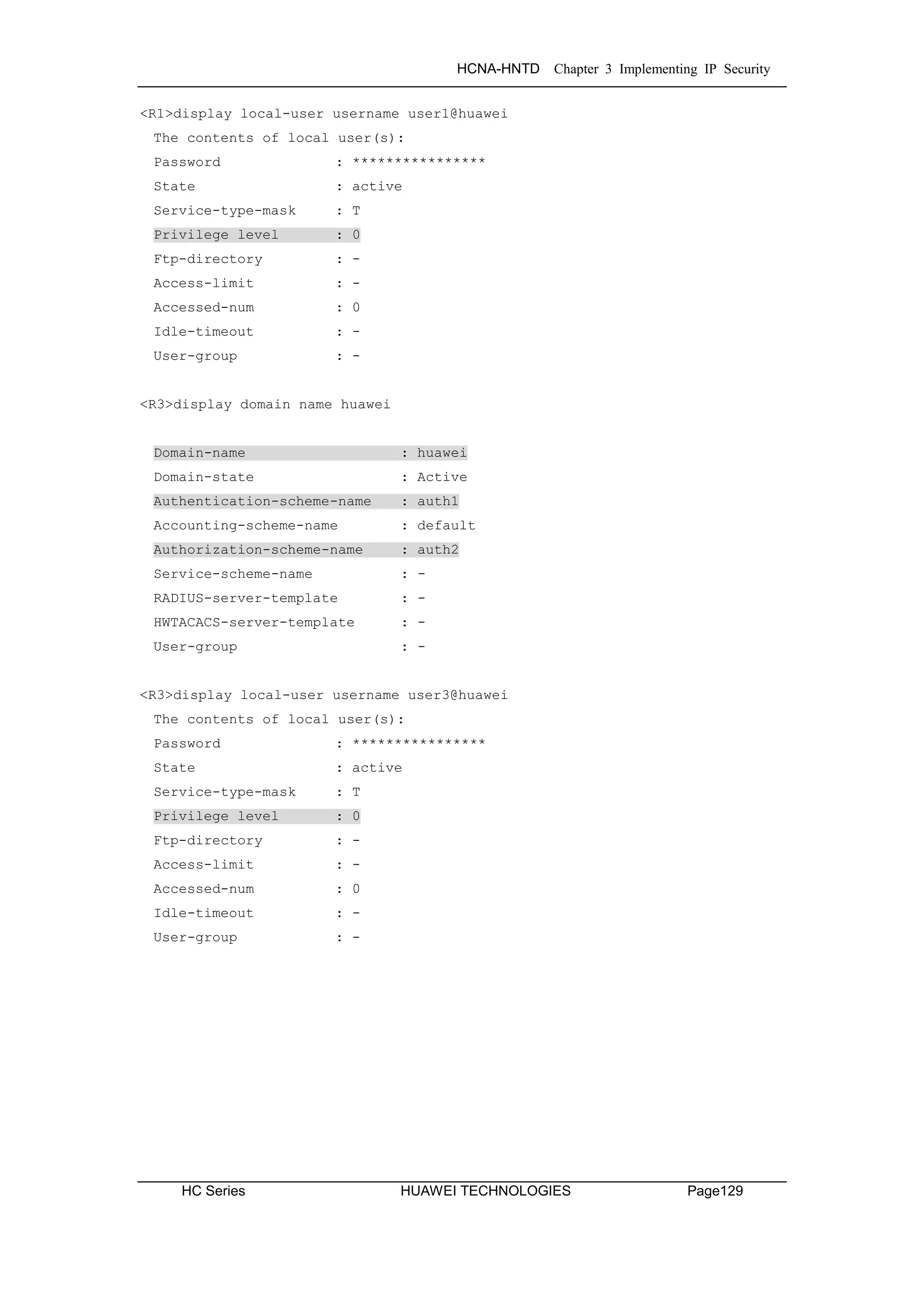
![HCNA-HNTD Chapter 3 Implementing IP Security
Page130 HUAWEI TECHNOLOGIES HC Series
Final Configuration
<R1>display current-configuration
[V200R003C00SPC200]
#
sysname R1
#
aaa
authentication-scheme default
authentication-scheme auth1
authorization-scheme default
authorization-scheme auth2
accounting-scheme default
domain default
domain default_admin
domain huawei
authentication-scheme auth1
authorization-scheme auth2
local-user admin password cipher %$%$=i~>Xp&aY+*2cEVcS-A23Uwe%$%$
local-user admin service-type http
local-user huawei password cipher %$%$B:%I)Io0H8)[%SB[idM3C/!#%$%$
local-user huawei service-type ppp
local-user user1@huawei password cipher %$%$^L*5IP'0^A!;R)R*L=LFcXgv%$%$
local-user user1@huawei privilege level 0
local-user user1@huawei service-type telnet
#
interface GigabitEthernet0/0/0
ip address 119.84.111.1 255.255.255.0
nat outbound 3000 address-group 1 //may remain from previous labs
#
user-interface con 0
authentication-mode password
set authentication password
cipher %$%$dD#}P<HzJ;Xs%X>hOkm!,.+Iq61QK`K6tI}cc-;k_o`C.+L,%$%$
user-interface vty 0 4
authentication-mode aaa
#
return](https://image.slidesharecdn.com/hcnaintermediatelab-190422104356/75/Hcna-intermediate-lab-138-2048.jpg)
![HCNA-HNTD Chapter 3 Implementing IP Security
HC Series HUAWEI TECHNOLOGIES Page131
<R3>dis current-configuration
[V200R003C00SPC200]
#
sysname R3
#
aaa
authentication-scheme default
authentication-scheme auth1
authorization-scheme default
authorization-scheme auth2
accounting-scheme default
domain default
domain default_admin
domain huawei
authentication-scheme auth1
authorization-scheme auth2
local-user admin password cipher %$%$=i~>Xp&aY+*2cEVcS-A23Uwe%$%$
local-user admin service-type http
local-user huawei password cipher %$%$fZsyUk1=O=>:L4'ytgR~D*Im%$%$
local-user huawei service-type ppp
local-user user3@huawei password cipher %$%$WQt.;bEsR<8fz3LCiPY,che_%$%$
local-user user3@huawei privilege level 0
local-user user3@huawei service-type telnet
#
interface GigabitEthernet0/0/0
ip address 119.84.111.3 255.255.255.0
nat outbound 2000 //may remain from previous labs
#
user-interface con 0
authentication-mode password
set authentication password
cipher %$%$W|$)M5D}v@bY^gK;>QR,.*d;8Mp>|+EU,:~D~8b59~..*g,%$%$
user-interface vty 0 4
authentication-mode aaa
#
return](https://image.slidesharecdn.com/hcnaintermediatelab-190422104356/75/Hcna-intermediate-lab-139-2048.jpg)

![HCNA-HNTD Chapter 3 Implementing IP Security
HC Series HUAWEI TECHNOLOGIES Page133
Tasks
Step 1 Preparing the environment.
If you are starting this section with a non-configured device, begin here and
then move to step 3. For those continuing from previous labs, begin at step 2.
<Huawei>system-view
[Huawei]sysname R1
[R1]interface Serial 1/0/0
[R1-Serial1/0/0]ip address 10.0.12.1 24
[R1-Serial1/0/0]interface loopback 0
[R1-LoopBack0]ip address 10.0.1.1 24
<Huawei>system-view
[Huawei]sysname R2
[R2]interface Serial 1/0/0
[R2-Serial1/0/0]ip address 10.0.12.2 24
[R2-Serial1/0/0]interface serial 2/0/0
[R2-Serial2/0/0]ip address 10.0.23.2 24
[R2-Serial2/0/0]interface loopback 0
[R2-LoopBack0]ip address 10.0.2.2 24
<Huawei>system-view
[Huawei]sysname R3
[R3]interface Serial 2/0/0
[R3-Serial2/0/0]ip address 10.0.23.3 24
[R3-Serial2/0/0]interface loopback 0
[R3-LoopBack0]ip address 10.0.3.3 24
Step 2 Clean up the previous configuration.
Remove the addressing for the Gigabit Ethernet 0/0/0 interface on R1 & R3,
and disable the interfaces as shown to prevent alternative routes.
[R1]interface GigabitEthernet 0/0/0
[R1-GigabitEthernet0/0/0]undo ip address
[R1-GigabitEthernet0/0/0]quit
[R1]interface GigabitEthernet 0/0/1
[R1-GigabitEthernet0/0/1]shutdown
[R1-GigabitEthernet0/0/1]quit
[R1]interface Serial 1/0/0
[R1-Serial1/0/0]undo shutdown](https://image.slidesharecdn.com/hcnaintermediatelab-190422104356/75/Hcna-intermediate-lab-141-2048.jpg)
![HCNA-HNTD Chapter 3 Implementing IP Security
Page134 HUAWEI TECHNOLOGIES HC Series
[R2]interface Serial 1/0/0
[R2-Serial1/0/0]undo shutdown
[R2]interface Serial 2/0/0
[R2-Serial2/0/0]undo shutdown
[R3]interface GigabitEthernet 0/0/0
[R3-GigabitEthernet0/0/0]undo ip address
[R3]interface GigabitEthernet 0/0/2
[R3-GigabitEthernet0/0/2]shutdown
[R3]interface Serial 2/0/0
[R3-Serial2/0/0]undo shutdown
Step 3 Establish additional logical interfaces.
[R1-LoopBack0]interface loopback 1
[R1-LoopBack1]ip address 10.0.11.11 24
[R3-LoopBack0]interface loopback 1
[R3-LoopBack1]ip address 10.0.33.33 24
Step 4 Configure OSPF.
Use the IP address of Loopback 0 as the router ID, use the default OSPF
process (1), and specify the public network segments 10.0.12.0/24, and
10.0.23.0/24 as part of OSPF area 0.
[R1]ospf router-id 10.0.1.1
[R1-ospf-1]area 0
[R1-ospf-1-area-0.0.0.0]network 10.0.12.0 0.0.0.255
[R1-ospf-1-area-0.0.0.0]network 10.0.1.0 0.0.0.255
[R1-ospf-1-area-0.0.0.0]network 10.0.11.0 0.0.0.255
[R2]ospf router-id 10.0.2.2
[R2-ospf-1]area 0
[R2-ospf-1-area-0.0.0.0]network 10.0.2.0 0.0.0.255
[R2-ospf-1-area-0.0.0.0]network 10.0.12.0 0.0.0.255
[R2-ospf-1-area-0.0.0.0]network 10.0.23.0 0.0.0.255
[R3]ospf router-id 10.0.3.3
[R3-ospf-1]area 0
[R3-ospf-1-area-0.0.0.0]network 10.0.23.0 0.0.0.255](https://image.slidesharecdn.com/hcnaintermediatelab-190422104356/75/Hcna-intermediate-lab-142-2048.jpg)
![HCNA-HNTD Chapter 3 Implementing IP Security
HC Series HUAWEI TECHNOLOGIES Page135
[R3-ospf-1-area-0.0.0.0]network 10.0.3.0 0.0.0.255
[R3-ospf-1-area-0.0.0.0]network 10.0.33.0 0.0.0.255
After OSPF route convergence is complete, view the configuration.
<R2>display ospf peer brief
OSPF Process 1 with Router ID 10.0.2.2
Peer Statistic Information
----------------------------------------------------------------------------
Area Id Interface Neighbor id State
0.0.0.0 Serial1/0/0 10.0.1.1 Full
0.0.0.0 Serial2/0/0 10.0.3.3 Full
----------------------------------------------------------------------------
<R1>display ip routing-table
Route Flags: R - relay, D - download to fib
----------------------------------------------------------------------------
Routing Tables: Public
Destinations : 17 Routes : 17
Destination/Mask Proto Pre Cost Flags NextHop Interface
10.0.1.0/24 Direct 0 0 D 10.0.1.1 LoopBack0
10.0.1.1/32 Direct 0 0 D 127.0.0.1 LoopBack0
10.0.1.255/32 Direct 0 0 D 127.0.0.1 LoopBack0
10.0.2.2/32 OSPF 10 781 D 10.0.12.2 Serial1/0/0
10.0.3.3/32 OSPF 10 2343 D 10.0.12.2 Serial1/0/0
10.0.11.0/24 Direct 0 0 D 10.0.11.11 LoopBack1
10.0.11.11/32 Direct 0 0 D 127.0.0.1 LoopBack1
10.0.11.255/32 Direct 0 0 D 127.0.0.1 LoopBack1
10.0.12.0/24 Direct 0 0 D 10.0.12.1 Serial1/0/0
10.0.12.1/32 Direct 0 0 D 127.0.0.1 Serial1/0/0
10.0.12.2/32 Direct 0 0 D 10.0.12.2 Serial1/0/0
10.0.12.255/32 Direct 0 0 D 127.0.0.1 Serial1/0/0
10.0.23.0/24 OSPF 10 2343 D 10.0.12.2 Serial1/0/0
10.0.33.33/32 OSPF 10 2343 D 10.0.12.2 Serial1/0/0
127.0.0.0/8 Direct 0 0 D 127.0.0.1 InLoopBack0
127.0.0.1/32 Direct 0 0 D 127.0.0.1 InLoopBack0
127.255.255.255/32 Direct 0 0 D 127.0.0.1 InLoopBack0
255.255.255.255/32 Direct 0 0 D 127.0.0.1 InLoopBack0
If the baudrate is maintained as 128000 from lab 6-1, the OSPF cost will be set
as shown, and thus may vary due to the the metric calculation used by OSPF.](https://image.slidesharecdn.com/hcnaintermediatelab-190422104356/75/Hcna-intermediate-lab-143-2048.jpg)
![HCNA-HNTD Chapter 3 Implementing IP Security
Page136 HUAWEI TECHNOLOGIES HC Series
<R3>display ip routing-table
Route Flags: R - relay, D - download to fib
----------------------------------------------------------------------------
Routing Tables: Public
Destinations : 17 Routes : 17
Destination/Mask Proto Pre Cost Flags NextHop Interface
10.0.1.1/32 OSPF 10 3124 D 10.0.23.2 Serial2/0/0
10.0.2.2/32 OSPF 10 1562 D 10.0.23.2 Serial2/0/0
10.0.3.0/24 Direct 0 0 D 10.0.3.3 LoopBack0
10.0.3.3/32 Direct 0 0 D 127.0.0.1 LoopBack0
10.0.3.255/32 Direct 0 0 D 127.0.0.1 LoopBack0
10.0.11.11/32 OSPF 10 3124 D 10.0.23.2 Serial2/0/0
10.0.12.0/24 OSPF 10 3124 D 10.0.23.2 Serial2/0/0
10.0.23.0/24 Direct 0 0 D 10.0.23.3 Serial2/0/0
10.0.23.2/32 Direct 0 0 D 10.0.23.2 Serial2/0/0
10.0.23.3/32 Direct 0 0 D 127.0.0.1 Serial2/0/0
10.0.23.255/32 Direct 0 0 D 127.0.0.1 Serial2/0/0
10.0.33.0/24 Direct 0 0 D 10.0.33.33 LoopBack1
10.0.33.33/32 Direct 0 0 D 127.0.0.1 LoopBack1
10.0.33.255/32 Direct 0 0 D 127.0.0.1 LoopBack1
127.0.0.0/8 Direct 0 0 D 127.0.0.1 InLoopBack0
127.0.0.1/32 Direct 0 0 D 127.0.0.1 InLoopBack0
127.255.255.255/32 Direct 0 0 D 127.0.0.1 InLoopBack0
255.255.255.255/32 Direct 0 0 D 127.0.0.1 InLoopBack0
Step 5 Configure the ACL to define interesting traffic
An advanced ACL is created to identify interesting traffic for which the IPsec
VPN will be applied. The advanced ACL is capable of filtering based on
specific parameters for selective traffic filtering.
[R1]acl 3001
[R1-acl-adv-3001]rule 5 permit ip source 10.0.1.0 0.0.0.255 destination 10.0.3.0
0.0.0.255
[R3]acl 3001
[R3-acl-adv-3001]rule 5 permit ip source 10.0.3.0 0.0.0.255 destination 10.0.1.0
0.0.0.255](https://image.slidesharecdn.com/hcnaintermediatelab-190422104356/75/Hcna-intermediate-lab-144-2048.jpg)
![HCNA-HNTD Chapter 3 Implementing IP Security
HC Series HUAWEI TECHNOLOGIES Page137
Step 6 Configure IPsec VPN Proposal
Create an IPsec proposal and enter the IPsec proposal view to specify the
security protocols to be used. Ensure both peers use the same protocols.
[R1]ipsec proposal tran1
[R1-ipsec-proposal-tran1]esp authentication-algorithm sha1
[R1-ipsec-proposal-tran1]esp encryption-algorithm 3des
[R3]ipsec proposal tran1
[R3-ipsec-proposal-tran1]esp authentication-algorithm sha1
[R3-ipsec-proposal-tran1]esp encryption-algorithm 3des
Run the display ipsec proposal command to verify the configuration.
[R1]display ipsec proposal
Number of proposals: 1
IPSec proposal name : tran1
Encapsulation mode : Tunnel
Transform : esp-new
ESP protocol : Authentication SHA1-HMAC-96
Encryption 3DES
[R3]display ipsec proposal
Number of proposals: 1
IPSec proposal name : tran1
Encapsulation mode : Tunnel
Transform : esp-new
ESP protocol : Authentication SHA1-HMAC-96
Encryption 3DES
Step 7 IPsec Policy Creation
Create an IPsec policy and define the parameters for establishing the SA.
[R1]ipsec policy P1 10 manual
[R1-ipsec-policy-manual-P1-10]security acl 3001
[R1-ipsec-policy-manual-P1-10]proposal tran1
[R1-ipsec-policy-manual-P1-10]tunnel remote 10.0.23.3](https://image.slidesharecdn.com/hcnaintermediatelab-190422104356/75/Hcna-intermediate-lab-145-2048.jpg)
![HCNA-HNTD Chapter 3 Implementing IP Security
Page138 HUAWEI TECHNOLOGIES HC Series
[R1-ipsec-policy-manual-P1-10]tunnel local 10.0.12.1
[R1-ipsec-policy-manual-P1-10]sa spi outbound esp 54321
[R1-ipsec-policy-manual-P1-10]sa spi inbound esp 12345
[R1-ipsec-policy-manual-P1-10]sa string-key outbound esp simple huawei
[R1-ipsec-policy-manual-P1-10]sa string-key inbound esp simple huawei
[R3]ipsec policy P1 10 manual
[R3-ipsec-policy-manual-P1-10]security acl 3001
[R3-ipsec-policy-manual-P1-10]proposal tran1
[R3-ipsec-policy-manual-P1-10]tunnel remote 10.0.12.1
[R3-ipsec-policy-manual-P1-10]tunnel local 10.0.23.3
[R3-ipsec-policy-manual-P1-10]sa spi outbound esp 12345
[R3-ipsec-policy-manual-P1-10]sa spi inbound esp 54321
[R3-ipsec-policy-manual-P1-10]sa string-key outbound esp simple huawei
[R3-ipsec-policy-manual-P1-10]sa string-key inbound esp simple huawei
Run the display ipsec policy command to verify the configuration.
<R1>display ipsec policy
===========================================
IPSec policy group: "P1"
Using interface:
===========================================
Sequence number: 10
Security data flow: 3001
Tunnel local address: 10.0.12.1
Tunnel remote address: 10.0.23.3
Qos pre-classify: Disable
Proposal name:tran1
Inbound AH setting:
AH SPI:
AH string-key:
AH authentication hex key:
Inbound ESP setting:
ESP SPI: 12345 (0x3039)
ESP string-key: huawei
ESP encryption hex key:
ESP authentication hex key:
Outbound AH setting:
AH SPI:
AH string-key:](https://image.slidesharecdn.com/hcnaintermediatelab-190422104356/75/Hcna-intermediate-lab-146-2048.jpg)

![HCNA-HNTD Chapter 3 Implementing IP Security
Page140 HUAWEI TECHNOLOGIES HC Series
Step 8 Applying IPsec Policies to Interfaces
Apply the policy to the physical interface upon which traffic will be subjected to
IPsec processing.
[R1]interface Serial 1/0/0
[R1-Serial1/0/0]ipsec policy P1
[R3]interface Serial 2/0/0
[R3-Serial2/0/0]ipsec policy P1
Step 9 Test connectivity between the IP networks.
Observe and verity that non-interesting traffic bypasses the IPsec processing.
<R1>ping -a 10.0.11.11 10.0.33.33
PING 10.0.33.33: 56 data bytes, press CTRL_C to break
Reply from 10.0.33.33: bytes=56 Sequence=1 ttl=254 time=60 ms
Reply from 10.0.33.33: bytes=56 Sequence=2 ttl=254 time=50 ms
Reply from 10.0.33.33: bytes=56 Sequence=3 ttl=254 time=50 ms
Reply from 10.0.33.33: bytes=56 Sequence=4 ttl=254 time=60 ms
Reply from 10.0.33.33: bytes=56 Sequence=5 ttl=254 time=50 ms
--- 10.0.33.33 ping statistics ---
5 packet(s) transmitted
5 packet(s) received
0.00% packet loss
round-trip min/avg/max = 50/54/60 ms
<R1>display ipsec statistics esp
Inpacket count : 0
Inpacket auth count : 0
Inpacket decap count : 0
Outpacket count : 0
Outpacket auth count : 0
Outpacket encap count : 0
Inpacket drop count : 0
Outpacket drop count : 0
BadAuthLen count : 0
AuthFail count : 0
InSAAclCheckFail count : 0
PktDuplicateDrop count : 0
PktSeqNoTooSmallDrop count : 0
PktInSAMissDrop count : 0](https://image.slidesharecdn.com/hcnaintermediatelab-190422104356/75/Hcna-intermediate-lab-148-2048.jpg)
![HCNA-HNTD Chapter 3 Implementing IP Security
HC Series HUAWEI TECHNOLOGIES Page141
Observe that only the interesting traffic will be secured by the IPsec VPN.
<R1>ping -a 10.0.1.1 10.0.3.3
PING 10.0.3.3: 56 data bytes, press CTRL_C to break
Reply from 10.0.3.3: bytes=56 Sequence=1 ttl=255 time=80 ms
Reply from 10.0.3.3: bytes=56 Sequence=2 ttl=255 time=77 ms
Reply from 10.0.3.3: bytes=56 Sequence=3 ttl=255 time=77 ms
Reply from 10.0.3.3: bytes=56 Sequence=4 ttl=255 time=80 ms
Reply from 10.0.3.3: bytes=56 Sequence=5 ttl=255 time=77 ms
--- 10.0.3.3 ping statistics ---
5 packet(s) transmitted
5 packet(s) received
0.00% packet loss
round-trip min/avg/max = 77/78/80 ms
<R1>display ipsec statistics esp
Inpacket count : 5
Inpacket auth count : 0
Inpacket decap count : 0
Outpacket count : 5
Outpacket auth count : 0
Outpacket encap count : 0
Inpacket drop count : 0
Outpacket drop count : 0
BadAuthLen count : 0
AuthFail count : 0
InSAAclCheckFail count : 0
PktDuplicateDrop count : 0
PktSeqNoTooSmallDrop count : 0
PktInSAMissDrop count : 0
Step 10 Redefine interesting traffic
Change the ACL to define OSPF traffic as interesting traffic.
[R1]acl 3001
[R1-acl-adv-3001]rule 5 permit ospf source any destination any
[R3]acl 3001
[R3-acl-adv-3001]rule 5 permit ospf source any destination any](https://image.slidesharecdn.com/hcnaintermediatelab-190422104356/75/Hcna-intermediate-lab-149-2048.jpg)

![HCNA-HNTD Chapter 3 Implementing IP Security
HC Series HUAWEI TECHNOLOGIES Page143
<R3>display ip routing-table
Route Flags: R - relay, D - download to fib
----------------------------------------------------------------------------
Routing Tables: Public
Destinations : 14 Routes : 14
Destination/Mask Proto Pre Cost Flags NextHop Interface
10.0.3.0/24 Direct 0 0 D 10.0.3.3 LoopBack0
10.0.3.3/32 Direct 0 0 D 127.0.0.1 LoopBack0
10.0.3.255/32 Direct 0 0 D 127.0.0.1 LoopBack0
10.0.23.0/24 Direct 0 0 D 10.0.23.3 Serial2/0/0
10.0.23.2/32 Direct 0 0 D 10.0.23.2 Serial2/0/0
10.0.23.3/32 Direct 0 0 D 127.0.0.1 Serial2/0/0
10.0.23.255/32 Direct 0 0 D 127.0.0.1 Serial2/0/0
10.0.33.0/24 Direct 0 0 D 10.0.33.33 LoopBack1
10.0.33.33/32 Direct 0 0 D 127.0.0.1 LoopBack1
10.0.33.255/32 Direct 0 0 D 127.0.0.1 LoopBack1
127.0.0.0/8 Direct 0 0 D 127.0.0.1 InLoopBack0
127.0.0.1/32 Direct 0 0 D 127.0.0.1 InLoopBack0
127.255.255.255/32 Direct 0 0 D 127.0.0.1 InLoopBack0
255.255.255.255/32 Direct 0 0 D 127.0.0.1 InLoopBack0
OSPF hello messages fail to be encapsulated using IPsec, causing the link
state to fail, returning OSPF to an Init state and effectively breaking the
established OSPF adjacent relationship of R1 and R3 with R2. Lab 7-5 will
introduce solutions to the problem of dynamic routing over IPsec VPN.
Final Configuration
<R1>display current-configuration
[V200R003C00SPC200]
#
sysname R1
#
acl number 3001
rule 5 permit ospf
#
ipsec proposal tran1
esp authentication-algorithm sha1
esp encryption-algorithm 3des](https://image.slidesharecdn.com/hcnaintermediatelab-190422104356/75/Hcna-intermediate-lab-151-2048.jpg)

![HCNA-HNTD Chapter 3 Implementing IP Security
HC Series HUAWEI TECHNOLOGIES Page145
<R2>display current-configuration
[V200R003C00SPC200]
#
sysname R2
#
interface Serial1/0/0
link-protocol ppp
ppp pap local-user huawei password cipher %$%$u[hr6d<JVHR@->T7xr1<$.iv%$%$
ip address 10.0.12.2 255.255.255.0
#
interface Serial2/0/0
link-protocol ppp
ppp chap user huawei
ppp chap password cipher %$%$e{5h)gh"/Uz0mUC%vEx3$4<m%$%$
ip address 10.0.23.2 255.255.255.0
#
interface LoopBack0
ip address 10.0.2.2 255.255.255.0
#
ospf 1 router-id 10.0.2.2
area 0.0.0.0
network 10.0.12.0 0.0.0.255
network 10.0.23.0 0.0.0.255
#
user-interface con 0
authentication-mode password
set authentication password
cipher %$%$|nRPL^hr2IXi7LHDID!/,.*%.8%h;3:,hXO2dk#ikaWI.*(,%$%$
user-interface vty 0 4
#
return
<R3>display current-configuration
[V200R003C00SPC200]
#
sysname R3
#
acl number 3001
rule 5 permit ospf
#
ipsec proposal tran1
esp authentication-algorithm sha1](https://image.slidesharecdn.com/hcnaintermediatelab-190422104356/75/Hcna-intermediate-lab-153-2048.jpg)

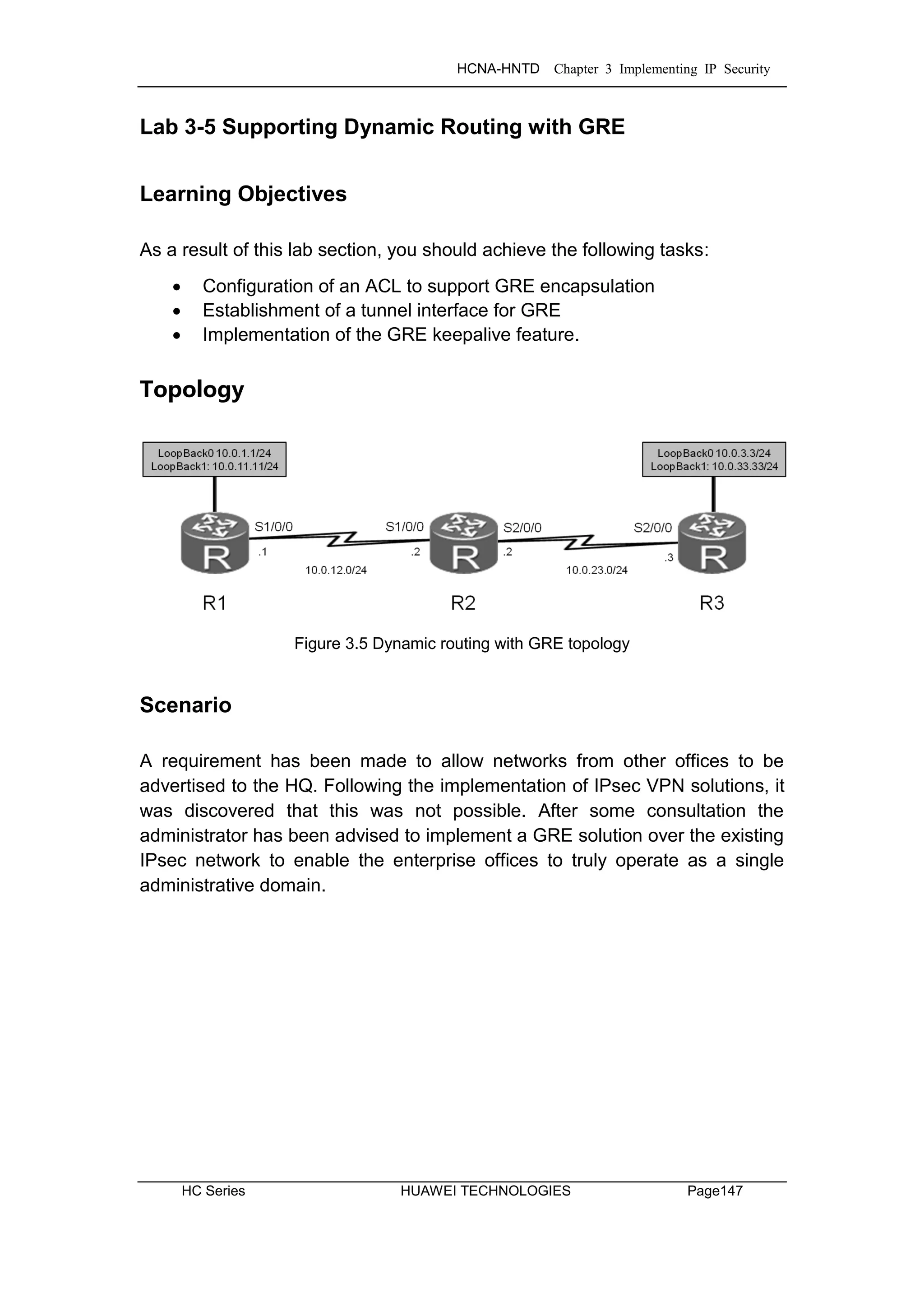
![HCNA-HNTD Chapter 3 Implementing IP Security
Page148 HUAWEI TECHNOLOGIES HC Series
Tasks
Note: It is a prerequisite that lab 3-4 be completed before attempting this lab.
Step 1 Set GRE traffic as the interesting traffic
Reconfigure the access control list establish GRE encapsulation over IPsec.
[R1]acl 3001
[R1-acl-adv-3001]rule 5 permit gre source 10.0.12.1 0 destination 10.0.23.3 0
[R3]acl 3001
[R3-acl-adv-3001]rule 5 permit gre source 10.0.23.3 0 destination 10.0.12.1 0
Step 2 Configure a tunnel interface.
Create a tunnel interface and specify GRE as the encapsulation type. Set the
tunnel source address or source interface, and set the tunnel destination
address.
[R1]interface Tunnel 0/0/1
[R1-Tunnel0/0/1]ip address 100.1.1.1 24
[R1-Tunnel0/0/1]tunnel-protocol gre
[R1-Tunnel0/0/1]source 10.0.12.1
[R1-Tunnel0/0/1]destination 10.0.23.3
[R3]interface Tunnel 0/0/1
[R3-Tunnel0/0/1]ip address 100.1.1.2 24
[R3-Tunnel0/0/1]tunnel-protocol gre
[R3-Tunnel0/0/1]source 10.0.23.3
[R3-Tunnel0/0/1]destination 10.0.12.1
Step 3 Configure a second OSPF process to route the tunnel.
Add the tunnel interface network to OSPF 1 process, and create a second
OSPF instance of the link state database (process 2) for the 10.0.12.0 and
10.0.23.0 networks, be sure to remove these networks from OSPF 1.](https://image.slidesharecdn.com/hcnaintermediatelab-190422104356/75/Hcna-intermediate-lab-156-2048.jpg)
![HCNA-HNTD Chapter 3 Implementing IP Security
HC Series HUAWEI TECHNOLOGIES Page149
[R1]ospf 1
[R1-ospf-1]area 0
[R1-ospf-1-area-0.0.0.0]network 100.1.1.0 0.0.0.255
[R1-ospf-1-area-0.0.0.0]undo network 10.0.12.0 0.0.0.255
[R1]ospf 2 router-id 10.0.1.1
[R1-ospf-2]area 0
[R1-ospf-2-area-0.0.0.0]network 10.0.12.0 0.0.0.255
[R3]ospf 1
[R3-ospf-1]area 0
[R3-ospf-1-area-0.0.0.0]network 100.1.1.0 0.0.0.255
[R3-ospf-1-area-0.0.0.0]undo network 10.0.23.0 0.0.0.255
[R3]ospf 2 router-id 10.0.3.3
[R3-ospf-2]area 0
[R3-ospf-2-area-0.0.0.0]network 10.0.23.0 0.0.0.255
OSPF LSDB are significant only to the local router, therefore allowing routes
from OSPF LSDB 2 of R1 and R3 to reach OSPF LSDB 1 of R2.
Run the display interface Tunnel 0/0/1 command to verify the configuration.
<R1>display interface Tunnel 0/0/1
Tunnel0/0/1 current state : UP
Line protocol current state : UP
Last line protocol up time : 2013-12-17 17:10:16
Description:HUAWEI, AR Series, Tunnel0/0/1 Interface
Route Port,The Maximum Transmit Unit is 1500
Internet Address is 100.1.1.1/24
Encapsulation is TUNNEL, loopback not set
Tunnel source 10.0.12.1 (Serial1/0/0), destination 10.0.23.3
Tunnel protocol/transport GRE/IP, key disabled
keepalive disabled
Checksumming of packets disabled
Current system time: 2013-12-17 17:35:39
Last 300 seconds input rate 0 bytes/sec, 0 packets/sec
Last 300 seconds output rate 9 bytes/sec, 0 packets/sec
Realtime 0 seconds input rate 0 bytes/sec, 0 packets/sec
Realtime 0 seconds output rate 0 bytes/sec, 0 packets/sec
0 packets input, 0 bytes, 0 drops
145 packets output, 14320 bytes, 0 drops
Input bandwidth utilization : --
Output bandwidth utilization : --](https://image.slidesharecdn.com/hcnaintermediatelab-190422104356/75/Hcna-intermediate-lab-157-2048.jpg)
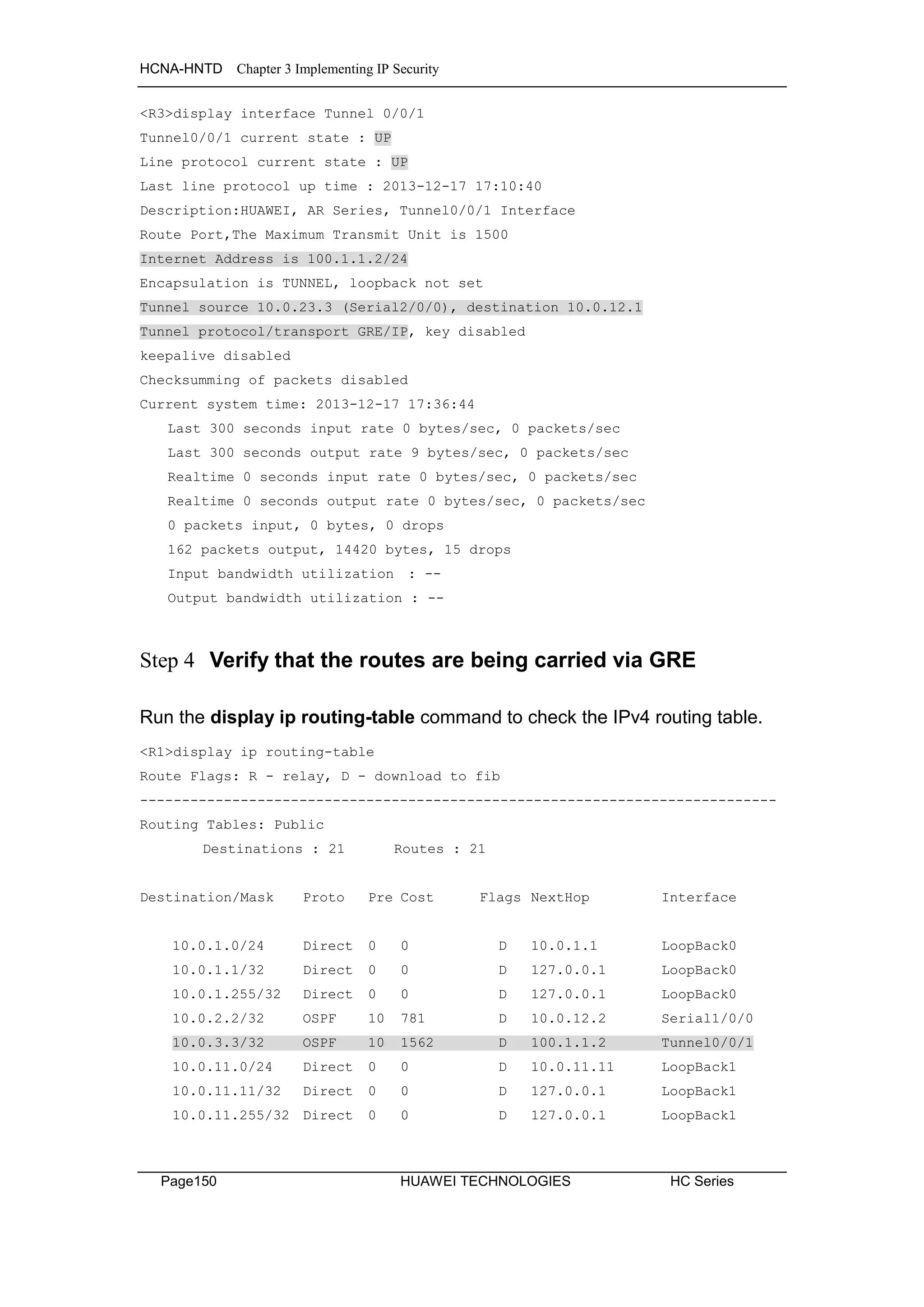
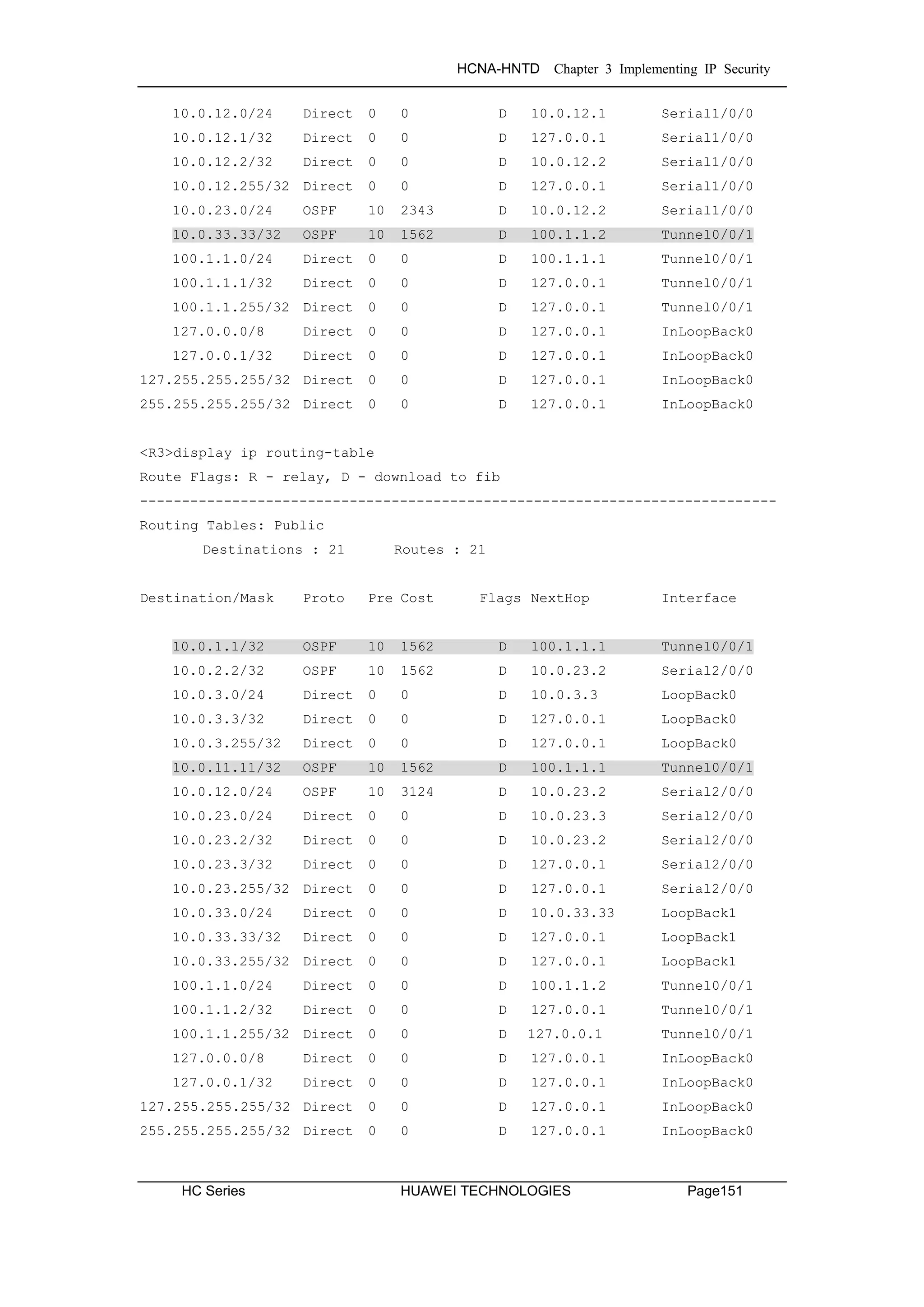
![HCNA-HNTD Chapter 3 Implementing IP Security
Page152 HUAWEI TECHNOLOGIES HC Series
After a GRE tunnel is set up, the router can exchange OSPF packets through
the GRE tunnel. Clear the IPsec statistics and test the connection
<R1>reset ipsec statistics esp
[R1]ping -a 10.0.1.1 10.0.3.3
PING 10.0.3.3: 56 data bytes, press CTRL_C to break
Reply from 10.0.3.3: bytes=56 Sequence=1 ttl=255 time=69 ms
Reply from 10.0.3.3: bytes=56 Sequence=2 ttl=255 time=70 ms
Reply from 10.0.3.3: bytes=56 Sequence=3 ttl=255 time=68 ms
Reply from 10.0.3.3: bytes=56 Sequence=4 ttl=255 time=68 ms
Reply from 10.0.3.3: bytes=56 Sequence=5 ttl=255 time=68 ms
--- 10.0.3.3 ping statistics ---
5 packet(s) transmitted
5 packet(s) received
0.00% packet loss
round-trip min/avg/max = 68/68/70 ms
<R1>display ipsec statistics esp
Inpacket count : 8
Inpacket auth count : 0
Inpacket decap count : 0
Outpacket count : 8
Outpacket auth count : 0
Outpacket encap count : 0
Inpacket drop count : 0
Outpacket drop count : 0
BadAuthLen count : 0
AuthFail count : 0
InSAAclCheckFail count : 0
PktDuplicateDrop count : 0
PktSeqNoTooSmallDrop count : 0
PktInSAMissDrop count : 0
GRE encapsulates all OSPF traffic including the hello packets over IPsec, the
gradual increment of the IPsec esp statistics verifies this.
Step 5 Implement the keepalive feature on the GRE tunnel.
[R1]interface Tunnel 0/0/1
[R1-Tunnel0/0/1]keepalive period 3](https://image.slidesharecdn.com/hcnaintermediatelab-190422104356/75/Hcna-intermediate-lab-160-2048.jpg)
![HCNA-HNTD Chapter 3 Implementing IP Security
HC Series HUAWEI TECHNOLOGIES Page153
Verify that the keepalive feature has been enabled on the tunnel interface.
<R1>display interface Tunnel 0/0/1
Tunnel0/0/1 current state : UP
Line protocol current state : UP
Last line protocol up time : 2013-12-18 09:50:21
Description:HUAWEI, AR Series, Tunnel0/0/1 Interface
Route Port,The Maximum Transmit Unit is 1500
Internet Address is 100.1.1.1/24
Encapsulation is TUNNEL, loopback not set
Tunnel source 10.0.12.1 (Serial1/0/0), destination 10.0.23.3
Tunnel protocol/transport GRE/IP, key disabled
keepalive enable period 3 retry-times 3
Checksumming of packets disabled
Current system time: 2013-12-18 11:05:49
Last 300 seconds input rate 0 bytes/sec, 0 packets/sec
Last 300 seconds output rate 8 bytes/sec, 0 packets/sec
Realtime 0 seconds input rate 0 bytes/sec, 0 packets/sec
Realtime 0 seconds output rate 0 bytes/sec, 0 packets/sec
0 packets input, 0 bytes, 0 drops
503 packets output, 47444 bytes, 0 drops
Input bandwidth utilization : --
Output bandwidth utilization : --
Final Configuration
<R1>display current-configuration
[V200R003C00SPC200]
#
sysname R1
#
acl number 3001
rule 5 permit gre source 10.0.12.1 0 destination 10.0.23.3 0
#
ipsec proposal tran1
esp authentication-algorithm sha1
esp encryption-algorithm 3des
#
ipsec policy P1 10 manual
security acl 3001
proposal tran1](https://image.slidesharecdn.com/hcnaintermediatelab-190422104356/75/Hcna-intermediate-lab-161-2048.jpg)

![HCNA-HNTD Chapter 3 Implementing IP Security
HC Series HUAWEI TECHNOLOGIES Page155
#
return
<R2>display current-configuration
[V200R003C00SPC200]
#
sysname R2
#
interface Serial1/0/0
link-protocol ppp
ppp pap local-user huawei password cipher %$%$u[hr6d<JVHR@->T7xr1<$.iv%$%$
ip address 10.0.12.2 255.255.255.0
#
interface Serial2/0/0
link-protocol ppp
ppp chap user huawei
ppp chap password cipher %$%$e{5h)gh"/Uz0mUC%vEx3$4<m%$%$
ip address 10.0.23.2 255.255.255.0
#
interface LoopBack0
ip address 10.0.2.2 255.255.255.0
#
ospf 1 router-id 10.0.2.2
area 0.0.0.0
network 10.0.2.0 0.0.0.255
network 10.0.12.0 0.0.0.255
network 10.0.23.0 0.0.0.255
#
user-interface con 0
authentication-mode password
set authentication password
cipher %$%$|nRPL^hr2IXi7LHDID!/,.*%.8%h;3:,hXO2dk#ikaWI.*(,%$%$
user-interface vty 0 4
#
return
<R3>display current-configuration
[V200R003C00SPC200]
#
sysname R3
#](https://image.slidesharecdn.com/hcnaintermediatelab-190422104356/75/Hcna-intermediate-lab-163-2048.jpg)


![HCNA-HNTD Chapter 4 Managing Enterprise Networks
HC Series HUAWEI TECHNOLOGIES Page159
Tasks
Step 1 Preparing the environment
If you are starting this section with a non-configured device, begin here and
then move to step 3. For those continuing from previous labs, begin at step 2.
<Huawei>system-view
[Huawei]sysname R1
[R1]interface LoopBack 0
[R1-LoopBack0]ip address 10.0.1.1 24
<Huawei>system-view
[Huawei]sysname R3
[R3]interface LoopBack 0
[R3-LoopBack0]ip address 10.0.3.3 24
Step 2 Clean up the previous configuration
Disable the unused serial interfaces and remove the OSPF processes from all
routers.
[R1]interface Serial 1/0/0
[R1-Serial1/0/0]shutdown
[R1-Serial1/0/0]quit
[R1]undo ospf 1
Warning: The OSPF process will be deleted. Continue? [Y/N]:y
[R1]undo ospf 2
Warning: The OSPF process will be deleted. Continue? [Y/N]:y
[R3]interface Serial 2/0/0
[R3-Serial2/0/0]shutdown
[R3-Serial2/0/0]quit
[R3]undo ospf 1
Warning: The OSPF process will be deleted. Continue? [Y/N]:y
[R3]undo ospf 2
Warning: The OSPF process will be deleted. Continue? [Y/N]:y](https://image.slidesharecdn.com/hcnaintermediatelab-190422104356/75/Hcna-intermediate-lab-167-2048.jpg)
![HCNA-HNTD Chapter 4 Managing Enterprise Networks
Page160 HUAWEI TECHNOLOGIES HC Series
Step 3 Estabish routes between hosts and the NMS.
Configure the IP address and route on the router, make sure the route
between the device and the NMS is reachable.
[R1]interface GigabitEthernet 0/0/0
[R1-GigabitEthernet0/0/0]ip address 10.0.13.1 24
[R3]interface GigabitEthernet 0/0/0
[R3-GigabitEthernet0/0/0]ip address 10.0.13.3 24
[R1]ospf
[R1]ospf 1 router-id 10.0.1.1
[R1-ospf-1]area 0
[R1-ospf-1-area-0.0.0.0]network 10.0.1.0 0.0.0.255
[R1-ospf-1-area-0.0.0.0]network 10.0.13.0 0.0.0.255
[R3]ospf 1 router-id 10.0.3.3
[R3-ospf-1]area 0
[R3-ospf-1-area-0.0.0.0]network 10.0.3.0 0.0.0.255
[R3-ospf-1-area-0.0.0.0]network 10.0.13.0 0.0.0.255
Test the network connectivity.
[R1]ping 10.0.13.254
PING 10.0.13.254: 56 data bytes, press CTRL_C to break
Reply from 10.0.13.254: bytes=56 Sequence=1 ttl=128 time=1 ms
Reply from 10.0.13.254: bytes=56 Sequence=2 ttl=128 time=1 ms
Reply from 10.0.13.254: bytes=56 Sequence=3 ttl=128 time=10 ms
Reply from 10.0.13.254: bytes=56 Sequence=4 ttl=128 time=1 ms
Reply from 10.0.13.254: bytes=56 Sequence=5 ttl=128 time=1 ms
--- 10.0.13.254 ping statistics ---
5 packet(s) transmitted
5 packet(s) received
0.00% packet loss
round-trip min/avg/max = 1/2/10 ms](https://image.slidesharecdn.com/hcnaintermediatelab-190422104356/75/Hcna-intermediate-lab-168-2048.jpg)
![HCNA-HNTD Chapter 4 Managing Enterprise Networks
HC Series HUAWEI TECHNOLOGIES Page161
Step 4 Configure SNMP on R1.
Enable the SNMP agent and confige the version SNMPv2c on the R1.
[R1]snmp-agent
[R1]snmp-agent sys-info version v2c
Configure SNMP read and write community
[R1]snmp-agent community read public
[R1]snmp-agent community write private
Enable the trap function of R1. Configure contact information about the
device administrator.
[R1]snmp-agent trap enable
Info: All switches of SNMP trap/notification will be open. Continue? [Y/N]:y
[R1]snmp-agent trap queue-size 200
[R1]snmp-agent trap life 60
[R1]snmp-agent target-host trap-hostname NMS address 10.0.13.254 trap-paramsname
public
[R1]snmp-agent target-host trap-paramsname public v2c securityname public
[R1]snmp-agent sys-info contact Call the operator at 010-12345678
After the configuration is complete, run the following commands to verify that
the configuration has taken effect.
<R1>display snmp-agent sys-info
The contact person for this managed node:
Call the operator at 010-12345678
The physical location of this node:
Shenzhen China
SNMP version running in the system:
SNMPv2c
<R1>display snmp-agent community write
Community name: %$%$ZR)y~^VY9I"~n`=b`KR1(OX%%$%$
Storage type: nonVolatile
View name: ViewDefault](https://image.slidesharecdn.com/hcnaintermediatelab-190422104356/75/Hcna-intermediate-lab-169-2048.jpg)


![HCNA-HNTD Chapter 4 Managing Enterprise Networks
Page164 HUAWEI TECHNOLOGIES HC Series
Select the Telnet Parameters option under Protocol Parameters of the
resource menu, to configure the telnet parameters for accessing each network
element from the NMS. If the AAA local user authentication of lab 7-3 has been
maintained in the current configuration, it can be applied as shown. Note: the
password is huawei.
Optionally, if the AAA authentication is not present on the VTY interface of R1
and/or R3, a simple telnet authentication process can be applied as follows
before registering the telnet parameters in the NMS.
[R1]user-interface vty 0 4
[R1-ui-vty0-4]authentication-mode password
[R1-ui-vty0-4]set authentication password cipher huawei
[R1-ui-vty0-4]user privilege level 0
The telnet feature in the Basic Information panel of the resource menu grants
remote management of the NE via the NMS, however privileges currently
prevent configuration.](https://image.slidesharecdn.com/hcnaintermediatelab-190422104356/75/Hcna-intermediate-lab-172-2048.jpg)
![HCNA-HNTD Chapter 4 Managing Enterprise Networks
HC Series HUAWEI TECHNOLOGIES Page165
If the AAA configuration has been maintained from lab 7-3, first increase the
privilege from level 0 to level 3.
[R1]aaa
[R1-aaa]local-user user1@huawei privilege level 3
Alternatively, if the simple telnet authentication process has been used,
change the privilege on the VTY user interface.
[R1-ui-vty0-4]user privilege level 3
Step 6 Manage Basic NMS Trap Functions
Changes that occur to the NE can be monitored in the NMS using traps which
trigger alarms. Select the Alarm List from the view panel from the resource
menu .
Currently no alarms are recorded. Access the NE through the telnet feature in
the NMS and shut down the loopback 0 interface to trigger alarms on the NMS.
[R1]interface LoopBack 0
[R1-LoopBack0]shutdown
[R1-LoopBack0]undo shutdown](https://image.slidesharecdn.com/hcnaintermediatelab-190422104356/75/Hcna-intermediate-lab-173-2048.jpg)
![HCNA-HNTD Chapter 4 Managing Enterprise Networks
Page166 HUAWEI TECHNOLOGIES HC Series
Verify that the relevant alarms have been generated in the Alarm List for the
resource, once the interface state has been changed.
Additional Exercises: Analyzing and Verifying
If the interface of R1 that is linked to the NMS is down, will the failure be
detected by the NMS?
Final Configuration
<R1>dis current-configuration
[V200R003C00SPC200]
#
sysname R1
#
snmp-agent local-engineid 800007DB0354899876830A
snmp-agent community read %$%$><Oc4D:9(4}bjw"Bu'd7(ONp%$%$
snmp-agent community write %$%$ZR)y~^VY9I"~n`=b`KR1(OX%%$%$
snmp-agent sys-info contact Call the operator at 010-12345678
snmp-agent sys-info version v2c
snmp-agent target-host trap-hostname NMS address 10.0.13.254 udp-port 162
trap-paramsname public
snmp-agent target-host trap-paramsname public v2c securityname public
snmp-agent trap enable
snmp-agent trap queue-size 200
snmp-agent trap life 60
snmp-agent
#
aaa
authentication-scheme default
authentication-scheme auth1
authorization-scheme default
authorization-scheme auth2
accounting-scheme default
domain default
domain default_admin
domain huawei](https://image.slidesharecdn.com/hcnaintermediatelab-190422104356/75/Hcna-intermediate-lab-174-2048.jpg)
![HCNA-HNTD Chapter 4 Managing Enterprise Networks
HC Series HUAWEI TECHNOLOGIES Page167
authentication-scheme auth1
authorization-scheme auth2
local-user admin password cipher %$%$=i~>Xp&aY+*2cEVcS-A23Uwe%$%$
local-user admin service-type http
local-user huawei password cipher %$%$B:%I)Io0H8)[%SB[idM3C/!#%$%$
local-user huawei service-type ppp
local-user user1@huawei password cipher %$%$^L*5IP'0^A!;R)R*L=LFcXgv%$%$
local-user user1@huawei privilege level 3
local-user user1@huawei service-type telnet
#
interface GigabitEthernet0/0/0
ip address 10.0.13.1 255.255.255.0
#
interface LoopBack0
ip address 10.0.1.1 255.255.255.0
#
ospf 1 router-id 10.0.1.1
area 0.0.0.0
network 10.0.1.0 0.0.0.255
network 10.0.13.0 0.0.0.255
#
user-interface con 0
authentication-mode password
set authentication password
cipher %$%$dD#}P<HzJ;Xs%X>hOkm!,.+Iq61QK`K6tI}cc-;k_o`C.+L,%$%$
user-interface vty 0 4
authentication-mode aaa
#
return
<R3>display current-configuration
[V200R003C00SPC200]
#
sysname R3
#
snmp-agent local-engineid 800007DB03548998768222
snmp-agent community read %$%$I^)/SB#f|Q#U*Fd^xVX(bwT%$%$
snmp-agent community write %$%$,CnkQV6[!*c.&0/wn>HU(b{n%$%$
snmp-agent sys-info contact Call the operator at 010-12345678
snmp-agent sys-info version v2c
snmp-agent target-host trap-hostname NMS address 10.0.13.254 udp-port 162
trap-paramsname public](https://image.slidesharecdn.com/hcnaintermediatelab-190422104356/75/Hcna-intermediate-lab-175-2048.jpg)
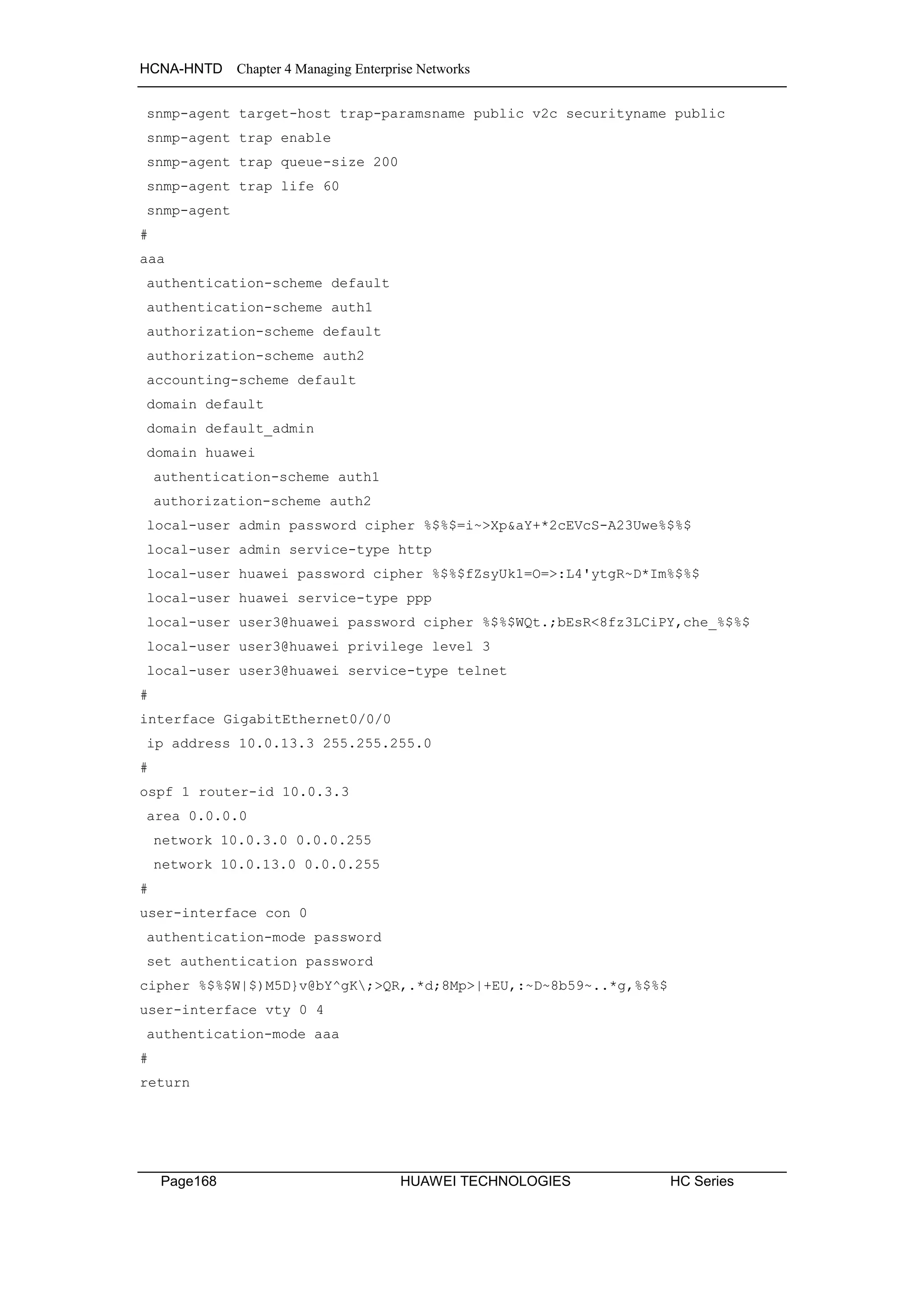

![HCNA-HNTD Chapter 5 Establishing IPv6 Networks
Page170 HUAWEI TECHNOLOGIES HC Series
Scenario
In line with plans for deployment of solutions for next generation networks, it
has been decided that the enterprise network should implement an IPv6
design to the existing infrastructure. As the administrator you have been
tasked with the job of implementing the addressing scheme and routing for
IPv6, as well as providing stateful addressing solutions for IPv6.
Tasks
Step 1 Preparing the environment
If you are starting this section with a non-configured device, begin here and
then move to step 2. For those continuing from previous labs, begin at step 2.
<huawei>system-view
[huawei]sysname R1
<huawei>system-view
[huawei]sysname R2
<huawei>system-view
[huawei]sysname R3
Step 2 Configure IPv6 addressing
Establish IPv6 global unicast addressing on the loopback interfaces and
manually configure link local addressing on interface Gigabit Ethernet 0/0/0 of
all routers.
[R1]ipv6
[R1]interface loopback 0
[R1-LoopBack0]ipv6 enable
[R1-LoopBack0]ipv6 address 2001:1::A 64
[R1]interface GigabitEthernet 0/0/0
[R1-GigabitEthernet0/0/0]ipv6 enable
[R1-GigabitEthernet0/0/0]ipv6 address fe80::1 link-local](https://image.slidesharecdn.com/hcnaintermediatelab-190422104356/75/Hcna-intermediate-lab-178-2048.jpg)
![HCNA-HNTD Chapter 5 Establishing IPv6 Networks
HC Series HUAWEI TECHNOLOGIES Page171
[R2]ipv6
[R2]interface loopback 0
[R2-LoopBack0]ipv6 enable
[R2-LoopBack0]ipv6 address 2001:2::B 64
[R2]interface GigabitEthernet 0/0/0
[R2-GigabitEthernet0/0/0]ipv6 enable
[R2-GigabitEthernet0/0/0]ipv6 address fe80::2 link-local
[R3]ipv6
[R3]interface loopback 0
[R3-LoopBack0]ipv6 enable
[R3-LoopBack0]ipv6 address 2001:3::C 64
[R3]interface GigabitEthernet 0/0/0
[R3-GigabitEthernet0/0/0]ipv6 enable
[R3-GigabitEthernet0/0/0]ipv6 address fe80::3 link-local
<R1>display ipv6 interface GigabitEthernet 0/0/0
GigabitEthernet0/0/0 current state : UP
IPv6 protocol current state : UP
IPv6 is enabled, link-local address is FE80::1
No global unicast address configured
Joined group address(es):
FF02::1:FF00:1
FF02::2
FF02::1
MTU is 1500 bytes
ND DAD is enabled, number of DAD attempts: 1
ND reachable time is 30000 milliseconds
ND retransmit interval is 1000 milliseconds
Hosts use stateless autoconfig for addresses
IPv6 interfaces become part of various multicast groups for support of
stateless address auto-configuration (SLAAC). The Network Discovery (ND)
Duplicate Address Detection (DAD) verifies the link local address is unique.](https://image.slidesharecdn.com/hcnaintermediatelab-190422104356/75/Hcna-intermediate-lab-179-2048.jpg)
![HCNA-HNTD Chapter 5 Establishing IPv6 Networks
Page172 HUAWEI TECHNOLOGIES HC Series
Step 3 Configure OSPFv3.
Enable the OSPFv3 process and specify its router ID on R1, R2 and R3.
OSPFv3 must then be enabled on the interface.
[R1]ospfv3 1
[R1-ospfv3-1]router-id 1.1.1.1
[R1-ospfv3-1]quit
[R1]interface GigabitEthernet 0/0/0
[R1-GigabitEthernet0/0/0]ospfv3 1 area 0
[R1-GigabitEthernet0/0/0]quit
[R1]interface loopback 0
[R1-LoopBack0]ospfv3 1 area 0
[R2]ospfv3 1
[R2-ospfv3-1]router-id 2.2.2.2
[R2-ospfv3-1]quit
[R2]interface GigabitEthernet 0/0/0
[R2-GigabitEthernet0/0/0]ospfv3 1 area 0
[R2-GigabitEthernet0/0/0]quit
[R2]interface loopback 0
[R2-LoopBack0]ospfv3 1 area 0
[R3]ospfv3 1
[R3-ospfv3-1]router-id 3.3.3.3
[R3-ospfv3-1]quit
[R3]interface GigabitEthernet 0/0/0
[R3-GigabitEthernet0/0/0]ospfv3 1 area 0
[R3-GigabitEthernet0/0/0]quit
[R3]interface loopback 0
[R3-LoopBack0]ospfv3 1 area 0
Run the display ospfv3 peer command on R1 and R3 to verify the OSPFv3
peering has been established.
<R1>display ospfv3 peer
OSPFv3 Process (1)
OSPFv3 Area (0.0.0.0)
Neighbor ID Pri State Dead Time Interface Instance ID
2.2.2.2 1 Full/Backup 00:00:30 GE0/0/0 0
3.3.3.3 1 Full/DROther 00:00:40 GE0/0/0 0](https://image.slidesharecdn.com/hcnaintermediatelab-190422104356/75/Hcna-intermediate-lab-180-2048.jpg)

![HCNA-HNTD Chapter 5 Establishing IPv6 Networks
Page174 HUAWEI TECHNOLOGIES HC Series
bytes=56 Sequence=4 hop limit=64 time = 2 ms
Reply from 2001:3::C
bytes=56 Sequence=5 hop limit=64 time = 6 ms
--- 2001:3::C ping statistics ---
5 packet(s) transmitted
5 packet(s) received
0.00% packet loss
round-trip min/avg/max = 2/5/11 ms
Step 4 Configure DHCPv6 to distribute IPv6 addresses.
Enable the DHCPv6 Server function on R2 so that devices can be assigned
IPv6 addresses using DHCPv6.
[R2]dhcp enable
[R2]dhcpv6 pool pool1
[R2-dhcpv6-pool-pool1]address prefix 2001:FACE::/64
[R2-dhcpv6-pool-pool1]dns-server 2001:444e:5300::1
[R2-dhcpv6-pool-pool1]excluded-address 2001:FACE::1
[R2-dhcpv6-pool-pool1]quit
Configure IPv6 functions on the GigabitEthernet 0/0/0 interface.
Enable the DHCPv6 server function on the interface.
[R2]interface GigabitEthernet 0/0/0
[R2-GigabitEthernet0/0/0]ipv6 address 2001:FACE::1 64
[R2-GigabitEthernet0/0/0]dhcpv6 server pool1
Enable the DHCPv6 client function on R1 and R3 so that devices can obtain
IPv6 addresses using DHCPv6.
[R1]dhcp enable
[R1]interface gigabitethernet 0/0/0
[R1-GigabitEthernet0/0/0]ipv6 address auto dhcp
[R3]dhcp enable
[R3]interface GigabitEthernet 0/0/0
[R3-GigabitEthernet0/0/0]ipv6 address auto dhcp](https://image.slidesharecdn.com/hcnaintermediatelab-190422104356/75/Hcna-intermediate-lab-182-2048.jpg)
![HCNA-HNTD Chapter 5 Establishing IPv6 Networks
HC Series HUAWEI TECHNOLOGIES Page175
Run the display dhcpv6 pool command on R2 to check information about the
DHCPv6 address pool.
<R2>display dhcpv6 pool
DHCPv6 pool: pool1
Address prefix: 2001:FACE::/64
Lifetime valid 172800 seconds, preferred 86400 seconds
2 in use, 0 conflicts
Excluded-address 2001:FACE::1
1 excluded addresses
Information refresh time: 86400
DNS server address: 2001:444E:5300::1
Conflict-address expire-time: 172800
Active normal clients: 2
Run the display ipv6 interface brief command on R1 and R3 to check the
IPv6 address information.
[R1]display ipv6 interface brief
*down: administratively down
(l): loopback
(s): spoofing
Interface Physical Protocol
GigabitEthernet0/0/0 up up
[IPv6 Address] 2001:FACE::2
LoopBack0 up up(s)
[IPv6 Address] 2001:1::A
[R3]display ipv6 interface brief
*down: administratively down
(l): loopback
(s): spoofing
Interface Physical Protocol
GigabitEthernet0/0/0 up up
[IPv6 Address] 2001:FACE::3
LoopBack0 up up(s)
[IPv6 Address] 2001:3::C](https://image.slidesharecdn.com/hcnaintermediatelab-190422104356/75/Hcna-intermediate-lab-183-2048.jpg)
![HCNA-HNTD Chapter 5 Establishing IPv6 Networks
Page176 HUAWEI TECHNOLOGIES HC Series
Final Configuration
<R1>display current-configuration
[V200R003C00SPC200]
#
sysname R1
#
ipv6
#
dhcp enable
#
ospfv3 1
router-id 1.1.1.1
#
interface GigabitEthernet0/0/0
ipv6 enable
ip address 10.0.13.1 255.255.255.0
ipv6 address FE80::1 link-local
ospfv3 1 area 0.0.0.0
ipv6 address auto dhcp
#
interface LoopBack0
ipv6 enable
ip address 10.0.1.1 255.255.255.0
ipv6 address 2001:1::A/64
ospfv3 1 area 0.0.0.0
#
user-interface con 0
authentication-mode password
set authentication password
cipher %$%$dD#}P<HzJ;Xs%X>hOkm!,.+Iq61QK`K6tI}cc-;k_o`C.+L,%$%$
user-interface vty 0 4
authentication-mode aaa
#
return](https://image.slidesharecdn.com/hcnaintermediatelab-190422104356/75/Hcna-intermediate-lab-184-2048.jpg)
![HCNA-HNTD Chapter 5 Establishing IPv6 Networks
HC Series HUAWEI TECHNOLOGIES Page177
<R2>display current-configuration
[V200R003C00SPC200]
#
sysname R2
#
ipv6
#
dhcp enable
#
dhcpv6 pool pool1
address prefix 2001:FACE::/64
excluded-address 2001:FACE::1
dns-server 2001:444E:5300::1
#
ospfv3 1
router-id 2.2.2.2
#
interface GigabitEthernet0/0/0
ipv6 enable
ip address 10.0.13.2 255.255.255.0
ipv6 address 2001:FACE::1/64
ipv6 address FE80::2 link-local
ospfv3 1 area 0.0.0.0
traffic-filter inbound acl 3000
dhcpv6 server pool1
#
interface LoopBack0
ipv6 enable
ip address 10.0.2.2 255.255.255.0
ipv6 address 2001:2::B/64
ospfv3 1 area 0.0.0.0
#
user-interface con 0
authentication-mode password
set authentication password
cipher %$%$|nRPL^hr2IXi7LHDID!/,.*%.8%h;3:,hXO2dk#ikaWI.*(,%$%$
user-interface vty 0 4
#
return](https://image.slidesharecdn.com/hcnaintermediatelab-190422104356/75/Hcna-intermediate-lab-185-2048.jpg)
![HCNA-HNTD Chapter 5 Establishing IPv6 Networks
Page178 HUAWEI TECHNOLOGIES HC Series
<R3>display current-configuration
[V200R003C00SPC200]
#
sysname R3
#
ipv6
#
dhcp enable
#
ospfv3 1
router-id 3.3.3.3
#
interface GigabitEthernet0/0/0
ipv6 enable
ip address 10.0.13.3 255.255.255.0
ipv6 address FE80::3 link-local
ospfv3 1 area 0.0.0.0
ipv6 address auto dhcp
#
interface LoopBack0
ipv6 enable
ip address 10.0.3.3 255.255.255.0
ipv6 address 2001:3::C/64
ospfv3 1 area 0.0.0.0
#
user-interface con 0
authentication-mode password
set authentication password
cipher %$%$W|$)M5D}v@bY^gK;>QR,.*d;8Mp>|+EU,:~D~8b59~..*g,%$%$
user-interface vty 0 4
authentication-mode aaa
#
return](https://image.slidesharecdn.com/hcnaintermediatelab-190422104356/75/Hcna-intermediate-lab-186-2048.jpg)


![MPLS L3 VPN Tutorial, by Nurul Islam Roman [APNIC 38]](https://cdn.slidesharecdn.com/ss_thumbnails/mplsl3vpnapnic381410820509-140915192004-phpapp02-thumbnail.jpg?width=640&height=640&fit=bounds)