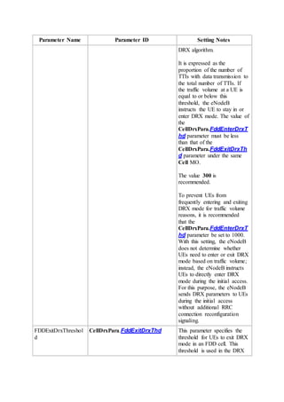
Downloaded 232 times

![3.4.2 Startup of a DRX Cycle
After the UE enters DRX mode, the On Duration Timer may not start immediately. The timer
starts up and the UE starts a long or short DRX cycle only when the following conditions are
met:
For a long DRX cycle:
[(SFN x 10) + SSFN] modulo DrxParaGroup.LongDRXCycle = DRX start offset
The long DRX cycle starts at the time specified by the system frame number (SFN) or
system subframe number (SSFN).
For a short DRX cycle:
[(SFN x 10) + SSFN] modulo DrxParaGroup.ShortDRXCycle = (DRX start offset)
modulo DrxParaGroup.ShortDRXCycle
The short DRX cycle starts at the time specified by the SFN or SSFN.
NOTE:
These formulas are defined in section 5.7 "Discontinuous Reception (DRX)" of 3GPP TS
36.321 V10.5.0.
In these formulas, DRX start offset is the start offset of the long DRX cycle, and (DRX start
offset) modulo DrxParaGroup.ShortDRXCycle is the start offset of the short DRX cycle.
The eNodeB notifies the UE of the long DRX cycle, short DRX cycle, and DRX start offset
in the RRC Connection Reconfiguration message.
If the DrxParaGroup.ShortDRXCycle parameter is set, the value of the LongDrxCycle
parameter must be an integer multiple of the value of the DrxParaGroup.ShortDRXCycle
parameter.
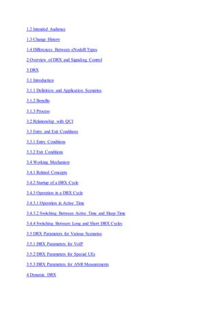
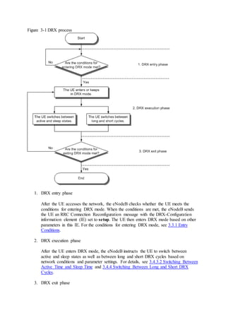
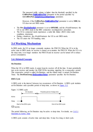
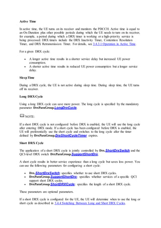
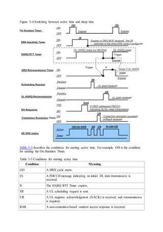
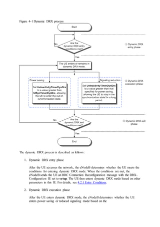
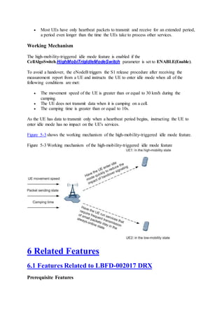
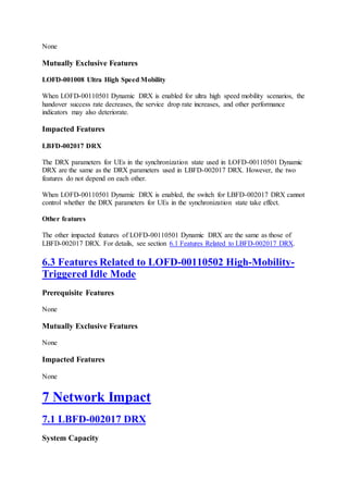
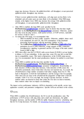
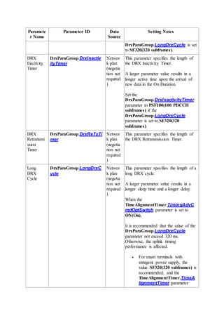
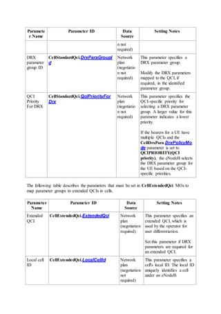
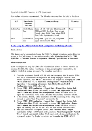
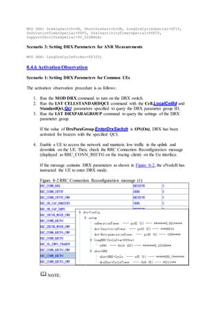
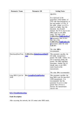
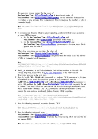
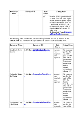
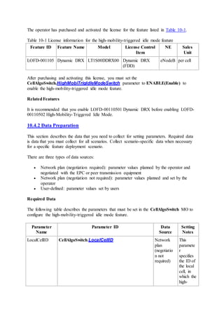
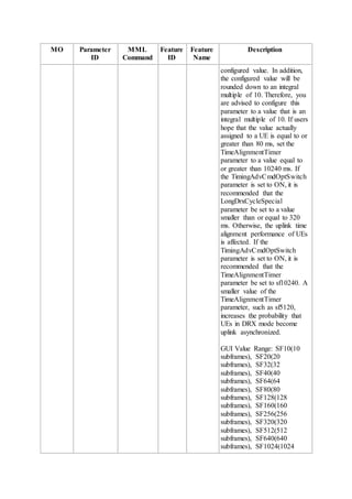
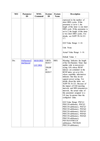
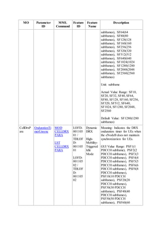
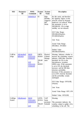
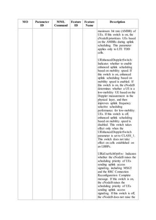
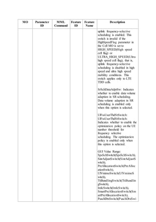
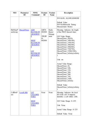
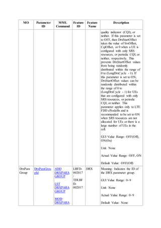
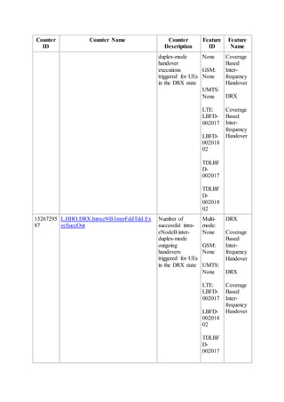
Figure 3-3 shows how the UE enters DRX mode. The eNodeB assigns the same long DRX
cycle of 10 transmission time intervals (TTIs) to both UE 1 and UE 2 in radio frame 0 (whose
SFN is 0) in a cell and instructs them to enter DRX mode respectively at TTI 1 and TTI 0.
UE 1 and UE 2 enter the DRX cycle respectively at TTI 3 and TTI 4, based on the configured
DRX start offset. Therefore, for UE 1, (SFN, SSFN) = (0, 3); for UE 2, (SFN, SSFN) = (0, 4).](https://image.slidesharecdn.com/drx-160511085952/85/Drx-19-320.jpg)

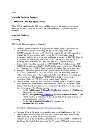
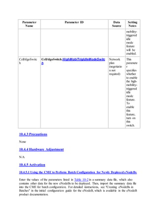
![Movement Speed (km/h) Camping Time (Seconds)
[30-60] [18-36]
[60-120] [18-9]
> 120 < 9
Table 5-2 Movement speed and camping time of a UE in a cell with a radius of 500 m
Movement Speed (km/h) Camping Time (Seconds)
[30-60] [30-60]
[60-120] [15-30]
> 120 < 15
In reality, most UEs do not pass through the cell center and the camping time of these UEs is
even shorter.
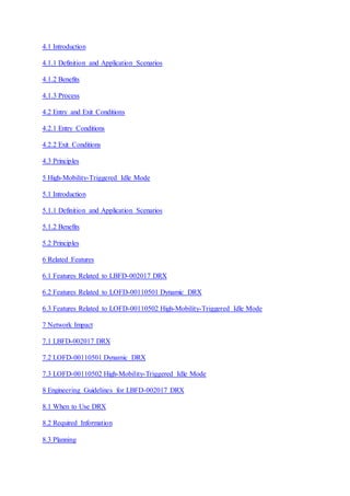
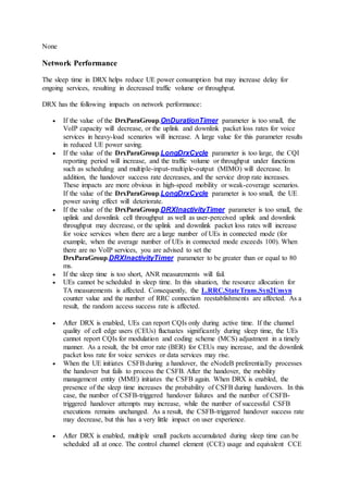
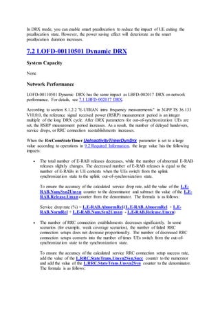
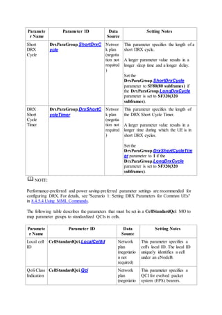
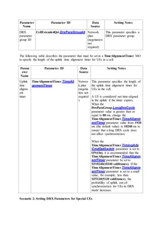
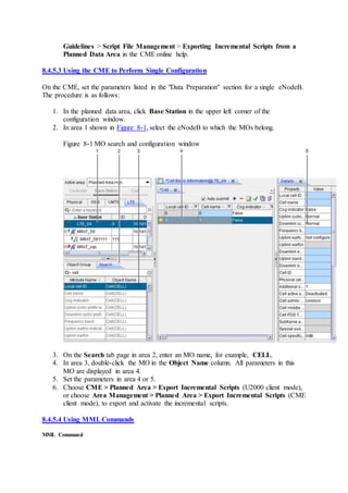
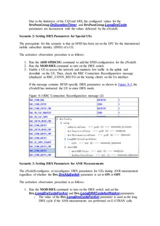
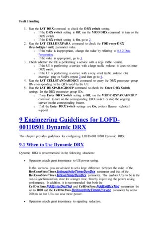
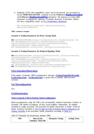
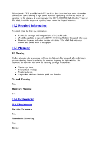
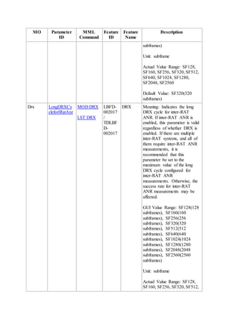
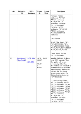
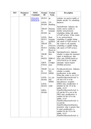
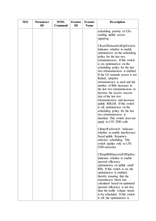
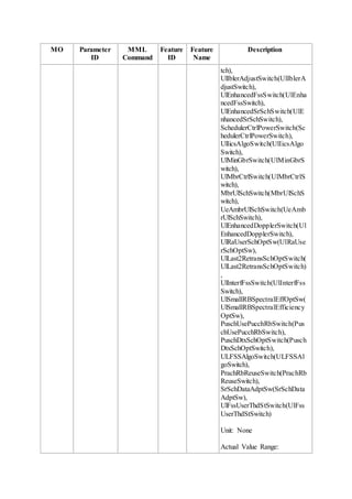
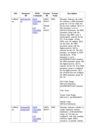
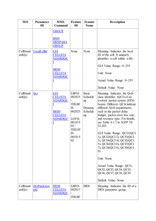
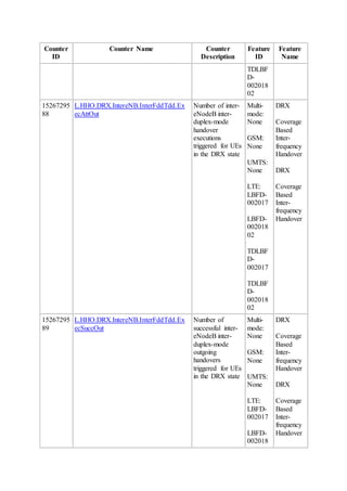
Figure 5-2 shows the numbers of service requests triggered by heartbeats.
Figure 5-2 Numbers of service requests triggered by heartbeats
In Figure 5-2, the x-axis specifies the service types and the y-axis specifies the number of
network access requests triggered by heartbeats within an hour. The heartbeat period is equal
to 3600 divided by the number of service requests.
You can extrapolate the following from the data shown in Figure 5-2:
The heartbeat periods for most services are 180s or longer.
In each heartbeat period, the UE stays in connected mode for a long time.
During a heartbeat period, if the UE is moving fast, it may pass through several cells
and be handed over many times. For example, during a heartbeat period of 180s, a UE
moving at 30 km/h may pass through five 300 m radius cells. If the UE stays in
connected mode in this period, multiple handovers will be performed. During this
process, no service data is transmitted.](https://image.slidesharecdn.com/drx-160511085952/85/Drx-41-320.jpg)


This document describes discontinuous reception (DRX) and signaling control features for LTE networks, including DRX, dynamic DRX, and high-mobility-triggered idle mode. It provides an overview of these features, their technical principles, related features, network impacts, and engineering guidelines. The document contains detailed sections on DRX parameters for various scenarios, dynamic DRX principles, and deployment and maintenance guidelines.


