Cryogenic rocket engines use cryogenic, or very cold liquefied gases, as propellants. They are typically fueled by liquid hydrogen and liquid oxygen which must be stored at temperatures below -423°F and -297°F respectively to remain in liquid form. Cryogenic engines offer advantages like being able to control and restart the fuel flow, but require complex turbopumps and thermal insulation to handle the extreme cold temperatures. Major components include thrust chambers, fuel injectors, turbopumps, igniters, valves, tanks, and de Laval nozzles. The Space Shuttle's main engines were cryogenic, using this technology to produce high exhaust velocities and thrust.
![Cryogenic rocket engine and propellents
Rocket engine
A rocket engine, or simply "rocket", is a jet engine[1] that uses only propellant mass for forming
its high speed propulsive jet. Rocket engines are reaction engines and obtain thrust in
accordance with Newton's third law. Since they need no external material to form their
jet, rocket engines can be used for spacecraft propulsion as well as terrestrial uses, such
as missiles. Most rocket engines are internal combustion engines, although non combusting
forms also exist.
Rocket engines as a group have the highest exhaust velocities, are by far the lightest, but are the
least propellant efficient of all types of jet engines.
Types of rocket engines
Rocket motor (or solid-propellant rocket motor) is a synonymous term with rocket engine that
usually refers to solid rocket engines.
Liquid rockets (or liquid-propellant rocket engine) use one or more liquid propellants that are
held in tanks prior to burning.
Hybrid rockets have a solid propellant in the combustion chamber and a second liquid or gas
propellant is added to permit it to burn.
Thermal rockets are rockets where the propellant is inert, but is heated by a power source such
as solar or nuclear power or beamed energy.
Monopropellant rockets are rockets where the propellant is one chemical, typically hi-test
(85%+) hydrogen peroxide, which is decomposed by a catalyst producing steam and oxygen.
There is no flame.
Liquid-propellant rocket
A liquid-propellant rocket or a liquid rocket is a rocket engine that
uses propellants in liquid form. Liquids are desirable because their reasonably high density allows
the volume of the propellant tanks to be relatively low, and it is possible to use lightweight pumps
to pump the propellant from the tanks into the engines, which means that the propellants can be
kept under low pressure. This permits the use of low mass propellant tanks, permitting a
high mass ratio for the rocket.](https://image.slidesharecdn.com/cryogenic-rocket-engine-propellents-180426042953/75/Cryogenic-rocket-engine-propellents-1-2048.jpg)


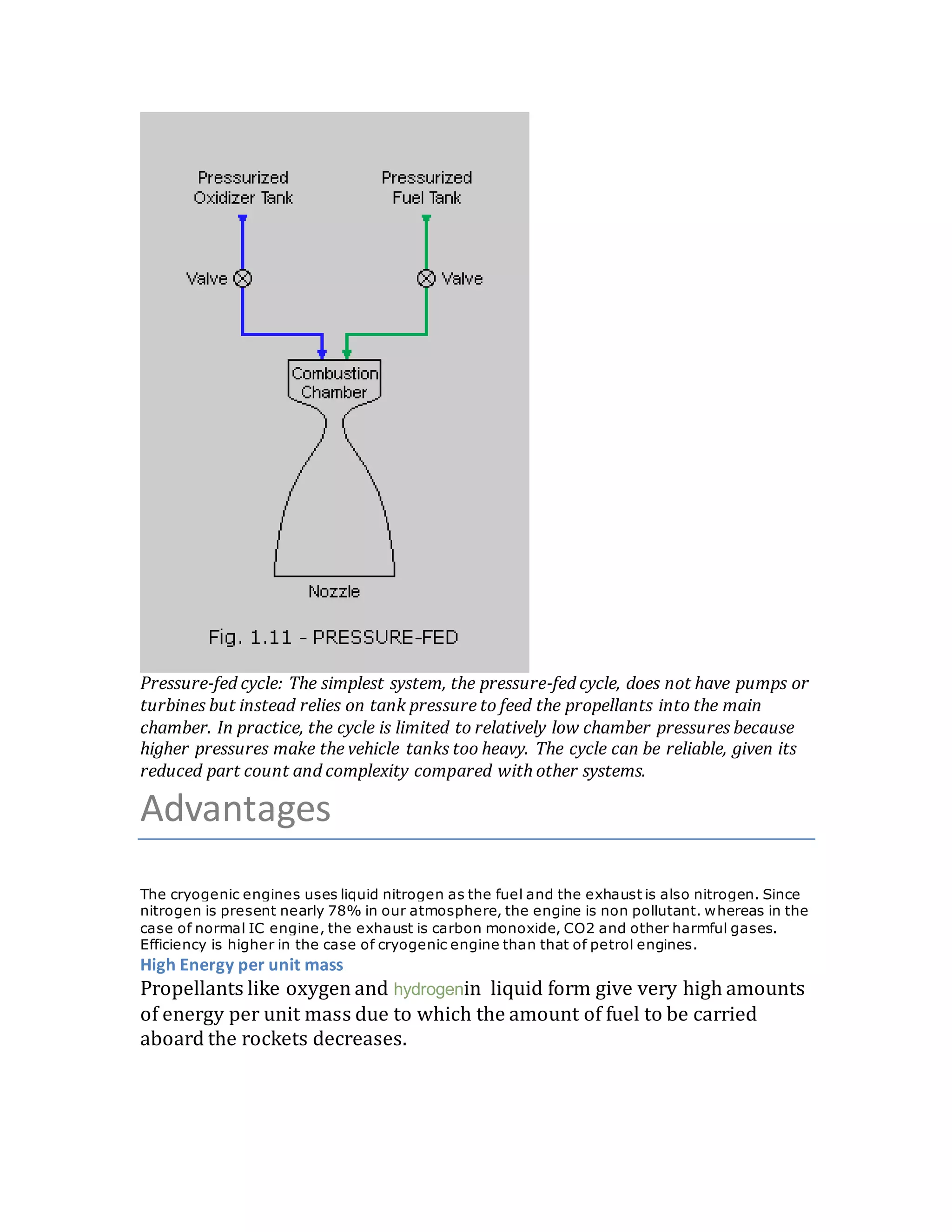
![Pressure-fed engines have practical limits on propellant pressure, which in turn limits combustion
chamber pressure. High pressure propellant tanks require thicker walls and stronger alloys which
make the vehicle tanks heavier. Thereby reducing performance and payload capacity. The lower
stages of launch vehicles often use solid fuel and pump-fed liquid fuel engines instead, where
high pressure ratio nozzles are considered desirable.[citation needed]
Expander cycle (rocket)
From Wikipedia,the free encyclopedia
(Redirected from Expander cycle)
Expander rocket cycle. Expander rocket engine (closed cycle). Heat from the nozzle and combustion chamber
pow ers the fuel and oxidizer pumps.
The expander cycle is a pow er cycle of a bipropellant rocket engine meant to improve the efficiency of fueldelivery.
In an expander cycle, the fuelis heated before it is combusted, usually w ith w aste heat fromthe main combustion
chamber. As the liquid fuelpasses through coolant passages in the w alls of the combustion chamber, it undergoes
a phase change into a gaseous state. The fuelin the gaseous state expands through a turbine using the pressure](https://image.slidesharecdn.com/cryogenic-rocket-engine-propellents-180426042953/75/Cryogenic-rocket-engine-propellents-8-2048.jpg)
![differentialfromthe supply pressure to the ambient exhaust pressure to initiate turbopump rotation. This can provide a
bootstrap starting capability as is used on the Pratt & Whitney RL10 engine. This bootstrap pow er is used to
drive turbines that drive the fueland oxidizer pumps increasing the propellant pressuresand flows to the rocket
engine thrust chamber. After leaving the turbine(s), the fuelis then injected w ith the oxidizer into the combustion chamber
and burned to produce thrust for the vehicle.
Because of the necessary phase change, the expander cycle is thrust limited by the square-cube rule. As the size of a
bell-shaped nozzle increases with increasing thrust, the nozzle surface area (fromwhich heat can be extracted to expand
the fuel) increases as the square of the radius. How ever, the volume of fuelthat must be heated increases as the cube of
the radius. Thus there exists a maximum engine size of approximately 300 kN of thrust beyond w hich there is no longer
enough nozzle area to heat enough fuelto drive the turbines and hence the fuel pumps. Higher thrust levels can be
achieved using a bypass expander cycle where a portion of the fuelbypasses the turbine and or thrust chamber cooling
passages and goes directly to the main chamber injector. Aerospike engines do not suffer fromthe same limitations
because the linear shape of the engine is not subject to the square-cube law. As the width of the engine increases, both
the volume of fuelto be heated and the available thermal energy increase linearly, allow ing arbitrarily wide engines to be
constructed. Allexpander cycle engines need to use a cryogenic fuelsuch as hydrogen, methane, or propane that easily
reach their boiling points.
Some expander cycle engine may use a gas generator of some kind to start the turbine and run the engine until the heat
input fromthe thrust chamber and nozzle skirt increases as the chamber pressure builds up.
In an open cycle, or "bleed" expander cycle, only some of the fuelis heated to drive the turbines, w hich is then vented to
atmosphere to increase turbine efficiency. While this increases poweroutput, the dumped fuelleads to a decrease in
propellant efficiency(lowerengine specific impulse). A closed cycle expander engine sends the turbine exhaust to the
combustion chamber (see image at right.)
Advantages
The expander cycle has a number of advantages over other designs:[citation needed]
Low temperature. The advantage is that after they have turned gaseous, the
fuels are usually near room temperature, and do very little or no damage to
the turbine, allowing the engine to be reusable. In contrast Gas-
generator or Staged combustion engines operate their turbines at high
temperature.
Tolerance. During the development of the RL10 engineers were worried that
insulation foam mounted on the inside of the tank might break off and
damage the engine. They tested this by putting loose foam in a fuel tank and
running it through the engine. The RL10 chewed it up without problems or
noticeable degradation in performance. Conventional gas-generators are in](https://image.slidesharecdn.com/cryogenic-rocket-engine-propellents-180426042953/75/Cryogenic-rocket-engine-propellents-9-2048.jpg)

![The gas generator cycleis a power cycle of a bipropellant rocket engine.Some of the propellant is burnedin a gas-generator andthe
resultinghot gas is usedto power the engine's pumps. The gas is then exhausted. Because somethingis "thrown away"this type of
engine is also known as open cycle.
There are several advantages to the gas generatorcycleover its counterpart, the stagedcombustion cycle. The gas generator turbine
does not needto deal with thecounterpressure of injectingthe exhaust intothe combustionchamber.This simplifies plumbingand
turbine design, andresults in a less expensiveandlighter engine.
The main disadvantage is lost efficiencydue to discardedpropellant.Gas generator cycles tendtohave lower specific impulse than
stagedcombustion cycles.[citation needed]
As in most cryogenic rocket engines, someof the fuel in a gas-generatorcycleis usedto cool the nozzle andcombustionchamber.
Current constructionmaterials cannot standextreme temperatures ofrocket combustionprocesses by themselves. Coolingpermits the
use of rocket engines forrelativelylongerperiods of time withtoday’s material technology. Without rocket combustionchamber and
nozzle cooling, the engine wouldfail catastrophically.[1]
Staged combustion cycle (rocket)](https://image.slidesharecdn.com/cryogenic-rocket-engine-propellents-180426042953/75/Cryogenic-rocket-engine-propellents-11-2048.jpg)
![Staged combustion rocket cycle. Usually, all of the fuel and a portion of the oxidizer are fed through the pre-burner
(fuel rich) to pow er the pumps. An oxygen rich circuit is possible also, but less common because of the metallurgy
required.
The staged combustioncycle, also called toppingcycle or pre-burner cycle,[1]
is a thermodynamic cycle
of bipropellant rocket engines. Some of the propellant is burned in a pre-burner and the resulting hot gas is used to pow er
the engine's turbines and pumps. The exhausted gas is then injected into the main combustion chamber, along w ith the
rest of the propellant, and combustion is completed.
The advantage of the staged combustion cycle is that all of the engine cycles' gases and heat go through the combustion
chamber, and overall efficiencyessentially suffersno pumping losses at all. Thus this combustion cycle is often called
closed cycle since the cycle is closed as all propellant products go through the chamber; as opposed to open cycle w hich
dumps the turbopump driving gases, representing a few percent of loss.
Another very significant advantage that staged combustion gives is an abundance of pow er which permits very high
chamber pressures. Veryhigh chamber pressures mean high expansion ratio nozzles can be used, w hilst stillgiving
ambient pressures at takeoff. These nozzlesgive far better efficienciesat low altitude.
The disadvantages of this cycle are harsh turbine conditions, that more exotic plumbing is required to carry the hot gases,
and that a very complicated feedbackand controldesign is necessary. In particular, running the full oxidizer stream
through both a pre-combustor and main-combustor chamber (oxidizer-rich staged combustion) producesextremely
corrosive gases. Thus most staged-combustion engines are fuel-rich, as in the schematic.
Staged combustion engines are the most difficult types of rocket engines to design. A simplified version is called the gas-
generator cycle.
Power Cycles
Liquid bipropellant rocket engines can be categorized according to their power cycles,
that is, how power is derived to feed propellants to the main combustion chamber.
Described below are some of the more common types.
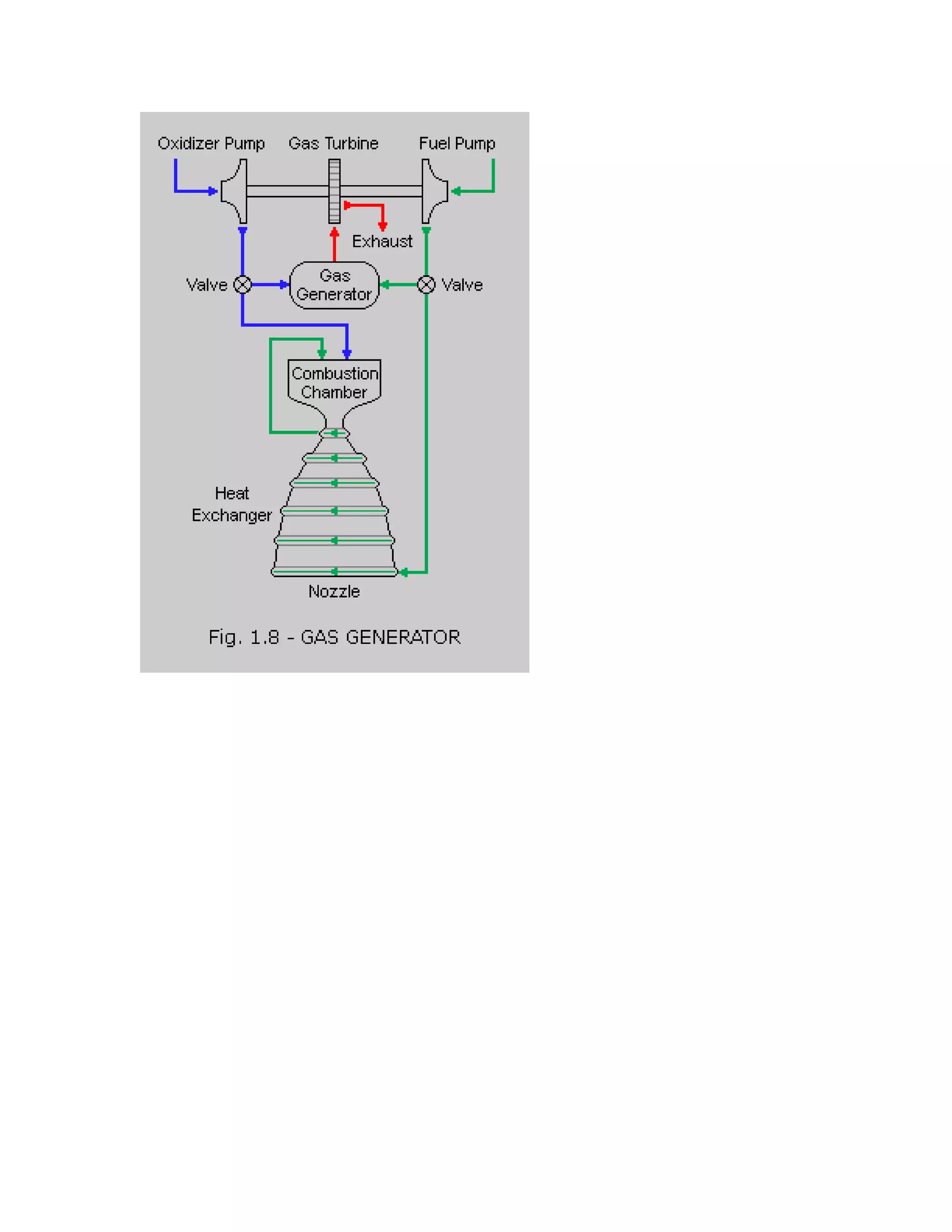
Gas-generator cycle: The gas-generator cycle, also called open cycle, taps off a small
amount of fuel and oxidizer from the main flow (typically 3 to 7 percent) to feed a
burner called a gas generator. The hot gas from this generator passes through a
turbine to generate power for the pumps that send propellants to the combustion
chamber. The hot gas is then either dumped overboard or sent into the main nozzle
downstream. Increasing the flow of propellants into the gas generator increases the
speed of the turbine, which increases the flow of propellants into the main combustion
chamber, and hence, the amount of thrust produced. The gas generator must burn
propellants at a less-than-optimal mixture ratio to keep the temperature low for the
turbine blades. Thus, the cycle is appropriate for moderate power requirements but](https://image.slidesharecdn.com/cryogenic-rocket-engine-propellents-180426042953/75/Cryogenic-rocket-engine-propellents-12-2048.jpg)