Download as PDF, PPTX


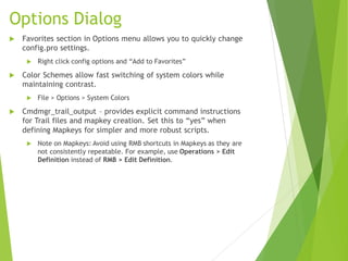

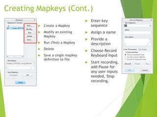
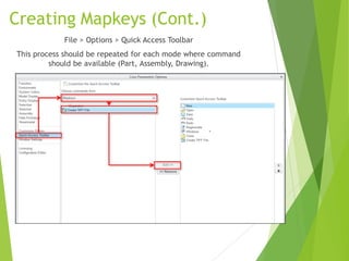

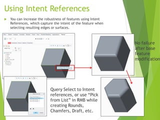


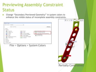


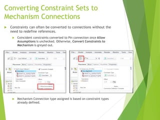

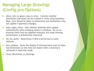
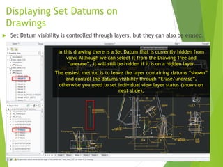
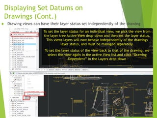
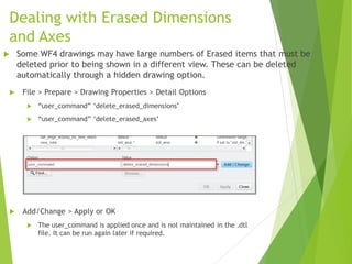


This document provides tips and tricks for using Creo Parametric 3.0. It discusses options for customizing the user interface and environment, creating mapkeys for commands, leveraging advanced part and assembly modeling techniques, managing large assemblies, using the mechanism application, and working efficiently in drawings. Specific tips covered include customizing system colors, using intent references to make features more robust, controlling assembly constraint behavior, displaying set datums, and sorting BOM tables by assembly sequence.


![Creo nocreo[1].patt.ppt](https://cdn.slidesharecdn.com/ss_thumbnails/creonocreo1-170221224001-thumbnail.jpg?width=640&height=640&fit=bounds)


![[Deck] What's New in Spark-Iceberg Integration via DSV2.pptx](https://cdn.slidesharecdn.com/ss_thumbnails/deckwhatsnewinspark-icebergintegrationviadsv2-260210005337-25955b12-thumbnail.jpg?width=640&height=640&fit=bounds)


